Volume 2006, Article ID 64645, Pages1–8 DOI 10.1155/ASP/2006/64645
Optimal Design of Noisy Transmultiplexer Systems
Huan Zhou1and Lihua Xie2
1Signal Processing Group, Institute of Physics, University of Oldenburg, 26111 Oldenburg, Germany 2School of Electrical and Electronic Engineering, Nanyang Technological University, Singapore 639798 Received 31 October 2004; Revised 26 August 2005; Accepted 19 September 2005
Recommended for Publication by Yuan-Pei Lin
An optimal design method for noisy transmultiplexer systems is presented. For a transmultiplexer system with given transmit-ters and desired crosstalk attenuation, we address the problem of minimizing the reconstruction error while ensuring that the crosstalk of each band is below a prescribed level. By employing the mixedH2/H∞optimization, we will ensure that the system with suboptimal reconstruction error is more robust and less sensitive to the changes of input signals and channel noises. Due to the overlapping of adjacent subchannels, crosstalk between adjacent channels is expected. And the problem of crosstalk attenua-tion is formulated as anH∞optimization problem, solved in terms of linear matrix inequalities (LMIs). The simulation examples demonstrate that the proposed design performs better than existing design methods.
Copyright © 2006 Hindawi Publishing Corporation. All rights reserved.
1. INTRODUCTION
Transmultiplexers (TMUX) were studied in the early 1970’s by Bellanger and Daguet [1] for telephone applications, with original intention to convert data between time division multiplexed (TDM) format and frequency-division multi-plexed (FDM) format. They have been successfully utilized for multiuser communications. A multi-input multi-output (MIMO) M-band conventional TMUX system (Figure 1) with critical sampling (i.e., all interpolation factors equal to band number, also called as minimally interpolated TMUX in [2]) is well suited for simultaneous transmission of many data signals through a single channel by using the frequency-division multiplexing (FDM) technique. In tradi-tional distortion-free (C(z) = 1 andr(n) = 0 inFigure 1) TMUX system, the transmitters (the left filter bank){Fi(z)}
traditionally cover different uniform regions of frequency. So the signalsui(n),i=0, 1,. . .,M−1, are packed intoM
ad-jacent frequency bands (passbands of the filters) and added to obtain the composite signal q(n). With the transmitters
Fi(z),i=0, 1,. . .,M−1, chosen as ideal bandpass filters, we
can regardp(n) as a frequency-division multiplexed or FDM version of the separate signals ui(n), and the receivers (the
right filter bank){Hk(z)}decompose this signal intovi(n), i=0, 1,. . .,M−1, with the decimated version ofvi(n) being
the reconstructed signalsi(k). So, the TMUX system can be
seen as a complete TDM→FDM→TDM converter which is exactly the dual system of the subband filter bank system [3].
However, in the TMUX system, if the transmittersFi(z)
are nonideal, the adjacent spectra will actually tend to over-lap. Similarly, if the receivers Hi(z) are nonideal, then the
output signal of ith band si(k) has contribution from the
desired signal input si(k) as well as input signals of other
bandssl(k),l=i. The leakage of signal from one band to
an-other is known as crosstalk [4]. Such crosstalk phenomenon is basically caused by the downsampling operations and the fact that the transmitting filtersFi(z) are not ideal, which
is also one of the main problems in TMUX systems. There have been many studies in the past. Intuitively, crosstalk can be cancelled by employing nonoverlapped transmittersFi(z),
and bandlimiting the signalssi(k) to|ω|< σiwithσi< π, so
that there is no overlap between signals of adjacent bands in the FDM format. That is, there exists a guard band between adjacent frequency bins, which ensures no crosstalk between adjacent signals, even though the filters have nonzero transi-tion band [5]. A larger guard band implies larger permissi-ble transition band (hence lower cost) for the receiversHi(z).
However, the existence of guard bands results in that the channel bandwidth is not fully utilized in the transmission process. If transmitter filtersFi(z) are ideal with very sharp
s0(k)
M v0(n) F0(z)
u0(n)
s1(k)
M v1(n) F1(z) u1(n)
sM−1(k)
MvM−1
(n)
FM−1(z)
uM−1(n) q(n)
C(z)
t(n)
r(n)
p(n)
H0(z)
H1(z)
HM−1(z)
v0(n)
v1(n)
vM−1(n)
M
M
M
s0(k)
s1(k)
sM−1(k) .
. .
. . .
Figure1: TMUX model with channel and channel noise.
example, Vetterli [6]. In this approach, crosstalk is permit-ted in TDM→FDM converter but is cancelled at the FDM→ TDM stage. That is, even if there are no guard bands (thereby permitting crosstalk), we can eliminate the crosstalk in a manner analogous to aliasing cancellation in maximally dec-imated filter banks by a careful choice of transmitters and re-ceivers. By this approach, the filtersHi(z) andFi(z) are more
economical than those in conventional designs. In fact, note that under certain condition perfect symbol recovery may be possible even with nonideal filters having overlapping re-sponses, for instance, with the so-called biorthogonal filter bank [7].
For noise-free TMUX system, a lot of conventional re-searches have been devoted to exploit the perfect reconstruc-tion property. As such, it has been studied from the point of view of periodically time-varying (PTV) filters in [8,9], with the technique of the selection of PTV filters poles and zeros. In [10], anH2 optimization approach is used to de-sign nonuniform-band TMUX systems, resulting in Near PR (NPR) TMUX systems. Moreover, since the quadrature mir-ror filter (QMF) bank and the TMUX system are dual to each other, the design of PR TMUX system can be solved by design PR QMF system, as discussed in [5].
Unfortunately, this perfect recovery is achieved under the assumption that channel effects including channel distor-tion and additive channel noises are negligible. For practi-cal distorted channels, the orthogonality between bands is destroyed at the receiver, causing in most cases unaccept-able performance degradation. A practical channel model is shown in Figure 1which consists of linear FIR filterC(z), with orderL < M (a reasonable assumption after channel equalization), and with additive noise r(n), see [11]. The composite signal p(n) is a distorted and noisy version of {s0(k),s1(k),. . .,sM−1(k)}.
For this practical noisy TMUX system, in [12], Wiener filtering approach is presented via the least-squares method to maintain the reconstruction performance, also, Chen et al. proposed a series of studies to deal with the signal re-construction problem from the H2 optimal point of view [13–15], and recently, an MMSE approach is proposed for perfect DFT-based DMT system design [11], with the major shortcoming that the statistical properties of input and noises must be known. To improve it,H∞optimization or minimax approach is developed in [16]. Moreover, in [17], a mixed
H2/H∞design is developed for TMUX system with additive noise, but with much conservatism due to adopting the same
Lyapunov matrix for characterizing both theH2andH∞ per-formances.
In this study, we focus on a critically sampled TMUX sys-tem. It is assumed that all users are independent, that is,si
is independent of sj for i = j; and each band is allowed
to have different delays di for constructing its input. Both
the transmitters and receivers are assumed to be FIR filters and channel noiser(n) is a white noise [11]. We address the problem of minimizing the reconstruction error while en-suring that the crosstalk is below certain level in the pres-ence of channel noise. We will first design optimal and robust receivers to reconstruct the input signals with the optimal reconstruction error in the noisy channel. For the crosstalk optimization problem, some H∞ constraints are added to ensure the TMUX system within desired crosstalk attenu-ation levels. Our solution is given in terms of linear ma-trix inequalities (LMIs) which can be solved easily by con-vex optimization [18]. As illustrated later, compared with the existing TMUX design method via LMI technique [17], the proposed method embodies two obvious advantages. First, when the reconstruction performance is concerned, the pro-posed mixedH2/H∞optimization method provides less con-servative results. Second, a multiobjective TMUX system is-sue has been explored in this study, in particular, the isis-sue on both optimal reconstruction performance and the crosstalk attenuation is novelly formulated and solved via LMI tech-nique.
2. H2OPTIMIZATION ON RECONSTRUCTION ERROR
In this section, we will establish the state-space model of the noisy TMUX system first, then formulate itsH2optimization by LMIs.
Remark 1. In a practical TMUX system, most TMUX sys-tems apply an FIR equalizer in order to shorten the eff ec-tive length of the physical channel impulse response, mod-eled as an FIR filterC(z) with orderL(usually, the orderL
ofC(z) is smaller than the interpolation factorM[2], which is called as the LS shortening [19]), and may be multichan-nel case Ci(z) (i = 0, 1,. . .,M −1) in some TMUX
sys-tem applications. For the convenience of further discussion, throughout the paper, we will combine each transmitting fil-ter Fi(z) with subchannel Ci(z) together, and describe the Ci(z)Fi(z) as new transmitting filterFi(z), without specific
s(k)
M P(z) M
— —
— s(k) G(z)
Figure2: The polyphase identity.
2.1. State-space description of TMUX systems
Note that even though the decimator and expander are time-varying building blocks, the cascaded system shown inFigure 2is in fact time invariant from an input and output point of view, which is the so-called property of polyphase identity [5]. That is,
SzMP(z)|↓ M=S(z)
P(z)|↓M
=S(z)G(z), (1) whereG(z) is the 0th polyphase component ofP(z) andS(z) is thez-transform of the inputs(k).
As shown inFigure 1, by the polyphase identity property, we know that the TMUX system is an M-inputM-output LTI systems. To facilitate later analysis, here we assume the maximum channel delays asd, the maximum length ofM
transmitting filters aslf andlhforMreceiving filters. Now
we analyze the system via a state-space approach.
Letvj(k),uj(k),r(k), p(k), andvj(k) (j=0, 1,. . .,M−
1) be the vector representations of the jthM-block of the signalsvj(n),uj(n),r(n), p(n), andvj(n), respectively. For
example,
vj(k)=
vj(n),vj(n+ 1),. . .,vj(n+M−1)
T ∈RM,
n=kM.
(2)
It is clear that
vj(k)=
1 0 · · · 0Tsj(k)=αsj(k), (3)
whereα=[1 0···0T]. The transmitterFjis assumed to have
the following state-space realization:
xjf(n+ 1)=Af,jxjf(n) +Bf,jvj(n),
uj(n)=Cf,jxfj(n) +Df,jvj(n).
(4)
By lifting the input and output of the filterFj(M-blocking)
and considering (3), we get
xfj(k+ 1)=Af,jxjf(k) +Bf,jsj(k),
uj(k)=Cf,jxjf(k) +Df,jsj(k),
(5)
where
Af,j=
AM
f,j
lf×lf, Bf,j=
AM−1 f,j Bf,j
lf×1,
Cf,j=
⎡ ⎢ ⎢ ⎢ ⎢ ⎣
Cf,j Cf,jAf,j
.. .
Cf,jAMf,−1j
⎤ ⎥ ⎥ ⎥ ⎥ ⎦
M×lf
, Df,j=
⎡ ⎢ ⎢ ⎢ ⎢ ⎢ ⎢ ⎢ ⎣
Df,j Cf,jBf,j Cf,jAf,jBf,j
.. .
Cf,jAMf,−2j Bf,j
⎤ ⎥ ⎥ ⎥ ⎥ ⎥ ⎥ ⎥ ⎦
M×1
.
(6)
Then block all inputssj(k) and outputs of synthesis filter
bankuj(k), that is,
s(k)=s0(k),s1(k),. . .,sM−1(k)T ∈RM,
u(k)=uT
0(k),uT1(k),. . .,uTM−1(k)
T
∈RM2 . (7)
A state-space realization of the model of the transmit-ter system from{s0(k),. . .,sM−1(k)} → {u0(k),. . .,uM−1(k)} can be obtained as
Xf(k+ 1)=AfXf(k) +Bfs(k), (8) u(k)=CfXf(k) +Dfs(k), (9)
where
Xf(k)=xf
0(k),x1f(k),. . .,xMf−1(k)
T
, Af =diagA
f,0,. . .,Af,M−1, Bf =diagB
f,0,. . .,Bf,M−1, Cf =diagC
f,0,. . .,Cf,M−1, Df =diagD
f,0,. . .,Df,M−1
(10)
withAf ∈RMlf×Mlf,Bf ∈RMlf×M,Cf ∈RM2×Mlf, and
Df ∈RM2×M
. So the channel inputq(n) is followed by
q(k)=βu(k), (11)
whereβ=[IM,IM,. . .,IM]∈RM×M 2
. Together with blocked channel noise r(k), which is assumed as a white Gaussian noise with varianceσ2
r and independent of the input signal s(k), the input of receivers isp(k)=q(k) +r(k).
Similarly, for the receivers, let the state-space realization of the receiverHj(z) be given by
xhj(n+ 1)=Ah,jxhj(n) +Bh,jp(n),
vj(n)=Ch,jxhj(n) +Dh,jp(n).
(12)
By applying the lifting technique and taking into account the fact that the output of the jth band is
sj(k)=
1 0 · · · 0vj(k)=αTvj(k), (13)
wherevj(k) is the lifted output ofvj(k), considering (13), we
have
xh
j(k+ 1)=Ah,jxkh(k) +Bh,jp(k),
sj(k)=Ch,jxkh(k) +Dh,jp(k),
(14)
where
Ah,j=AMh,j∈Rlh×lh,
Bh,j=
AM−1
h,j Bh,j,AMh,−2j Bh,j,. . .,Ah,jBh,j,Bh,j
∈Rlh×M,
Dh,j=
Dh,j 0 0 · · · 0
∈R1×M.
Denote
s(k)=s0(k) s1(k) · · · sM−1(k)
T
. (16)
Then the receiver system can be represented by the fol-lowing blocked state-space equations:
Xh(k+ 1)=AhXh(k) +Bhp(k),
s(k)=ChXh(k) +Dhp(k), (17)
where
Xh(k)=xh
0(k),xh1(k),. . .,xhM−1(k)
T
,
Ah=diagA
h,0,. . .,Ah,M−1, Bh=
BTh,0,. . .,B T h,M−1
T
,
Ch=diagC
h,0,. . .,Ch,M−1, Dh=
DTh,0,. . .,D T h,M−1
T
(18)
withAh ∈ RMlh×Mlh,Bh ∈ RMlh×M,Ch ∈ RM×Mlh, and
Dh∈RM×M2
.
Letdjbe the allowable delay in reconstructing the signal sj(k), withd=max(d0,d1,. . .,dM−1). A state-space realiza-tion of thedj-shiftδ(n−dj) is written as
xdj(k+ 1)=Adjxdj(k) +Bdjsj(k), sdj(k)=Cdjxdj(k), (19)
where
Ad=
0 Id−1 0 0
∈Rd×d, Bd=
⎡ ⎢ ⎢ ⎢ ⎢ ⎣
0 .. . 0 1
⎤ ⎥ ⎥ ⎥ ⎥
⎦∈R
d×1,
Cd j =
d−dj
0,. . ., 0, 1,
dj−1
0,. . ., 0
∈R1×d.
(20)
By combining the delay models of all theM-bands to-gether, we have
Xd(k+ 1)=AdXd(k) +Bds(k),
sd(k)=CdXd(k), (21)
whereXd(k)=[xd
0(k),xd1(k),. . .,xdM−1(k)]T, and
Ad=diagAd
0,. . .,AdM−1
∈RMd×Md, Bd=diagBd
0,. . .,BdM−1
∈RMd×M, Cd=diagCd
0,. . .,CdM−1
∈RM×Md.
(22)
Following from (8) and (21), for a TMUX systemEwith FIR transmitters and receivers, its IO relation between the TMUX inputs and reconstruction error is given by
(E) : X(k+ 1)=AX(k) +Bs(k),
e(k)=CX(k) +Ds(k), (23)
wheree(k)=s(k)−sd(k), the state vector
X(k)=XdT Xf T(k) XhT(k)T,
s(k)=sT(k) rT(k)T, (24)
and
A=
⎡ ⎢ ⎣
Ad 0 0
0 Af 0
0 BhβCf Ah
⎤ ⎥
⎦, B=
⎡ ⎢ ⎣
Bd 0 Bf 0 BhβDf Bh
⎤ ⎥
⎦,
C=−Cd DhβCf Ch, D=DhβDf Dh
(25)
withA ∈ RM(d+lf+lh)×M(d+lf+lh),B ∈ RM(d+lf+lh)×2M,C ∈
RM×M(d+lf+lh), andD∈RM×2M.
2.2. H2optimization on reconstruction error
Given the transmitter system (22) and allowable system de-lays, the receiver system in the form of (14) (forj=0, 1,. . .,
M−1) can be designed such that the error systemE in the form of (23) is stable and itsH2norm is minimized.
Formally, as is well known, theH2norm ofEis described by
E2 2=trace
BTQB, (26)
where Q is the observation grammian of the pair (A,C), which is the unique solution of the Lyapunov equation
ATQA−Q+CTC=0. (27)
Having recast the problem as above, we now use the LMI approach [20] to solve it.
Theorem 1. The optimal receiver system for the noisy TMUX system can be solved by the optimization:
min
S,Q,Ch,DhE
2
2= min
S,Q,Ch,Dhtrace(S) (28)
subject to
L1=
⎡ ⎢ ⎣
−S BTQ DT QB −Q 0
D 0 −I ⎤ ⎥ ⎦<0,
L2=
⎡ ⎢ ⎣
−Q ATQ CT QA −Q 0
C 0 −I ⎤ ⎥ ⎦<0,
(29)
whereA,B,C, andD are defined in(25), andS =ST and Q=QT.
The proof of the theorem readily follows from the way the problem is formulated and applying the Schur complements to (26) and (27).
Remark 2. It can be observed that (29) are linear inQ,S, and receiver parametersCh,j,Dh,j(forj=0, 1,. . .,M−1), which
are involved inCh andDh. Thus, the optimization in the
3. MIXEDH2/H∞OPTIMIZATION ON RECONSTRUCTION ERROR
It is well known that one of the major drawbacks ofH2 op-timization is that the statistical properties (or the models) of the input signals and channel noises must be well known be-forehand. To deal with general noisy TMUX system, we con-sider a worst-case reconstruction error, such performance can be very effectively described usingH∞related criteria.
To optimize the average (H2) reconstruction perfor-mance while ensuring a certain level of the worst-case error energy over all possible inputs and channel noises, the mixed
H2/H∞optimization is to be sought.
If the error system (23) is stable, itsH∞norm is defined as
E∞= sup s2=0
e2
s2. (30)
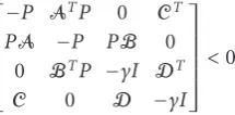
Moreover, its value is bounded by a prescribed scalarγif and only if the following inequality holds:
⎡ ⎢ ⎢ ⎢ ⎢ ⎣
−P ATP 0 CT PA −P PB 0
0 BTP −γI DT C 0 D −γI ⎤ ⎥ ⎥ ⎥ ⎥
⎦<0. (31)
Proof. Equation (31) can be easily derived by applying the Schur complements and the well-known bounded real lem-ma.
Then the mixedH2/H∞optimization can be solved as fol-lows.
Theorem 2. Give a scalarγ >0, the mixedH2andH∞
recon-struction problem is solvable if and only if theH∞
reconstruc-tion problem is solvable. In this situareconstruc-tion, the optimal mixed H2 andH∞ receivers can be obtained by the following convex
optimization:
E2
2= min
S,Q,P,Ch,Dhtrace(S) (32)
subject to LMIs(29), and(31), withS = ST,Q = QT, and P=PT.
Remark 3. Note that in [17], a mixed H2/H∞ approach is proposed for the design of IIR receivers for a noisy TMUX system. The approach of [17] is generally conservative due to the fact that the same Lyapunov matrix is adopted for both theH2andH∞performances. That is, only an upper bound on theH2performance (suboptimal mixedH2/H∞receivers) is achieved. In the above, we proposed a mixedH2/H∞ de-sign for TMUX systems via a convex optimization which al-lows different Lyapunov matricesQandPfor theH2andH∞ performances. The result ofTheorem 2is necessary and suf-ficient. That is, it will lead to the optimal solution rather than a suboptimal solution.
4. H∞OPTIMIZATION ON CROSSTALK ATTENUATION
In this section, we will deal with the crosstalk problem by an
H∞optimization approach. In general, there are two reasons for the study of crosstalk attenuation byH∞approach.
First, as stated before, one problem often encountered in a TMUX system is crosstalk, for example, the crosstalk be-tween multiple services transmitting through the same tele-phone cable is the primary limitation to digital subscriber line services [21]. Usually, special requirement on system crosstalk performance is imposed, for example, in the British telecommunication specifications, for a 60-channel TMUX, at least 60 dB interchannel crosstalk attenuation is required [8], which is a less strict requirement than crosstalk cancella-tion, means less cost for implementation.
The second is, in TMUX system, there are many fac-tors resulting in modeling uncertainty, which, in most cases, may destroy the perfect crosstalk cancellation property and cause unacceptable performance degradation [12]. So, with
H∞optimization, crosstalk can be controlled even from the worst-case point of view.
4.1. Problem formulation
As stated before, the leakage from one band to another is known as the crosstalk which is the effect of other band in-putssl(k),l=i, on theith band outputsi(k),i=0, 1,. . .,M−1.
Apply the polyphase identity to the TMUX system in Figure 2and definePi j(z)=Hi(z)C(z)Fj(z) andGi j(z) the
0th polyphase component ofPi j(z). Then, the output of the ith band is given as
Si(z)=Gii(z)Si(z) + M−1
j=0,j=i
Gi j(z)Sj(z)=Sii(z) +Sc,i(z),
(33)
whereSi(z) is thez-transform ofsi(k) andSc,i(z) is due to
the inputs of other bands and is termed as crosstalk in theith band.
In general, the crosstalk in theith band is composed of (M−1) leakages from (M−1) inputsj,j=0,. . .,i−1,i+
1,. . .,M−1. However, this can be simplified considerably if we assume that crosstalk only appears between adjacent channels [3], that is, for a TMUX system,Hi(z) andFi(z)
have the same frequency support domain andHi(z)Hj(z)≈
0 for|i−j|>1 (nonadjacent filters practically do not over-lap). This means that the expression of theith band crosstalk distortionsc,i(n) for 1 ≤ i ≤ M−2 contains two
signifi-cant terms asFipractically overlaps only withFi−1andFi+1. Fori=0 ori=M−1 it contains only one significant term asF0overlaps only withF1andFM−1withFM−2.
We will now derive a state-space representation for each crosstalk by a lifting approach, it is clear that such represen-tation is a special case of (23), by ignoring the delays and only consideringsi−1(k), andsi+1(k) being sources of theith crosstalk output.
LetFidenote the mapping (si−1,si+1)→sc,iin the system
si−1(k) M vi−1(n)
Fi−1 ui−1(n)
si+1(k)
M vi+1(n) Fi+1 ui+1 (n) yi(n)
Hi vi
(n)
M sc,i(k)
Figure3: Composition of theith crosstalk.
Denote
sc,i(k)=
si−1(k)
si+1(k)
. (34)
Following the similar derivation as above, the crosstalk of the
ith band is given by
Ec,i
: Xc,i(k+ 1)=Ac,iXc,i(k) +Bc,isc,i(k),
sc,i(k)=Cc,iXc,i(k) +Dc,isc,i(k), i=1,. . .,M−2,
(35)
where the state vectorXc,i(k)=
xif T−1(k) xif T+1(k) xhTi (k)
T
, and
Ac,i=
⎡ ⎢ ⎢ ⎣
Af,i−1 0 0 0 Af,i+1 0
Bh,iCf,i−1 Bh,iCf,i+1 Ah,i
⎤ ⎥ ⎥
⎦,
Bc,i=
⎡ ⎢ ⎢ ⎣
Bf,i−1 0 0 Bf,i+1
Bh,iDf,i−1 Bh,iDf,i+1
⎤ ⎥ ⎥ ⎦,
Cc,i=
Dh,iCf,i−1 Dh,iCf,i+1 Ch,i
,
Dc,i=Dh,i
Df,i−1 Df,i+1
(36)
with Ac,i ∈ R(2lf+lh)×(2lf+lh), Bc,i ∈ R(2lf+lh)×2, Cc,i ∈ R1×(2lf+lh), andDc,i∈R1×2.
The state-space realizations for the crosstalks in 0th and (M−1)th bands are
Ec,0
:X0(k+ 1)=Ac,0X0(k) +Bc,0s1(k),
sc,0(k)=Cc,0X0(k) +Dc,0s1(k);
Ec,M−1:XM−1(k+ 1)=Ac,M−1XM−1(k)+Bc,M−1sM−2(k),
sc,M−1(k)=Cc,M−1XM−1(k)+Dc,M−1sM−2(k), (37)
where the state vector isXl(k)=
xlf T(k) xhTl (k)
T
,l =0, orM−1 and
Ac,l=
Af,l 0 Bh,lCf,l Ah,l
∈R(lf+lh)×(lf+lh),
Bc,l=
Bf,l Bh,lDf,l
∈R(lf+lh)×1,
Cc,l=
Dh,lCf,l Ch,l
∈R1×(lf+lh), D
c,l=Dh,lDf,l∈R.
(38)
4.2. H∞crosstalk attenuation
In this subsection, we will formulate the crosstalk attenuation problem as anH∞performance problem.
Assume that each inputsi(fori=0, 1,. . .,M−1) is energy
bounded, that is,∞k=0s2
i(k)<∞. We define the following
signal-to-crosstalk ratio (SCR) to measure the crosstalk at-tenuation. For the given transmittersFi(z),i=0, 1,. . .,M−1,
and a desirable SCR ρi, design the receivers Hi(z), i = 0,
1,. . .,M−1, such that for eachi,
SCRi=10 log10
∞
k=0s2c,i(k)
∞
k=0s2c,i(k)
=10 log10sc,i 2 2
sc,i22
≥ρi, (39)
wheresc,i(k) is defined in (34) fori = 1, 2,. . .,M−2, and sc,0(k)= s1(k) andsc,M−1(k) = sM−2(k). Note that SCRi as
defined above is in fact to measure the ratio of the input energy and output energy ofEc,i. Letγi =10−ρi/10. It is easy
to know that (39) is equivalent to
Ec,i
∞≤γi, (40)
whereEc,iis defined in (35) fori=1,. . .,M−2 and in (37)
fori=0 andi=M−1.
Theorem 3. Given the transmittersFi,i = 0, 1,. . .,M−1,
there exist receiversHi(z),i=0, 1. . .,M−1, that achieve
de-sirable signal-to-crosstalk ratio (SCR)ρfor all bands if and only if the following LMIs are satisfied:
⎡ ⎢ ⎢ ⎢ ⎣
Pi PiAc,i PiBc,i 0
(∗)T P
i 0 CcT,i
(∗)T (∗)T I DT c,i
(∗)T (∗)T (∗)T 10−ρi/10I ⎤ ⎥ ⎥ ⎥
⎦>0 (41)
fori= 0, 1,. . .,M−1, simultaneously, whereAc,i,Bc,i,Cc,i, Dc,iare the state-space matrices ofEc,ias defined in(36)and
(38).
Remark 4. Note again that (41) is linear in receiver parame-ters and can be solved using convex optimization. With The-orems1and3, the problem of designing receivers that min-imize the reconstruction errors while satisfying the crosstalk attenuation constraint can be solved by the convex optimiza-tion in (28) subject to the LMI constraint of (29) and (33).
Remark 5. Note that Chen et al. in [17] discussed a mixed
Table1: Reconstruction performance comparison between different receiver design approaches.
Constraint
SNRr0(dB)
SNRc(dB)
γ 10 15 20 25 30
γ=1 By proposed method 30.7518 35.3302 39.2135 41.8637 43.2044 By method in [17] 30.7450 35.3100 39.1938 41.7722 43.0802
γ=0.1 By proposed method 30.7476 35.3177 39.1828 41.8071 43.1274 By method in [17] 30.5784 34.9161 38.3080 40.3420 41.2496
Table2: TMUX system SNRs and SCRs comparison for different receiver designs.
SNRc=10 dB SNRc=20 dB
Band0 Band1 Band2 Band0 Band1 Band2
PR approach SCR 30.8980 26.1188 23.2797 30.8980 26.1188 23.2797 SNRr 6.7252 4.7539 4.1931 11.6430 9.4181 8.8873
OptimalH2+H∞constraint SCR 31.8695 34.1238 32.0317 33.8104 35.6299 34.6269 (ρ0=ρ1=ρ2=30 dB) SNRr 7.8125 6.2832 5.8382 12.2238 10.5223 9.8985 OptimalH2+H∞constraint SCR 74.7892 45.9977 48.9783 76.1100 54.5022 48.627
(ρ0=70,ρ1=ρ2=40 dB) SNRr 6.1514 6.0711 5.5448 6.6835 10.1444 8.5923
5. EXAMPLES
5.1. Example 1
Now we address the TMUX reconstruction problem. The model presented in [17] is considered, and we design the re-ceivers by our proposed mixedH2/H∞approach. Firstly, we define the measurement metrics on channel noise (channel signal-to-noise ratio, SNRc) and reconstruction performance (reconstruction SNR on theith band, SNRri) as
SNRc=10 log10
∞
k=0p2(k)
∞
k=0r2(k) ,
SNRri =10 log10
∞
k=0s2i(k)
∞
k=0
si(k)−sdi(k)
2.
(42)
Then the results (on the first band) are listed inTable 1. From it, it is clear that our proposed approach has a slightly better reconstruction performances than the conservative method presented in [17], because of adopting different Lya-punov matrices for theH2andH∞performances. Moreover, the more constraint onH∞performance is added, the more obvious improvement will produce.
5.2. Example 2
In this example, we will examine the crosstalk attenuation performance of a TMUX system. We consider a 3-channel filter bank model in [22], where a perfect reconstruction fil-ter bank has been designed. We adopt its dual system for a 3-band PR TMUX system model.
Under the channel noise of variance σ2
r = 0.09 and σ2
r = 0.9 (in this case, corresponding to the SNRc of 20 dB
and 10 dB, resp.), we design the receivers by the optimal
H2 design (Theorem 1) with an H∞ crosstalk constraint
(Theorem 3). A comparison is made with the original perfect reconstruction (PR) TMUX system inTable 2, under diff er-ent constraints SCRs as defined in (39).
From this table, it can be seen that, firstly, the PR design is inferior to the proposed optimal design with anH∞crosstalk constraint in both the reconstruction performance and the crosstalk attenuation; secondly, our proposedH∞constraint can obtain any desired crosstalk attenuation requirement; thirdly, when a stringent crosstalk attenuation is required, the reconstruction performance could be very poor, which shows that in some noisy TMUX system design, a trade-offbetween crosstalk attenuation and reconstruction performances is to be made.
It is worth pointing out that the overall reconstruction performance is not very good for the example mainly due to the significant frequency overlapping of the three transmit-ters.
6. CONCLUSION
In this paper, we have investigated the optimal receivers de-sign for noisy transmultiplexer systems with the goal of opti-mizing the reconstruction error while ensuring the crosstalk attenuation below a given level. The former is optimized by
H2 approach, while the latter is formulated and solved by
H∞approach. The simulation results indicated that in noisy situations, the proposed design improves the system perfor-mance in both the reconstruction and crosstalk attenuation, when compared with the biorthogonal transmultiplexer de-sign approach.
REFERENCES
[2] Y.-P. Lin and S.-M. Phoong, “ISI-free FIR filterbank transceivers for frequency-selective channels,”IEEE Transac-tions on Signal Processing, vol. 49, no. 11, pp. 2648–2658, 2001. [3] M. Vetterli, “A theory of multirate filter banks,”IEEE Transac-tions on Acoustics, Speech, and Signal Processing, vol. 35, no. 3, pp. 356–372, 1987.
[4] H. Scheuermann and H. G¨ockler, “A comprehensive survey of digital transmultiplexing methods,”Proceedings of the IEEE, vol. 69, no. 11, pp. 1419–1450, 1981.
[5] P. P. Vaidyanathan, Multirate Systems and Filter Banks, Prentice-Hall, Englewood Cliffs, NJ, USA, 1993.
[6] M. Vetterli, “Perfect transmultiplexers,” inProceedings of IEEE International Conference on Acoustics, Speech, and Signal Pro-cessing (ICASSP ’86), vol. 11, pp. 2567–2570, Tokyo, Japan, April 1986.
[7] R. D. Koilpillai, T. Q. Nguyen, and P. P. Vaidyanathan, “Some results in the theory of crosstalk-free transmultiplexers,”IEEE Transactions on Signal Processing, vol. 39, no. 10, pp. 2174– 2183, 1991.
[8] J. Critchley and P. J. W. Rayner, “Design methods for period-ically time varying digital filters,”IEEE Transactions on Acous-tics, Speech, and Signal Processing, vol. 36, no. 5, pp. 661–673, 1988.
[9] J. S. Prater and C. M. Loeffler, “Analysis and design of period-ically time-varying IIR filters, with applications to transmulti-plexing,”IEEE Transactions on Signal Processing, vol. 40, no. 11, pp. 2715–2725, 1992.
[10] T. Liu and T. Chen, “H2optimization applied to general trans-multiplexer design,” inProceedings of the 39th IEEE Conference on Decision and Control, vol. 5, pp. 4314–4319, Sydney, NSW, Australia, December 2000.
[11] Y.-P. Lin and S.-M. Phoong, “Perfect discrete multitone mod-ulation with optimal transceivers,”IEEE Transactions on Signal Processing, vol. 48, no. 6, pp. 1702–1711, 2000.
[12] B.-S. Chen and L.-M. Chen, “Optimal reconstruction in mul-tirate transmultiplexer systems under channel noise: Wiener separation filtering approach,”Signal Processing, vol. 80, no. 4, pp. 637–657, 2000.
[13] B.-S. Chen, C.-W. Lin, and Y.-L. Chen, “Optimal signal recon-struction in noisy filter bank systems: multirate Kalman syn-thesis filtering approach,”IEEE Transactions on Signal Process-ing, vol. 43, no. 11, pp. 2496–2504, 1995.
[14] B.-S. Chen and C.-W. Lin, “Optimal design of deconvolution filters for stochastic multirate signal systems,”Signal Process-ing, vol. 47, no. 3, pp. 287–305, 1995.
[15] C.-W. Lin and B.-S. Chen, “State space model and noise fil-tering design in transmultiplexer systems,”Signal Processing, vol. 43, no. 1, pp. 65–78, 1995.
[16] Y.-M. Cheng, B.-S. Chen, and L.-M. Chen, “Minimax de-convolution design of multirate systems with channel noises: a unified approach,”IEEE Transactions on Signal Processing, vol. 47, no. 11, pp. 3145–3149, 1999.
[17] B.-S. Chen, C.-L. Tsai, and Y.-F. Chen, “MixedH2/H∞filtering design in multirate transmultiplexer systems: LMI approach,”
IEEE Transactions on Signal Processing, vol. 49, no. 11, pp. 2693–2701, 2001.
[18] P. Gahinet, A. Nemirovski, A. J. Laub, and M. Chilali,LMI Control Toolbox—for Use with MATLAB, The MathWorks, Natick, Mass, USA, 1995.
[19] N. Al-Dhahir and J. M. Cioffi, “Optimum finite-length equal-ization for multicarrier transceivers,” IEEE Transactions on Communications, vol. 44, no. 1, pp. 56–64, 1996.
[20] S. Boyd, L. El Ghaoui, E. Feron, and V. Balakrishnan, Lin-ear Matrix Inequalities in System and Control Theory, SIAM, Philadelphia, Pa, USA, 1994.
[21] L. C. Chu and M. Brooke, “A study on multiuser DSL chan-nel capacity with crosstalk environment,” inProceedings of the IEEE Pacific Rim Conference on Communications, Computers and signal Processing (PACRIM ’01), vol. 1, pp. 176–179, Vic-toria, BC, Canada, August 2001.
[22] C. Zhang and Y. Liao, “A sequentially operated periodic FIR filter for perfect reconstruction,”Circuits, Systems, and Signal Processing, vol. 16, no. 4, pp. 475–486, 1997.
Huan Zhou received the B.E. and M.E. degrees in information engineering from Northeastern University in 1994 and 1999, respectively, and the Ph.D. degree in elec-trical and electronic engineering from the Nanyang Technological University, Singa-pore, in 2003. She worked as a Postdoctoral Fellow in International Graduate School for Neurosensory Science and Systems, Ger-many, in 2004. Currently, she is working
with Panasonic Singapore Laboratories, focused on AV systems’ re-search and development.
Lihua Xiereceived the B.E. and M.E. de-grees in electrical engineering from Nan-jing University of Science and Technology in 1983 and 1986, respectively, and the Ph.D. degree in electrical engineering from the University of Newcastle, Australia, in 1992. He is currently a Professor with the School of Electrical and Electronic Engineering, Nanyang Technological University, Singa-pore. He held teaching appointments in the