Available online:
https://edupediapublications.org/journals/index.php/IJR/
P a g e | 522Vaddemoni Swarna Rekha
[email protected]
A b stract :Renewable energy sources are getting more and more widespread, mainly due to the fact that they generate energy by keeping the environment clean. Most of these systems have an isolation transformer included, which if excluded from the system would increase the efficiency and decrease the size of PV installations, furthermore it would lead to a lower cost for the whole investment. For safety reasons grid connected PV systems include galvanic isolation. In case of transformerless inverters, the leakage ground current through the parasitic capacitance of the PV panels, can reach very high values. A common-mode model based on analytical approach is introduced, used to predict the common-mode behavior, at frequencies lower than 50kHz, of the selected topologies and to explain the influence of system imbalance on the leakage current. It will be demonstrated that the neutral inductance has a crucial influence on the leakage current method.
Key wo rd s -Leakage current, parasitic capacitance, switching converter.
I. INTRODUCTION
The importance of renewable energy sources is recognizedby both the general public and the power industries. Someresearchers believe the concern for environmental damage isnow an even greater priority than the need to preserve thefinite natural resources for future generations.PHOTOVOLTAIC (PV) inverters become more and morewidespread within both private and commercial circles.These grid/load-connected inverters convert the availabledirect current supplied by the PV panels and feed it into theutility grid/load. There are two main topology groups used inthe case of grid/load-connected PV systems, namely, withand without galvanic isolation. Galvanic isolation can be onthe dc side in the form of
a high-frequency dc–dc transformeror on the grid/load side in the form of a big bulky actransformer. Both of these solutions offer the safety andadvantage of galvanic isolation, but the efficiency of thewhole system is decreased due to power Losses in these extracomponents.An improvement in inverter efficiency and a reduction incost have been achieved by omitting the 50 Hz powertransformer (transformer less) and by optimizing the Invertercurrent control strategies. The inverter described in thisproject is specifically for grid/Load-connected PV Systems, itcan be used for other traditional applications such as inuninterruptible Power supplies (UPS), motor controls andvoltage regulation systems. The main aim of this project wasto develop a new design procedure for a single-phase,transformer less PV inverter system suitable for grid/Loadconnection, which would lead to higher inverter efficiencies,improved output power quality and reduced cost. Detailedperformance analyses of both the unipolar and the bipolarswitched inverters will be carried out before a final choice ismade.
Techniques to remove DC offset current will beinvestigated to ensure that the DC current injected into thegrid/Load system is maintained within the legal limitsirrespective of its source. To improve the quality of inverteroutput current, a suitable efficient and cost effective ripplecurrent filter design will also be developed. The specificobjectives of the project are summarized
o High efficiency
o Constant High Frequency Common Mode Voltage
o Very Small Leakage Current o Low Total Harmonic Distortion
Available online:
https://edupediapublications.org/journals/index.php/IJR/
P a g e | 523A single-phase grid-connected inverter is usuallyused for residential or low-power applications ofpower ranges that are less than 10 kW [1]. Typesof single-phase grid connected inverters havebeen investigated [2]. A common topology ofthis inverter is full-bridge three-level. The threelevel inverter can satisfy specifications throughits very high switching, but it could alsounfortunately increase switching losses, acousticnoise, and level of interference to otherequipment. Improving its output waveformreduces its harmonic content and, hence, also thesize of the filter used and the level ofelectromagnetic interference (EMI) generated bythe inverter’s switching operation [3]. Multilevelinverters are promising; they have nearlysinusoidal output-voltage waveforms, outputcurrent with better harmonic profile, lessstressing of electronic components owing todecreased voltages, switching losses that arelower than those of conventional two-levelinverters, a smaller filter size, and lower EMI,all of which make them cheaper, lighter, andmore compact [3], [4].
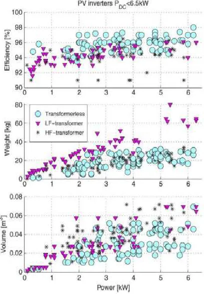
Fig. 1 has been made from the database of morethan 400 commercially available PV inverters,presented in a commercial magazine about PVsystems. The conclusion drawn from thesegraphs is that transformer less inverters havehigher efficiency and smaller weight and sizethan their counterparts with galvanic separation.
Fig.1. Advantages and drawback of differentinverter topologies.
II. PREVIOUS W ORK
In order to minimize the ground leakage currentthrough the parasitic capacitance of the PVarray, several techniques have been used.One of them is to connect the midpoint of thedc-link capacitors to the neutral of the grid, likethe half-bridge, neutral point clamped (NPC), orthree-phase full bridge with a split capacitortopology, thereby continuously clamping the PVarray to the neutral connector of the utility grid.
Available online:
https://edupediapublications.org/journals/index.php/IJR/
P a g e | 524capacitivedivider to which the neutral terminal of the gridis connected. An extra control loop is introducedthat compensates for any dc current injection, bycontrolling the voltage of both capacitivedividers to be equal.
Another solution is to disconnect the PV arrayfrom the grid, in the case of H-bridge (HB)inverters, when the zero vector is applied to theload (grid). This disconnection can be doneeither on the dc side of the inverter (like thetopology from and H5 topology from SolarTechnologies AG) or on the ac side (like theHighly Efficient and Reliable Inverter Concept(HERIC) topology from Sun ways).A new topology called HB zero-voltage staterectifier (HB-ZVR) is given where the midpointof the dc link is clamped to the inverter onlyduring the zero-state period by means of a dioderectifier and one switch.
The aim of the work presented in this paper is tointroduce a common-mode model based onanalytical approach for the single phasephaseinverter connected to the utility grid with thehelp of NPC multi level inverter. This modelwill be used to predict the common-modebehavior, at frequencies lower than 50kHz, ofthe selected topologies and to explain theinfluence of system imbalance on the groundleakage current. It will also be shown, that theneutral inductance has a crucial influence on thecommon mode behavior of the topology, therebydirectly influencing the ground leakage currentof the system. Simulation results will bepresented in case of the NPC topology in orderto validate the simulation model.
III. TRA NSFORM ER LESS TOPOLOGYA NA LYSIS
As mentioned in previous works, the common mode voltage generated by a topology and modulation strategy will greatly influence the ground leakage current that flows through the parasitic capacitance of the PV array. Generally, the utility grid doesn't influence the common mode behavior of the system, thus it may be complete that the generated common mode voltage of an explicit electrical converter
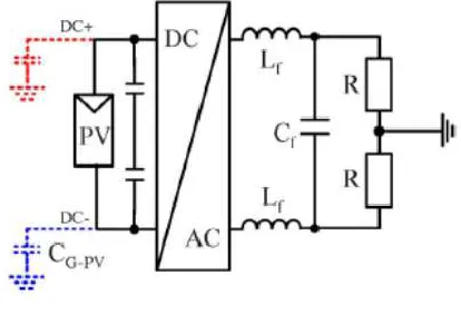
topology and modulation strategy may be shown employing a straightforward resistor as load. Therefore, within the case of simulations, solely a resistive load is employed, and therefore the common-mode voltage is measured between the dc+ terminal of the dc supply and therefore the grounded middle point of the resistor as shown in Fig. 2..
Fig. 2. Test setup used for common-mode voltage
measurement.
In the following, simulation results
obtainedusing MATLAB/SIMULINK are shown. Thesimulation step size is 0.1 μs, with an 8-kHzswitching frequency.
Simulation parameters: Lf = 1.8 mH filter inductance;
Cf = 2 μF filter capacitance;
R = 7.5 Ω load resistance;
Vdc = 350 V input dc voltage;
Cdc = 250 μF dc-link capacitance;
CG−PV = 100 nF parasitic capacitance of PVarray;
Fsw = 8 kHz switching frequency for all casesexcept that the switching frequency for unipolarPulse width modulation (PWM) has been chosento be Fsw = 4 kHz, so the output voltage
of theinverter has the same frequency for all cases.
Available online:
https://edupediapublications.org/journals/index.php/IJR/
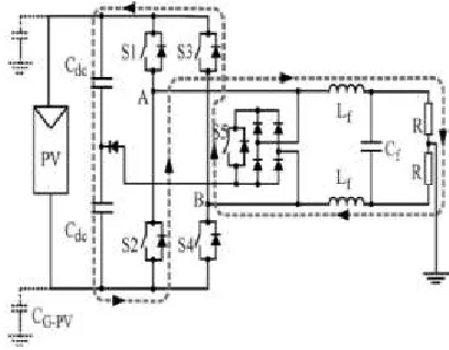
P a g e | 525Another solution for generating the zero-voltagestate can be done using a bidirectional switchmade of one IGBT and one Diode Bridge. Thetopology is detailed in Fig. 3, showing thebidirectional switch as an uxiliary componentwith a gray background. This bidirectionalswitch is clamped to the midpoint of the dc-linkcapacitors in order to fix the potential of the PVarray also during the zero-voltage vector when S1–S4 and S2–S3 are open. An extra diode isused to protect from short-circuiting the lowerdc-link capacitor.
During the positive half-wave, S1 and S4 areused to generate the active state, supplying apositive voltage to the load, as shown in Fig. 3.The zero-voltage state is achieved by turning onS5 when S1 and S4 are turned off, as shown inFig. 4. The gate signal for S5 will be thecomplementary gate signal of S1 and S4, with asmall dead time to avoid short-circuiting the input capacitor. By using S5, it is possible forthe grid current to flow in both directions; thisway, the inverter can also feed reactive power tothe grid, if necessary.
Fig. 3. Active vector applied to load, using S1 and S4 during positive half-wave.
Fig. 4. Zero vectors applied to load, using S5 during positive half-wave.
During the negative half-wave of the loadvoltage, S2 and S3 are used to generate theactive vector and S5 is controlled using thecomplementary signal of S2 and S3 andgenerates the zero voltage state, by shortcircuiting the outputs of the inverter andclamping them to the midpoint of the dc-link.
Fig. 5. Dead time between turnoff of S1 and S4 and turn on of S5 during positive half-wave.
Available online:
https://edupediapublications.org/journals/index.php/IJR/
P a g e | 526topology, where thefreewheeling current finds its path through thebidirectional switch, either through S5 or S6,depending on the sign of the current.
IV. SIM ULA TION RESULTS
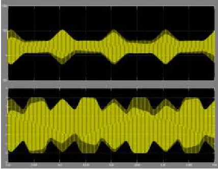
Fig. 6. HB-Unip topology: Load current and inverter output voltage.
Fig. 7. HB-Unip topology: Voltage to ground and ground leakage current.
Fig. 8. HERIC topology: Load current and inverter output voltage.
Available online:
https://edupediapublications.org/journals/index.php/IJR/
P a g e | 527Fig. 10. HB-ZVR load current and inverter output voltage.
Fig. 11. HB-ZVR topology: Voltage to ground and ground leakage current.
V. CONCLUSION
Bipolar PWM generates a constant common-mode voltage, but the efficiency of the converter is low, due to the two level output voltage. By using unipolar PWM modulation, the output of the converter will have three levels, but in this case, the generated common-mode voltage will have high-frequency components, which will lead to very high ground leakage currents.This paper has introduced a transformer less topology and given an alternative solution for the bidirectional switch, used to generate the zero-voltage state. The constant common-mode voltage of the HB-ZVR topology and its high efficiency make it an attractive solution for transformer less PV applications.
REFERENCES
[1] “Trends in photovoltaic applications: Survey report of selected IEA countries between 1992 and 2007,” IEA, Paris, France, Rep. IEA-PVPS T1-T17, 2008.
[2] J. M. Carrasco, L. G. Franquelo, J. T. Bialasiewicz, E. Galvan, R. C. P. Guisado, M. A. M. Prats, J. I. Leon, and N. Moreno-Alfonso, “Power-electronic systems for the grid integration of renewable energy sources: A survey,” IEEE Trans. Ind. Electron., vol. 53, no. 4, pp. 1002– 1016, Jul. 2008.
[3] “Photon international,” The Photovoltaic Magazine, Apr. 2007.
[4] R. Gonzalez, J. Lopez, P. Sanchis, and L. Marroyo, “Transformer less inverter for single phase photovoltaic systems,” IEEE Trans. Power Electron., vol. 22, no. 2, pp. 693–697, Mar. 2007.
Available online:
https://edupediapublications.org/journals/index.php/IJR/
P a g e | 528source inverter,” IEEE Trans. Ind. Electron., vol. 55, no. 7, pp. 2602–2609, Jul. 2008.
[6] R. Gonzalez, E. Gubia, J. Lopez, and L. Marroyo, “Transformer less single-phase multilevel-based photovoltaic inverter,” IEEE Trans. Ind. Electron., vol. 55, no. 7, pp. 2694–2702, Jul. 2008.
[7] J. Selvaraj and N. A. Rahim, “Multilevel inverter for grid-connected PV system employing digital PI controller,” IEEE Trans. Ind. Electron., vol. 56, no. 1, pp. 149–158, Jan. 2009.
[8] E. Gubía, P. Sanchis, A. Ursúa, J. Lopez, and L. Marroyo, “Ground currents in single-phase transformer less photovoltaic systems,” Prog. Photo volt., Res. Appl., vol. 15, no. 7, pp. 629–650, 2007.
[9] T. Kerekes, R. Teodorescu, and U. Borup, “Transformer less photovoltaic inverters connected to the grid,” in Proc. APEC, Feb. 25–Mar. 1, 2007, pp. 1733–1737.
[10] T. Kerekes, R. Teodorescu, C. Klumpner, M. Sumner, D. Floricau, and R. Rodriguez, “Evaluation of three-phase transformer less photovoltaic inverter topologies,” in Proc. Eur. Conf. Power Electron. Appl., Sep. 2–5, 2007, pp. 1–10.6.
A u th o r Pro file: