91
Histogram Modification Based Reversible Data Hiding
Using Neighbouring Pixel Differences
Ankita Meenpal*, Shital S Mali.
Department of Elex. & Telecomm. RAIT, Nerul, Navi Mumbai, Mumbai, University, India – 400706
Abstract- In this paper, we propose a reversible data hiding algorithm for grayscale images. Specifically, our
algorithm is based on the histogram modification technique. In this a histogram is constructed from the differences between each pixel and its neighbours. In the process of data embedding, a modified histogram shifting scheme is used to embed a secret message into the pixels whose pixel difference is located at the peak value within the histogram. Experimental results show that our algorithm can achieve higher embedding capacity and imperceptible distortion. Performance comparisons with other existing algorithms are also provided to demonstrate the feasibility of our proposed algorithm in reversible data hiding.
Index Terms- : Information hiding, Histogram processing, Reversible data hiding, Histogram modification,
Lossless data hiding, Neighbouring pixel differences.
1. INTRODUCTION
Data hiding [1] (also called information hiding) plays an important role in multimedia security. The main purpose is to conceal messages in the original medium to protect intellectual property rights, to share secret message, or for content authentication. Nevertheless, the original medium will be permanently altered and cannot be completely reconstructed after the secret message is extracted if the recovering information is not provided. In some applications, such as medical imaging, remote sensing, and military imaging, a slight distortion is not allowed. Therefore, reversible data hiding techniques have become an important research topic in recent years.
Most reversible data hiding algorithms [2–12] use images as the input media because of their easy accessibility. Images can be obtained from scanners, digital cameras, or directly downloaded from the Internet. Depending on the embedding manner of the secret message, current reversible data hiding algorithms can be classified into three domains: spatial, frequency, and compression domains. Algorithms in the spatial domain embed a secret message by directly altering the pixel value. However, algorithms in the frequency domain first transform the input image into frequency coefficients. The secret message is then embedded by coefficients modifications. Algorithms in the compression domain adopt the images represented by a series of compressed code as their embedding media. The data embedding is accomplished by modifying the compressed code.
The histogram modification scheme proposed by Ni et al. [2] is a famous reversible data hiding technique in the spatial domain. The main concept of histogram
modification is to utilize the peak and the minimum (or zero) values within the histogram of an image to embed the secret message. This scheme can be certified easily by guaranteeing that the Peak Signal-to-Noise Ratio (PSNR) value between the original image and the marked image be above 48.13 dB. However, limited data capacity is the leading problem stemming from this method. As a result, many variations of traditional histogram modification schemes are now being proposed, including prediction errors [10] and adjacent pixel difference [11,12]. The main goal of each method is still to increase the number of the peak value within the histogram of the input images.
In this paper, we propose a novel histogram modification scheme for lossless data hiding. Specifically, we calculate the differences between each processing pixel and its neighbours and then use these differences to construct the histogram, while the secret message is also embedded into the pixels located at the peak value based on a histogram shifting scheme. Experimental results and performance comparison demonstrate that our technique is feasible for reversible data hiding in grayscale images.
2. RELATED WORK
In this section, we will introduce Ni et al.’s histogram modification algorithm. Up-to-date histogram-based algorithms are also provided, including the use of prediction errors and adjacent pixel difference.
92 Ni et al. proposed a reversible data hiding algorithm
for grayscale images based on a histogram modification algorithm. For a given grayscale image, they first count the frequency of each pixel value and then generate a histogram. Thereafter two values, called the peak and the minimum, are obtained according to the frequency of each value. The peak value PV has the maximum frequency; while the minimum value MV has the minimum frequency. The minimum value MV can be called the zero value ZV if its frequency is equal to zero. If the frequency of MV is not equal to zero, all positions of the pixels with the value MV must be recorded previously. Without loss of generality, we assume PV is smaller than MV. In the next step, all pixels with value between PV + 1 and MV − 1 are modified by shifting by a value of one toward MV. In other words, one is added into the above pixels. Now, the frequency of the value PV + 1 will be equal to zero and this value will be used for data embedding later. In the data embedding process, each pixel in the original image is scanned sequentially in the raster scan order. If one pixel has a value equal to PV, its value will be modified according to the secret message SM (see (1)), where and are the values of the pixel located at the i th row and the j th column in the original and the marked images respectively. If SM is equal to 0, the marked pixel value is equal to the original value; while SM is equal to 1, the marked pixel value will be equal to PV+1. Thus, a marked image with a secret message embedded is obtained after the embedding process. In the extracting process, each pixel is still visited using the same scanning order as the embedding order. If a pixel has the value PV + 1, one-bit secret message 1 is extracted; while one-bit secret message 0 is extracted if a pixel has the value PV. The original pixel value can be recovered as the value PV for the above pixels (see (2)). However, for the pixels with a value between PV + 2 and MV, we can recover them by subtracting one. Finally, the original image can be derived after resetting the value of the pre-recorded position as MV if the frequency of MV is not equal to 0. From the above illustration, the embedding capacity for the above method is determined by the number of the pixels with the value PV. Of course, one can choose more than one pair of PV and MV to increase the size or number of the secret message. However, the low embedding capacity is still the main disadvantage; despite the fact that produced marked images have relatively high image quality with a PSNR value more than 48.13 dB.
Li et al. [11] proposed a novel data hiding method based on adjacent pixel difference (APD) to increase the frequency of PV. Their proposed technique maintains high image quality for histogram based algorithms. The authors observed that a natural image usually contains several smooth areas and thus there should be little difference between two adjacent pixels. Consequently the APD algorithm first used the inverse-s scan to determine the visiting order for each pixel and then the difference between two continuous pixels was calculated and used to construct the histogram. Thus, the frequency of PV can be raised efficiently. However, the results of this algorithm depend on the gradient of the input image. The horizontal visiting order for each pixel may be suitable for some images; while the vertical visiting order may be excellent for other images. Of course, some images may be too complex and have indeterminate best visiting orders.
For increasing the hiding capacity, Zhao et al. [12] exploited a multilevel histogram modification (MHM) algorithm based on the pixel difference. Their proposed algorithm employs an embedding level EL to indicate the embedding bin. Thus, the information of peak and zero points is unnecessary in their proposed algorithm. First, the inverse-s order is adopted to scan the image pixels for pixel difference generation. The pixel difference larger than EL is shifted rightward EL + 1 levels, whereas the pixel difference smaller than −EL is shifted leftward EL levels. The pixel difference in the range of [−EL, EL] is then modified to the corresponding value level by level based on the multilevel embedding strategy and the secret message. However, the pixel values without secret message embedded are modified at least EL levels and cause serious distortion in the final marked images.
3. THE PROPOSED METHOD
93
Fig. 2. The illustration for pixel difference calculation
for each visiting pixel.
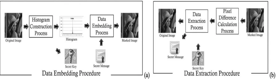
3.1 The data embedding procedure
This section illustrates the data embedding procedure in detail. This procedure starts by constructing the histogram for the input image. Thereafter, the data embedding process takes the secret message SM as input and then embeds it into the pixels located at the peak value in the constructed histogram.
3.1.1 Histogram construction process
The histogram construction of our proposed algorithm is based on the difference between each visited pixel and its neighbours. Except for the first row and the
first column, each pixel in the input image is visited in the raster order (i.e., from left to right and top to bottom). Now, we can start to calculate the pixel difference for each visiting pixel For each visiting pixel , we calculate the pixel difference with its left and upper neighbouring pixels and respectively. The equation for calculating two pixel differences is shown in (3), where C , C , and C are the pixel values of the visiting pixel and its two neighbours. and are the calculated neighbouring pixel differences. Fig. 3 illustrates the spatial representation for the above three pixels.
(3)
After two pixel differences for each pixel are calculated, we start to construct the histogram. In our proposed algorithm, the pixel can be embedded into 1.5 bit while its two pixel differences are both equal to first peak value.
One thing to be noted is that the pixels will be ignored for the histogram construction if their two pixels differences and have different signs, such as the case in Figs. 3(a) and 3(b). Such pixels may lead to extraction errors in the data extracting process. During the data embedding process, other than no modification, S will be produced to either increase Fig. 1. The flow chart of proposed algorithm, including (a) the data embedding procedure and (b) the data extraction
[image:3.595.60.542.93.232.2]procedure.
[image:3.595.86.512.624.741.2]94 or decrease at least one from C in the
histogram-based algorithms. Both pixel differences, and , are also either increased or decreased by one from the original difference after data embedding. Such modification makes one of two pixel differences approach the peak value and may lead to errors in message extraction. For example in Fig. 3(c), two pixel differences for the pixel with the value 122 are equal to 2 and −1. If the peak value is located at the value 0, this pixel cannot be used for data embedding and should shift away from the peak value. Thus, we may subtract or add one from the original pixel value and the pixel difference should be modified (see Figs. 3(d) and 3(e)). However, this action will cause this pixel to be regarded as a pixel with a secret message embedded. In order to avoid the above situation, we ignore such pixels during the histogram construction process and use the abbreviation SNP to represent the above set of pixels.
3.1.2 Data embedding process
In the embedding process, similar to previous algorithms, we also embed the secret message into the pixels whose pixel difference is located at the peak value in the histogram. All possibilities of the pixel difference for each pixel are shown in Fig. 4, where PV is the value of the peak value in the histogram. In our proposed algorithm, only the pixels in situations represented in Figs. 4(a) to 4(c) can be used for data embedding because at least one of their two pixel differences is equal to PV. The same reason as above in Fig. 3, the situations in Figs. 4(f) and 4(g) are also ignored in the data embedding process in order to avoid extraction errors.
Due to the characteristic of our proposed algorithm, there are two different shifting directions for the peak value according to different situations. For example, for the situation in Fig. 4(a), no modification occurs if SM is equal to 0; otherwise we ‘add’ one to the pixel value when SM is equal to 1. Therefore, the data embedded pixel difference for this pixel in the data extraction process should be equal to PV or PV + 1 because the other pixel difference must be larger than PV or PV + 1. On the contrary, for the situation in Fig. 4(b), if SM is equal to 0, we still take no action on the pixel; otherwise we ‘subtract’ one from the pixel value when SM is equal to 1. The data-embedded pixel difference for this pixel in the data extraction process should be equal to PV or PV−1 because the other pixel difference must be smaller than PV or PV
− 1.
Consequently, for the situation in Fig. 4(c), the pixel can have three different statuses used for data embedding, including no modification, add one or subtract one from the original pixel value. After modification, both pixel differences become PV, PV + 1, and PV − 1. These modifications do not result in an extraction error. When both the pixel differences are
equal to PV, PV+1, or PV−1 in the data extraction process, it is clear that this pixel must have the original pixel difference with the value PV. Therefore, users can integrate previous algorithms to increase the capacity efficiently for such pixels.
Finally, for the situation shown in Figs. 4(d) and 4(e), similar to previous algorithms, such pixels should shift by a value of one toward the appropriate direction in order not to be confused with the pixels having the SM embedded. Therefore, the pixel value of in Fig. 4(d) should add one to make the pixel difference larger; while the pixel value of in Fig. 4(e) should subtract one from the original pixel value to make the pixel difference smaller.
3.1.3 The data extraction procedure
The first step for data extraction is to recalculate the pixel difference between each pixel and its neighbours. The same method used in the data embedding process is performed. Because the calculation of the pixel difference is based on the original pixel values of neighbouring pixels, we must recover each pixel value right away after deriving the secret message. Thus, the post-processed pixels can derive the original pixel values of the neighbouring pixels to calculate its pixel difference. Now, we can use the raster scan order to visit each pixel, extract the secret message and then recover the original image. Note that as in the embedding process, the pixel is ignored during data extraction if two pixel differences are with different signs.
For each visiting pixel, we recalculate its two pixel differences. Thereafter, we can extract the secret message based on the pixel difference. When one of its two pixel differences is equal to the value PV, PV + 1, or PV − 1, this pixel must have the secret message embedded.
The only thing we must do is to recover the original pixel value. If both pixel differences are larger than PV + 1, the original pixel value can be recovered by subtracting one from the marked pixel value; while the pixel value can be recovered by adding one to the marked pixel value when both pixel differences are smaller than PV−1.
4. EXPERIMENTAL RESULTS
95 to represent the difference between the original image
C and the marked image S with the size M ×N. and are the pixels located at the ith row and the jth column in the original and marked respectively (see (12)). The experimental results show there is no error in the extracted secret message and the original image can be recovered from the marked image completely.
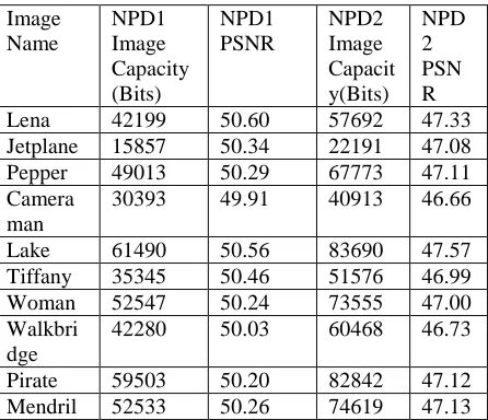
Table 1 shows the results of the embedding capacity and the visual distortion for ten input images. NPD1 indicates one peak value is used in our proposed algorithm; while NPD2 uses two peak values. The first peak value of each histogram constructed from the neighbouring pixel differences for each input image is located at the value 0; while the second peak value is not the same but is limited to values of 1 or −1. Note that only the first peak value can have two different shifting directions where the second peak is only shifted away from the first peak value.
Table 1. The results of the embedding capacity and the visual distortion for ten input images.
Image Name
NPD1 Image Capacity (Bits)
NPD1 PSNR
NPD2 Image Capacit y(Bits)
NPD 2 PSN R Lena 42199 50.60 57692 47.33 Jetplane 15857 50.34 22191 47.08 Pepper 49013 50.29 67773 47.11 Camera
man
30393 49.91 40913 46.66
Lake 61490 50.56 83690 47.57 Tiffany 35345 50.46 51576 46.99 Woman 52547 50.24 73555 47.00 Walkbri
dge
42280 50.03 60468 46.73
Pirate 59503 50.20 82842 47.12 Mendril 52533 50.26 74619 47.13
From Table 1, it is obvious that the data capacity for NPD1 can achieve 44 168 bits on average with the PSNR value around 50 dB. For NPD2, the data capacity can achieve 61 885 bits on average with the PSNR value around 47 dB. As mentioned above, the lower bound of PSNR values for histogram-based algorithms should be 48.13 dB because the maximum MSE between the original image and the marked image is equal to 1. For NPD1, each pixel has the largest shift with the value 1. Therefore, the PSNR value of each test image under the situation NPD1 is
over 48.13 dB. For NPD2, when the pixel difference of a pixel is equal to the second peak value, the maximum distortion for such a pixel may be equal to 2, as compared to the original pixel value. This is because the pixel has been shifted once when embedding the secret message into the first peak value. Therefore, the lower bound of the PSNR for NPD2 value will be 42.11 dB. However, from the experimental results in Table 1, the PSNR value for NPD1 and NPD2 in each test image is much higher than the lower bound. One reason for this phenomenon is that a secret message can have a value 0 such that the pixel value is not necessarily modified. The other reason is that the value of the pixels in the set SNP is also never modified.
5. CONCLUSION AND FUTURE WORK
In this paper, a reversible data hiding algorithm based on neighbouring pixel difference is presented. Compared to traditional histogram modification techniques, our technique constructs the histogram based on the neighbouring pixel difference instead of using the pixel value directly. The proposed method can achieve higher data capacity and better image quality for marked images than the existing up-to-date algorithms [10–12]. Experimental results demonstrate that our technique is feasible for reversible data hiding using images. However, there are still some further improvements that can be made to our proposed technique. With respect to the embedding capacity, the pixels in the cover about 30 percent of the total number of pixels for each test image. Although these pixels do not influence the decrease of the PSNR value because there is no modification, we could do additional processing on these pixels, such as integrating the prediction method. Extending our technique to colour images rather than just employing our method three times for three individual RGB colour channels is also an interesting problem that deserves investigation.
REFERENCES
[1].F.A.P. Petitcolas, R.J. Anderson, M.G. Kuhn, Information hiding—A survey, Proc.IEEE 87 (1999) 1062–1078.
[2]. Z. Ni, Y.Q. Shi, N. Ansari, W. Su, Reversible data hiding, IEEE Trans. Circuits Syst. Video Technol. 16 (2006) 354– 362.
[3]. M.U. Celik, G. Sharma, A.M. Tekalp, E. Saber, Lossless generalized-LSB data embedding,IEEE Trans. Image Process. 14 (2005) 253–266. [4]. M.U. Celik, G. Sharma, A.M. Tekalp, Lossless
[image:5.595.69.292.431.623.2]96 [5]. D. Coltuc, J.M. Chassery, Very fast
watermarking by reversible contrast mapping, IEEE Signal Process. Lett. 15 (2001) 255–258. [6]. J. Fridrich, M. Goljan, R. Du, Invertible
authentication, in: Proceedings of SPIE, Security and Watermarking of Multimedia Contents, 2001, pp. 197–208.
[7].J. Fridrich, M. Goljan, R. Du, Lossless data embedding—New paradigm in digital watermarking, EURASIP J. Appl. Signal Process. 2 (2002) 185–196.
[8].S. Lee, C.D. Yoo, T. Kalker, Reversible image watermarking based on integer-tointeger wavelet transform, IEEE Trans. Inf. Forensics Secur. 2 (2007) 321–330.
[9].J. Tian, Reversible data embedding using a difference expansion, IEEE Trans. Circuits Syst. Video Technol. 13 (2003) 890–896.
[10].W. Hong, T.S. Chen, C.W. Chiu, Reversible data hiding for high quality images using modification of prediction errors, J. Syst. Softw. 82 (2009) 1833–1842.
[11].Y.C. Li, C.M. Yeh, C.C. Chang, Data hiding based on the similarity between neighboring pixels with reversibility, Digit. Signal Process. 20 (2010) 1116– 1128.
[12].Z. Zhao, H. Luo, Z.M. Lu, J.S. Pan, Reversible data hiding based on multilevel histogram modification and sequential recovery, Int. J. Electron. Commun. 65 (2011) 814–826.