HIGH SPEED FINITE IMPULSE RESPONSE FILTER FOR LOW
POWER DEVICES
Birinderjit Singh Kalyan1
I.INTRODUCTION
A filter is used to remove some component or modify some characteristic of a signal, but often the two terms are used interchangeably. A filter is a device or process that removes some unwanted component or feature from a signal [1]. Filtering is a class of signal processing, the defining feature of filter being the complete or partial suppression of some aspect of the signal. In signal processing, the function of a filter is to remove unwanted parts of the signal, such as random noise, or to extract useful parts of the signal, such as the components lying within a certain frequency range [2].
Fig. 1. Block diagram of basic filter Fig. 2.
A filter is an electrical network that alters the amplitude and/or phase characteristics of a signal with respect to frequency. Ideally, a filter will not add new frequencies to the input signal, nor will it change the component frequencies of that signal, but it will change the relative amplitudes of the various frequency components and/or their phase relationships. Filters are often used in electronic systems to emphasize signals in certain frequency ranges and reject signals in other frequency ranges. There are two main kinds of filter, analog and digital.
a) Analog filters b) Digital filters
A. ANALOG FILTER
An analog filter has an analog signal at both its input x(t) and its output y(t). Both x(t) and y(t) are functions of a continuous variable time (t) and can have an infinite number of values. An analog filter uses analog electronic circuits made up from components such as resistors, capacitors and op amps to produce the required filtering effect. Such filter circuits are widely used in applications such as noise reduction, video signal enhancement, graphic equalizers in hi-fi systems, and many other areas. At all stages, the signal being filtered is an electrical voltage or current which is the direct analogue of the physical quantity (e.g. a sound or video signal or transducer output) involved.
B. DIGITAL FILTER
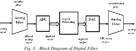
In the electronic industry, there is a device known as Digital filters which are capable of taking digital input, process them and provide digital output[4]. A digital filter uses a digital processor to perform numerical calculations on sampled values of the signal. The processor may be a general purpose computer such as a PC, or a specialized DSP (digital signal processor) chip. Digital filters [5] are used in a wide variety of signal processing applications, such as spectrum analysis, digital image processing, and pattern recognition. Digital filters eliminate a number of problems associated with their classical analog counterparts and thus are preferably used in place of analog filters. The analog input signal must first be sampled and digitized using an ADC (analog to digital converter). The resulting binary numbers, representing successive sampled values of the input signal, are transferred to the processor, which carries out numerical calculations on them. Fast
1
Electrical and Electronic Engineering Department, Chandigarh University
Abstract-The advancement in the field of CMOS technology has motivated the research to implement more and more complicated signal processing systems on a VLSI chip. The basic requirements of these signal processing units are to consume less power and have more functionality. The chip area, speed and power consumption are considered to be the criteria for evaluating the quality of the system. The increase in functionality, operating frequency and long battery life has made the low power portable electronic devices pragmatic in the recent years. The reduction in power consumption of a system, increases its battery life. In most of the signal processing algorithms, multiplication operation dominates other operations. The low power high performance multiplier plays a vital role in high performance Digital Signal Processing (DSP) systems developed using Multiply and Accumulator (MAC) unit and Finite Impulse Response (FIR) filter. Hence the designing of a low power multiplier becomes an important part in low power VLSI system design. In the recent years, the consideration of multiplier design has been focused to enhance its speed and throughput rate which are expected to affect the performance of the digital signal processing systems.
Keywords—component; formatting; style; styling; insert
DSP processors can handle complex combinations of filters in parallel or cascade (series), making the hardware requirements relatively simple and compact in comparison with the equivalent analog circuitry.
C. BASICS OF DIGITAL FILTER
A digital filter is simply a discrete-time, discrete-amplitude convolved. Basic Fourier transform theory states that the linear convolution of two sequences in the time domain is the same as multiplication of two corresponding spectral sequences in the frequency domain. Filtering is in essence the multiplication of the signal spectrum by the frequency domain impulse response of the filter [6]. A digital filter is a system that performs mathematical operations on a sampled, discrete-time signal to reduce or enhance certain aspects of that signal. This is in contrast to the other major type of electronic filter, the analog filter, which is an electronics circuit operating on continuous time analog signals. An analog signal may be processed by digital filter by first being digitized and represented as a sequence of numbers, then manipulated mathematically, and then reconstructed as a new analog signal. In an analog filter, the input signal is directly manipulated by the circuit [7]. Digital filters are very important part of DSP. In fact, their extraordinary performance is one of the key reasons that DSP has become so popular. The filters have two uses: signal separation and signal restoration. Signal separation is needed when a signal has been contaminated with interference, noise, or other signals. For example, imagine a device for measuring the electrical activity of a baby's heart while still in the womb. The raw signal will likely be corrupted by the breathing and heartbeat of the mother. A filter might be used to separate these signals so that they can be individually analyzed. Signal restoration is used when a signal has been distorted in some way. For example, an audio recording made with poor equipment may be filtered to better represent the sound as it actually occurred. Another example is the deblurring of an image acquired with an improperly focused lens, or a shaky camera [3]. A digital system system usually consists of an analog to digital converter to sample the input signal followed by a microprocessor and some peripheral components such as memory to store data and filter coefficients etc. Finally a digital to analog converter to complete the output stage. Program instructions (software) running on the microprocessors implement the digital filter by performing the necessary mathematical operations on the numbers receives from the ADC. In some high performance application, an ASIC or FPGA is used instead of a general purpose microprocessor, or a specialized DSP with specific parallel architecture for expediting operations such as filtering [7].
Fig. 3. Block Diagram of Digital Filter.
Digital filters may be more expensive than an equivalent analog filter due to their increased complexity, but they make practical many designs that are impractical or impossible as analog filters. Since digital filters use a sampling process and discrete-time processing, they experience latency (the difference in time between the input and the response), which is almost irrelevant in analog filters. The cut-off frequency of the pass-band is a frequency at which the transition of the pass-band to the transition region occurs. The cut-off frequency of the stop-band is a frequency at which the transition of the transition region to the stop-band occurs.
D. LINEAR TIME-INVARIANT DIGITAL FILTERS
Linear time-invariant (LTI) [3] filters are a class of filters whose output is a linear combination of the input signal samples and whose coefficients do not vary with time. The linear property entails that the filter response to a weighted sum of a number of signals, is the weighted sum of the filter responses to the individual signals. This is the principle of superposition. The term time invariant implies that the filter coefficients and hence its frequency response is fixed and does not vary with time. The characteristic of a filter is completely determined by its coefficients. For a time-invariant filter the coefficients are constants calculated to obtain a specified frequency response. Since from Fourier transform a signal is a weighted combination of a number of sine waves, it follows from superposition principle, that in frequency domain linear filtering can be viewed as linear combination of the frequency constituents of the input multiplied by the frequency response of the signal.
II.NEEDOFWORK
Birinderjit Singh Kalyan 122
design effort, Shorter time to market, The drawback of FIR filters is that they require a high order. The higher order requires more material, surface and power consumption. To minimize these parameters, our goal is to set up an effective filter efficient in digital systems. By reducing the arithmetic in terms of multipliers, our goal is to reduce the parameters, namely material, surface and power. This is the ultimate goal of implementing an efficient FIR filter and, therefore, the Distributed Arithmetic algorithm is used for the implementation of the large FIR filter. The FIR filter is incorporated with a multiplicative and cumulative unit. The purpose of multiplication and cumulative unity is to multiply the input with constant coefficients, to shift and then add them. This process is repeated until all partial products produce output after accumulation. This increases the complexity of the hardware because a simple multiplier circuit is used. The idea is to bypass or replace the operations of multiplication and lag by less complex operations. Distributed Arithmetic (DA) algorithm can be used to replace the cumulative and cumulative unit. The DA algorithm actually uses a lookup table to store constant coefficients. Thus, the use of look-up tables reduces the complexity of the equipment and, therefore, the new design is more efficient in terms of less surface area, more speed and low energy consumption. The reference core of the FIR filter uses a single MAC (Multiply-acumulator). We have replaced the MAC by the reference core of the FIR filter with the DA algorithm.
III.METHODOLOGYFORDESIGNINGTHEHIGHSPEEDANDLOWPOWERFIRFILTER
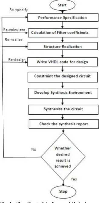
Flow Chart for designing the high speed and low power FIR filter is shown in figure 3.1.
Fig. 4. Flow Chart of the Purposed Method Fig. 5.
The steps for designing the high speed and low power FIR filter algorithm is as follows:-
Filter Specification: This may include stating the type of filter, for example low-pass filter, the desired amplitude and/or phase responses and the tolerances, the sampling frequency, the word length of the input data. In this thesis we are using band pass filter.
Filter Coefficient Calculation: The coefficient of a transfer function h(z) is determined in is this step, which will satisfy the given specifications. The choice of coefficient calculation method will be influenced by several factors and the most important are the critical requirements i.e. specification. The window, optimal and frequency sampling method are the most commonly used.
Realization: This involves converting the transfer function into a suitable filter network or structure. In this thesis parallel pipelined structure is used.
IV.RESULTS
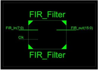
Fig. 6. Schematic Diagram of Band-pass Filter.
Advanced HDL Synthesis Report of parallel pipelined FIR Filter Using Radix-16 Multiplier is shown in figure 4.2.
Fig. 7. Advanced HDL Synthesis Report pipelined FIR Filter Using Radix-16 Multiplier
Register Transfer Level (RTL) Schematic and Technology Schematic of FIR filter is shown in figure 4.3 and figure 4.4 respectively.
Fig. 8. Register Transfer Level (RTL) Schematic
Fig. 9. Technology Schematic
Birinderjit Singh Kalyan 124
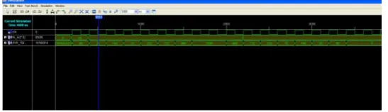
Fig. 10.Simulation Waveform
V.CONCLUSIONANDFUTURESCOPE
The FIR filters are extensively used in digital signal processing and can be implemented using programmable digital processors. With the advancement in Very Large Scale Integration (VLSI) technology as the DSP has become increasingly popular over the years, the high speed realization of FIR filters with less power consumption has become much more demanding. Since the complexity of implementation grows with the filter order and the precision of computation, real-time realization of these filters with desired level of accuracy is now becoming a challenging task The design of pipelined FIR filter using the encoding schemes Radix-16 are carried out via Hardware Description Language. Simulation and synthesis for FPGAs are accomplished on XILINX ISE Software (Xilinx ISE 12.4 version). In future the simulated work can be interfaced with A/D and D/A converter and he optimization of the design can be done in terms of area occupied on chip.
VI.REFERENCES
[1] S. K. Mitra, “Digital Signal Processing”, New York: Tata McGraw Hill, 2005. [2] Prabhat Ranjan,” Implementation of FIR filter on FPGA”, 2008.
[3] S. W. Smith, “The Scientist and Engineer's Guide to Digital Signal Processing”, San Diego: California Technical Publications, 1997.
[4] Abdul Qayyum and Moona Mazher, “Design of Programmable, Efficient Finite Impulse Response Filter Based on Distributive Arithmetic Algorithm”, International Journal of Information Technology and Electrical Engineering, Volume 1, Issue 1, December 2012.
[5] L. Tan, and J. Jiang, “Digital Signal Processing: Fundamentals and Applications”, Amsterdam: Academic Press, 2007. [6] K. K. Parhi, VLSI Digital Signal Processing Systems: Design and Implementation. New York: John Wiley & Sons, Inc., 1999. [7] http://en.wikipedia.org/wiki/Digital_filter
[8] X. Jiang, and Y. Bao, “FIR filter design based on FPGA”, International Conference on Computer Application and System Modeling, pp. 621-624, 2010.
[9] R. A. Barapate, “Digital Signal Processing”, Pune: Tech-Max Publication, 2007.
[10] Kamaraj, C. K. Sundaram, and J. Senthilkumar, “Pipelined FIR Filter Implementation using FPGA”, International Journal of Scientific Engineering and Technology, vol. 1, no. 4, pp. 55-60, Oct. 2012.
[11] R. Kaur, A. Raman, M. H. Singh, and J. Malhotra, “Design and Implementation of High Speed IIR and FIR Filter using Pipelining”, International Journal of Computer Theory and Engineering, vol. 3, no. 2, pp. 292-295, Apr. 2011.
[12] V. A. Pedroni, “Circuit Design and Simulation with VHDL”, Mass.: The MIT press, 2004, pp. 285-293.
[13] V. V. Haibatpure, P. S. Kasliwal, and B.P. Patil, “Performance Evaluation of Proposed Vedic Multiplier in Microwind”, International Journal of Communication Engineering Applications, vol. 3, no. 3, pp. 498-502, Jul. 2012.
[14] P. R. Aparna, and N. Thomas, “Design and Implementation of a High Performance Multiplier using HDL”, International Conference on Computing, Communication and Appilcation, pp. 1-5, 2012.
[15] Kavita and Jasbir Kaur, “Design and Implementation of an Efficient Modified Booth Multiplier using VHDL”, Proceedings of 2nd International Conference on Emerging Trends in Engineering and Management, ICETEM 2013.
[16] P. P. Vaidyanathan, “Optimal Design of Linear-Phase FIR Digital Filters with Very Flat Passbands and Equiripple Stopbands”, IEEE Transactions on Circuits and Systems, vol. 32,no. 9, pp. 904-917, Sep. 1985.
[17] W. S. Lu, A. Antoniou, and S. Saab, “Sequential design of FIR digital filters for low power DSP applications”, Conference Record of the Thirty-First Asilomar Conference on Signals, Systems &, IEEE, pp. 701-704, 1997.
[18] Y.P. Lin, and P. P. Vaidyanathan, “A Kaiser Window Approach for the Design of Prototype Filters of Cosine Modulated Filterbanks”, Signal Processing Letters, IEEE, vol. 5, no. 6, pp. 132-134, Jun. 1998.
[19] A. Kuncheva, and G. Yanchev, “Synthesis and Implementation of DSP Algorithms in Advanced Programmable Architectures”, International Scientific Conference Computer Science, pp. 153-157, 2008.
[20] P. K. Meher, S. Chandrasekaran, and A. Amira, “FPGA Realization of FIR Filters by Efficient and Flexible Systolization Using Distributed Arithmetic”, IEEE Transactions on Signal Processing, vol. 56, no. 7, pp. 3009-3017, Jul. 2008.
[21] N. H. Phuong ,“ The FIR Filter Design : The Window Design Method”, 2009.
[22] Anshika Rajolia,Maninder Kaur, “Finite Impulse Response (FIR) Filter Design using Canonical Signed Digits (CSD)”, International Journal of Science and Research (IJSR), Volume 2 Issue 7, July 2013.
[23] https://wiki.ittc.ku.edu/ittc/images/3/37/EECS_140_VHDL_Tutorial.pdf
[24] Birinderjit Singh “Low Power Design Consideration & Power Dissipation in CMOS IC”, International Conference , ICSCI, Hyderabad 26th – 27th Jan 2010.
[25] Birinderjit Singh, “Comparative Analysis of Small Signal and Large Signal parameters in Heterostructure Field Effect Transistors” IJCA Proceedings on National Conference on Structuring Innovation Through Quality SITQ 2013 SITQ: 4-7, May 2013. Published by Foundation of Computer Science, New York, USA.