ADAPTIVE COLOR FILTER ARRAY INTERPOLATION
ALGORITHM BASED ON HUE TRANSITION AND EDGE
DIRECTION
1E. SREE DEVI, 2 Dr. B. ANAND
1
Rohini College of Engineering and Technology, Department of Electronics and Communication
Engineering, Variyoor Post, Kaniyakumari District, INDIA
2Hindusthan College of Engineering and Technology, Department of Electrical and Electronics
Engineering, Coimbatore, INDIA
E-mail: [email protected]
ABSTRACT
Most of the digital cameras used now has single sensor with an array of color filters to capture the digital images. Color Filter Array (CFA) uses alternating color filters to sample only one color of a pixel location to reduce the price. In the entire image, only one third of sampled pixels have genuine values from the sensors. Remaining pixels are interpolated from these genuine values. In this work, a new adaptive CFA interpolation model is proposed. Pixels are divided into edge pixels and non-edge pixels. If the pixel is not in an edge, then smooth hue transition interpolation is used. For the pixels in the edge, Edge sensing interpolation algorithm is used. A mathematical model is proposed for interpolation based on the direction of the edges. Two sample images are taken and reconstructed by methods such as hue transition interpolation, edge sensing interpolation and combined approach. PSNR is used to compare the results of proposed technique.
Keywords: CFA Interpolation, Bayer Filter, Hue Transition, Edge sensing, Adaptive Interpolation Algorithm
1. INTRODUCTION
To capture the images in a digital camera, Charge-Coupled Device (CCD) or Complementary Metal-Oxide Semi-conductor (CMOS) sensor is used to sense the intensity of the reflected light incident on the sensor. There are three primary colors such as Red (R), Green (G) and Blue (B) are used to mention the color of a pixel. Therefore, three sensors are required for capturing the primary colors at each pixel location. In most of the image capturing devices, the region colors are captured with one sensor and an array of color filters by using Color Filter Array (CFA) is used to reduce the cost and packaging. CFA acts as a coating on the pixel of the sensor array that allows the photons of one color component and blocks the photons of other two color components [1]. Therefore, these color filters are used to separate the light from the sensor according to the wave lengths. Wave length of the light decides the intensities at each pixel location. Therefore, CFA generates the sub sampled color image [2]. In the entire image, only one third
of captured pixels have genuine values from the sensors. Remaining pixels are interpolated from these genuine values [3]. CFA uses alternating color filters to sample only one color of a pixel location.
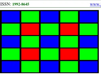
There are many number of CFA patterns used in different types of digital cameras. Some of the patterns are Bayer Filter, RGBE filter, CYYM, CYGM and so on. Widely used pattern for CFA is the Bayer pattern [4]. Bayer pattern has Blue and Red filters in the alternating locations of the pixels both in the horizontal and vertical directions and the green filters are designed in the remaining locations like as quincunx pattern. Our human visual system is very sensitive on the medium wavelength. Extra green filters are useful for accurate sampling at the color band of green.
Therefore Bayer pattern simplifies the
Figure 1: Bayer Pattern CFA Arrangement
1.1 Interpolation
To represent the full color of an image at each pixel, at least 24 bits of color information is needed. Each 8 bits are used for R, G, and B color values. As per the bayer pattern of CFA, only one color is sampled at each pixel. Therefore, to get the missing colors a process called as interpolation is required [6]. Images captured by the digital cameras are having color artifacts when the samples are not estimated properly. All the primary colors such as R, G and B have some common characteristics such as texture and the location of the edges. Also they have similar high frequency components, but their DC components are different. Interpolation gets back the missing values, reduces the artifacts and sharpens the image [7].
For better interpolation, both the intra and inter channel should be correlated by the rules of color ratio and color difference. The major types of CFA interpolation algorithms are adaptive and non-adaptive algorithms. Non non-adaptive interpolation algorithms use simple linear processing and do not use parameter tuning. These algorithms are easier to implement but inefficient by creating blurred images. Nearest neighborhood replication, bi-cubic interpolation and Bi-linear interpolation algorithms are non-adaptive algorithms. Adaptive algorithms use parameter adjustment steps to produce the high quality and sharp looking images. Some of the adaptive interpolation algorithms are edge directed interpolation, edge sensing mechanism, constant hue based, vector SM and directed filtering [8].
In an image, within a homogeneous region transition of hue is smooth from one pixel to nearest pixel. Hue is the ratio between the colors R and G, B and G. Bayer pattern CFA is based on one luminance channel (G) and two chrominance channels (R and B). Hue transition is useful to interpolate pixels within a region. Edge directed
interpolation is an adaptive approach and each pixel is processed based on the surrounding area of the pixel values. Most of the other interpolation algorithms fail on the edges. Edge direction method determines whether interpolation exists in the preferred direction. Interpolation direction is determined to avoid the interpolation across the edges and perform interpolation along with the edges [9]. In this paper, an algorithm is proposed to combine hue based transition interpolation for normal regions and edge directed interpolation method to avoid interpolation across the edges.
2. RELATED WORKS
Jeon [10] conducted experiments with natural images to study the relationship between different size of the color filters and configuration of the colors patterns. Yamanaka patterned CFA was taken with various patterns of three primary colors such as Red, Green and Blue and analyzed with varying sized color filters. Both uploading and downloading samples were used as input for interpolation and results were analyzed. Results proved that Yamanaka pattern CFA gave best objective and subjective performance.
Olivier and Hanqiang [11] presented a new nearest neighborhood interpolation algorithm.
Generally in the nearest neighborhood
interpolation, the missing pixel values of an image were calculated by using the pixel values in the nearest neighbors. This linear method was very useful to give smoother image and speed up the processing. To improve the resolution of the outcome of the interpolated image, proposed method in this paper assigned weightage to the neighborhood pixels that resulted high quality images. Peak Signal to Noise Ratio was used to compare the performance with conventional methods. PSNR was high for the proposed nearest neighborhood algorithm.
step, bilinear interpolation for the luminance components was done.
Zhang et al., [13] presented a Robust Color Demosaicking with Adaptation to Varying Spectral Correlations. Most of the interpolation algorithms used the correlation among the primary colors used in the CFA pattern. But in the image captured by the sensors might have low or no correlation in some locations that lead to interpolation errors. These types of errors were visually identifiable. To solve this problem, in this paper a hybrid interpolation algorithm was proposed. Missing pixel values are predicted based on the linear minimum square estimation and support vector regression. This method gave high quality images by removing the worst type of artifacts produced by the conventional interpolation algorithms.
Menon and Calvagno [14] presented a set of
regularization approaches to demosaicking.
Regularization approaches could be used in interpolation by using the prior knowledge about the color bands of the images to improve the interpolation in the edges and pixels where there were discontinuities. The knowledge such as
correlation between primary color bands,
smoothness of the pixels could be used for interpolation. The proposed regularization approach was evaluated by the Color Peak Signal to Noise Ratio (CPSNR). Results showed that proposed algorithm gave high CPSNR when comparing to
the computationally demanding interpolation
algorithms.
Dargah and Deshpande [15] suggested the need of smooth hue transition interpolation. Smooth hue transition was the extended interpolation method of bilinear interpolation method. When the hues of adjacent pixels varied suddenly or abruptly, then bilinear interpolation produced high interpolation errors. To avoid in the RGB primary color pattern, red hue and blue hue was calculated and used for interpolation.
Aelterman et al [16] presented an efficient locally adaptive demosaicing of color filter array images using the dual-tree complex wavelet Packet transform. Most of the interpolation algorithms suffered from the computational costs. In this work, instead of interpolating the actual pixel values, wavelet transform was done on the raw images.
Then resulting wavelet coefficients were
interpolated. Resulting image was noise free, de blurred and demosaiced image. Therefore high quality image was achieved at low computational cost.
CFA interpolation was an essential step in the image processing of cameras having single sensors. To improve the quality of interpolated images many algorithms were proposed in the literature. Pekkucuksen and Altunbasak [17] proposed a Gradient based threshold free color filter array interpolation. This was a linear interpolation algorithm to reduce the mean square error by using the gradient values calculated from the pixels. PSNR was used to evaluate the performance with other conventional interpolation methods. Proposed method gave images with very good visual quality with high PSNR.
Earlier methods of interpolation suffered from the blurring, zipper artifacts around the pixels present in the edges. A new edge sensing method was proposed by Chung and Chan [18] by calculating integrated gradients (IG). In the raw image, both in the domains of color intensity and color difference the gradient measures were calculated and used for interpolation. Integrated gradient was used as an edge detector and determined the direction of edges to avoid the interpolation across the edges, because the human visual system is very sensitive to the interpolation done across the edges. From the bayer pattern input images, weaker integrated gradient was calculated. Then integrated gradient was extracted for color intensity and color difference domains. Based on IG, interpolation was done for green components. After that interpolation for red and blue components of all the pixels were done. Performance was evaluated by using CPSNR and the number of arithmetic operations needed per pixel. Simulation results showed that proposed edge sensing method used 80 arithmetic operations per pixel and CPSNR is 20 to 40 % higher than interpolation methods such as HPHD, DCMSE and VCD demosaicking algorithms.
formulas. Let I(x,y) represented original image and I^(x,y) represented the interpolated image.
( ) ( )
(
)
11 1 2 2
0 0
1 ˆ
, ,
* m n
x y
RMSE I x y I x y
m n
− −
= =
= −
∑ ∑
10
20 * log MAXI
PSNR
RMSE
=
3. METHODOLOGY
In the proposed CFA interpolation, all the pixels are divided into normal pixels and pixels in an edge. If the pixel is not in an edge, then smooth hue transition interpolation is used. In HVS, system red hue is defined as a ratio between Red and Green colors and Blue hue is defined as a ratio between Blue and green color. When doing interpolation missing blue value is calculated by the following cases [1, 21].
Case 1: If pixel at a location (m, n) has only green value and adjacent right and left pixels have the component of blue color, then information of blue color component at the location(m, n) is calculated by,
, 1 , 1
, ,
, 1 , 1
* m n m n / 2 m n m n
m n m n
B B
B G
G G
− + − +
= +
Case 2: If pixel at a location (m, n) has only green value and adjacent top and bottom pixels have the component of blue color, then information of blue color component at the location(m, n) is calculated by,
1, 1,
, ,
1, 1,
* m n m n / 2 m n m n
m n m n
B B
B G
G G
− + − +
= +
Case 3: If pixel at a location (m, n) has only red value, then four diagonals will be blue color. Then blue color at location (m, n) is calculated by
1, 1 1, 1 1, 1 1, 1
, ,
1, 1 1, 1 1, 1 1, 1
* m n m n m n m n / 4
m n m n
m n m n m n m n
B B B B
B G
G G G G
− − − + + − + +
− − − + + − + +
= + + +
Similarly missing red values can be calculated. For the detection of pixels at an edge the filters such as sobel and canny is used. But they are not useful to represent the transition of luminance or
sharpness which is essential to perform
interpolation. Edge transition based interpolation is
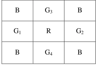
useful to avoid the interpolation across the edges and perform interpolation along the direction of edges. In this paper, at each pixel of an edge, depending on the correlation of surrounding pixel a mathematical model is proposed. It defines two scenarios one for horizontal directed edge and another for vertical directed edge. Direction is determined by referring the next pixel in the edge [20]. The proposed mathematical model is explained by using the example in figure 2. Assume that R is the missing component.
B
G
3B
G
1R
G
2 [image:4.612.336.497.226.334.2]B
G
4B
Figure 2: Example to find missing Component R
In the horizontal scenario, If G1 > G2 then
R=0.075 G1 + 0.025G2.
If G3 > G4 ,then
R=0.075 G3 + 0.025G4
In the vertical scenario, If G3 > G4, then
R=0.075G1+0.025G2+0.75G3+0.25G4
4. EXPERIMENTS AND RESULTS
In this work, a new adaptive CFA interpolation model is proposed. For the pixels in the normal regions of an image Hue transition interpolation technique is used whereas for the pixels in the edge region the proposed mathematical model using edge sensing is used. Figure 3 and 4 shows the sample image taken and interpolated image respectively. Figure 5 and 6 shows the original mange and reconstructed image after interpolation. Results are compared for two images by using Peak signal to Noise ratio. PSNR is the subjective quality
comparison method used in interpolation
Table1 PSNR Achieved for various techniques
Image 1
Edge sensing
Smooth Hue
Proposed technique
R 36.24 37.46 35.5593
G 38.34 38.95 42.0991
B 36.1 36.87 38.2460
Image 2
Edge sensing
Smooth Hue
Proposed technique
R 36.47 36.47 35.1746
G 38.42 38.42 42.8812
[image:5.612.108.281.123.328.2]B 35.78 35.78 37.1764
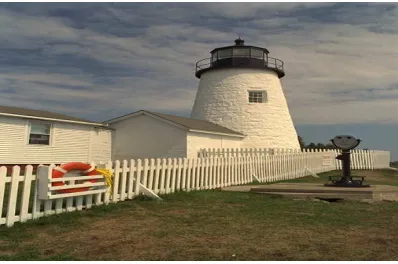
Figure 3: Sample Image 1 before Interpolation
Figure 4: Reconstructed Sample Image 1
For the sample image used in figure 3 proposed method gives average PSNR value of 38.63 for RGB components and hue transition/ edge sensing
[image:5.612.317.520.330.460.2]method gives PSNR of 36.89 and 37.76. The proposed technique achieves 4.72% improvement in the PSNR when compared with Edge sensing method and 2.32% when compared to smooth hue method.
[image:5.612.94.296.371.498.2]Figure 5: Original Sample Image 2 before Interpolation
Figure 6: Sample Image 2 after Interpolation
For the sample image used in figure 5, the proposed method achieves an average PSNR value 38.41 for RGB components and hue transition/ edge sensing method gives PSNR up to 36.89. The proposed technique achieves 4.12% improvement in the PSNR when compared with Edge sensing method and smooth hue method.
5. CONCLUSION
[image:5.612.92.291.538.670.2]model is proposed. For the pixels in the normal regions of an image Hue transition technique is used whereas for pixels in the edge the proposed mathematical model is used using edge transition information. Two sample images are taken and reconstructed by hue transition interpolation, edge sensing interpolation and combined approach as proposed. PSNR is used to compare the results of proposed technique. Combined approach produced images with high visual quality and increased PSNR than applying edge sensing and hue transition interpolations separately.
REFRENCES
[1] Ping-Sing Tsai, Tinku Acharya , and Ajay K. Ray “Adaptive Fuzzy Color Interpolation” , Journal of Electronic Imaging Vol. 11(3), July 2002.
[2] Matthias Kirchner, “Efficient Estimation of CFA Pattern Configuration in Digital Camera Images “, Technist Universitat Dresden, Department of Computer Science, 01062 Dresden, Germany.
[3] Robert A. Maschal Jr., S. Susan Young, Joe Reynolds, Keith Krapels, Jonathan Fanning, and Ted Corbin, “Review of Bayer Pattern Color Filter Array (CFA) Demosaicing with New Quality Assessment Algorithms “, Army Research Laboratory, January 2010.
[4] Bayer, B. E. Color Image Array. U.S. Patent 3 971 065, July 1976.
[5] Bahadir K. Gunturk, John Glotzbach, Yucel Altunbasak, Ronald W. Schafer, and Russel M. Mersereau, “Demosaicking: Color Filter Array Interpolation “, 2005.
[6] Lukac, R., & Plataniotis, K. N. (2004). Normalized color-ratio modeling for CFA interpolation. Consumer Electronics, IEEE Transactions on, 50(2), 737-745.
[7] Rudolph J. Guttosch, “Investigation of Color Aliasing of High Spatial Frequencies and Edges for Bayer-Pattern Sensors and Foveon X3 Direct Image Sensors”, www.foveon.com. [8] Rajeev Ramnath, Wesley E. Snyder, Griff
L.Bilbro, “ Demosaicking methods for Bayer Color Arrays “, Journal of Electronic Imaging, 11(3) , 306-315, July 2002.
[9] Gunturk BK, Glotzbach J, Altunbasak Y, Schafer RW, Mersereau RM. Demosaicking: Color Filter Array Interpolation. IEEE Signal Proc Magazine January 2005; 22(1): 44-54. [10] Gwanggil Jeon, “ Filter Size and Color Pattern Investigation for Yamanaka Patterned Color
Filter Array “, International Journal of Smart Home Vol. 7, No. 3, May, 2013.
[11] Rukundo Olivier and Cao Hanqiang , “ Nearest Neighbor Value Interpolation “, (IJACSA) International Journal of Advanced Computer Science and Applications, Vol. 3, No. 4, 2012. [12] Newlin, D. R., & Monie, E. C. (2010). An
Efficient Adaptive Filtering for CFA
Demosaicking. International Journal on
Computer Science and Engineering, 2(04), 954-958.
[13] Fan Zhang, Xiaolin Wu, Xiaokang Yang, ,Wenjun Zhang, and Lei Zhang, “Robust Color Demosaicking With Adaptation to
Varying Spectral Correlations “IEEE
TRANSACTIONS ON IMAGE
PROCESSING, VOL. 18, NO. 12,
DECEMBER 2009.,
[14] D. Menon and G. Calvagno, “Regularization approaches to demosaicking,” IEEE Trans. Image Process., vol. 18, no. 10, pp. 2209– 2220, Oct. 2009.
[1] [15] Nick Dargahi, Vin Deshpande, “ New
Methods in Bayer Demosaicking Algorithms”, Applied Vision & Image Systems Engineering, September 2009.
[16] Aelterman J, Goossens B, De Vylder J,
Pižurica A, Philips W, “ Computationally Efficient Locally Adaptive Demosaicing of Color Filter Array Images Using the Dual-Tree Complex Wavelet Packet Transform.” , PLoS ONE 8(5): e61846, 2013.
[17]I. Pekkucuksen and Y. Altunbasak, “Gradient based threshold free color filter array interpolation,” in Proc. IEEE Int. Conf. Image Process., Sep. 2010, pp. 137–140.
[18] K. H. Chung and Y. H. Chan, “Low-complexity color demosaicing algorithm based on integrated gradients,” J. Electron. Imag., vol. 19, no. 2, p. 021104-1-15, Jun. 2010. [19] Angelos Amanatiadis and Ioannis Andreadis,
“A survey on evaluation methods for image interpolation” , September 2009.
[20] L.Naveen, B.Shobanbabu, ”Color Filter Array Interpolation for Edge Strength Filters “, International Journal of Engineering Trends and Technology (IJETT) - Volume4 Issue7- July 2013.
[21] David R Cok, "Signal processing method and
apparatus for producing interpolated