International Journal of Emerging Technology and Advanced Engineering
Website: www.ijetae.com (ISSN 2250-2459, ISO 9001:2008 Certified Journal, Volume 2, Issue 12, December 2012)
246
Optimum Diameter of Tapered Elevated RC Water Tank Staging
Chirag N. Patel
1, H. S. Patel
21Ph.D. Candidate, Faculty of Engineering, Pacific Academy of HigherEducation and Research University, Udaipur, Rajasthan,
India. 2
Associate Professor, Applied Mechanics Department, L. D.College of Engineering Ahmedabad, Gujarat, India.
Abstract— Water tank is used extensively for storing water, inflammable liquids and other chemicals. Generally, to provide water at large, tank is supported on frame or shaft (a vertical cylindrical shell). The staging with a single row of columns placed straight (vertical) along the periphery of circle or shaft, are generally adopted for elevated water tanks to support the tank container. Apart from verticality of staging, tapered (inclined) staging are also used to support the tank container. The aim of this paper is to understand the behavior of elevated water tank with frame and shaft type tapered staging in lateral earthquake loading using GSDMA guide line [6] and software SAP2000 [8]. The study have been assess, the optimum diameter of staging with reference to the diameter of container, and observed effect of staging batter. The study reveals that value of axial tension decreases with increase in tapering of staging as well as increase in diameter of staging. Optimum dimension of staging to fulfill the requirement of 'No Tension in column’ is with 70% and 80% diameter of staging in comparison with the container diameter for frame and shaft type staging respectively, in accordance with inclination of 6°.
Keywords— Water, Intze Tank, Tapered Staging, Two mass model, Sloshing height
I. INTRODUCTION
Water is the prime necessity for survival. All around the globe, human civilization has developed on the fertile banks of rivers and large natural lakes. Liquid storage tanks are used extensively by municipalities and industries for storing water, inflammable liquids and other chemicals. Thus Water tanks are very important for public utility and for industrial structure having basic purpose of to secure constant water supply at the longer distance with sufficient static head to the desired destination under the effect of gravitational force. The overhead tanks which have been the inevitable part of water supply system, by the help of which the required water head can easily be achieved to erecting it on purpose made supporting towers and water can be made available to all by the action of gravity. It is also essential to ensure that, requirements such as water supply is not hampered during an earthquake and should remain functional in the post-earthquake period. In such situations the elevated tanks may prove most handy tool for the purpose of water distribution and fire protection.
In some water retaining structures distress has been observed even in 9 to 10 years of service life due to some problems related to structural aspects [1]. During the past earthquakes, tanks have suffered varying degree of damages, including buckling of ground supported slender tanks (Malhotra, 1997), rupture of steel tank shell at the location of joints with pipes, collapse of supporting tower of elevated tanks (Manos and clough, 1983, Rai, 2002), cracks in the ground supported RC tanks, etc. Water tanks can experience distress due to several reasons such as improper structural configuration design, inferior
materials, inferior workmanship, corrosion of
International Journal of Emerging Technology and Advanced Engineering
Website: www.ijetae.com (ISSN 2250-2459, ISO 9001:2008 Certified Journal, Volume 2, Issue 12, December 2012)
247
In recent past earthquakes Bhuj, Gujarat (2001) and Jabalpur (1997) thin shell of circular shaft have perform unsatisfactory, thin shaft shell when used as a column (or pedestal) are vulnerable because they not only possess a very low ductility but also lack redundancy of alternate load path that are present in framed structure. Supporting structure, especially the staging of an elevated water tank does not have much redundancy. This lack of redundancy is extremely serious in circular shaft type staging where lateral stability depends only on the shaft. For structure in high Seismicity regions earthquakes loading is considered the most significant and possibly the most destructive external loads, particularly for low to medium rise tanks. The poor performance of such critical facilities during recent seismic events in the country required careful scrutiny of their designs, construction quality and their post-earthquake performance. The frame and shaft type support system of elevated water tank should have an adequate strength to resist axial loads, moment and shear force due to lateral loads. These forces depend upon total weight of the structure, which varies with the amount of water present in the tank container. In extreme case, to avoid the total collapse, importance of seismic analysis of liquid storage tanks does not need any over emphasis. In recent years the number, the size and importance of these structure have been increased and there is need to understand their seismic behavior and to formulate rational and efficient method of their analysis and design to resist earthquake ground motion. This necessitates the overhead tanks to be designed safe to the required degree against all possible forces expected to be encountered during its life time economically.
In current Indian code for seismic design, limited provisions on seismic design of elevated tanks are given. Those provisions are highly inadequate compared to present international practice. Most of the previous studies were focused on the tank containing liquid considering only one mass and it does not cover important aspects for analysis and design of water tanks related to the effect of hydrodynamic pressure of the water, which produce due to vibration of the tank when earthquake strikes. But, After the Bhuj earthquake, revision of current Indian code became inevitable. Hence it was decided to develop guidelines under the project ―Review of Building Codes and Preparation of Commentary and Handbooks‖ assigned by the Gujarat State Disaster Management Authority (GSDMA), Gandhinagar to the Indian Institute of Technology Kanpur in 2003. The draft code for liquid retaining structures is one of the outcomes of the project.
Indian Institute of Technology, Kanpur has proposed guidelines along with commentary and explanatory examples for seismic analysis of liquid storage tanks in association with GSDMA (Gujarat State Disaster Management Authority) [6]. These publications cover seismic analysis and design of ground supported as well as elevated tanks. At present, IS 1893: 1984 describes the seismic force criteria for elevated water tanks, which does not count the convective hydrodynamic pressures in the analysis of water tank and assumes the tank as a single degree of freedom idealization. Whereas, in the guideline considered; two degree of freedom idealization taking into account impulsive as well as convective hydrodynamic forces for realistic evaluation of dynamic properties of tanks. Also, from past earthquakes it has been observed that, the current designs of supporting structures of elevated water tanks are tremendously vulnerable under lateral forces and the Bhuj (India) earthquake provided another illustration when a great number of water tanks with frame staging suffered damage and a few collapsed [7].
The present study is an effort to identify the optimum diameter of tapered elevated water tank staging under full condition considering two-mass model by impulsive and convective water masses inside the container using structural FE software SAP 2000.
II. CONSIDERATION OF GSDMAGUIDELINE
This guideline has been prepared in accordance with generally recognized engineering principles and practices. Many international codes, standards and guidelines have been referred. Seismic analysis of water tanks considering hydrodynamic effect has been explained in detail. Following important provisions and changes have been incorporated as compared to that of IS 1893:1984.
Analysis of ground supported tanks.
For elevated tanks, the single degree of freedom is replaced by two degree of freedom idealization.
Bracing beam flexibility is explicitly included in calculation of lateral stiffness of tank staging.
The effect of convective and impulsive
hydrodynamic pressure distribution in the analysis.
Effect of vertical ground acceleration on
hydrodynamic pressure and pressure due to wall inertia.
Sloshing effect of water and maximum sloshing
wave height.
International Journal of Emerging Technology and Advanced Engineering
Website: www.ijetae.com (ISSN 2250-2459, ISO 9001:2008 Certified Journal, Volume 2, Issue 12, December 2012)
248
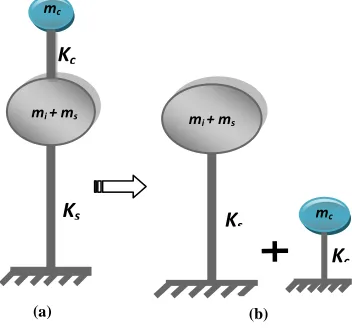
[image:3.612.77.253.347.515.2]Hydrodynamic effect is considered by dividing water into two different masses, namely impulsive and convective. When the tank containing liquid with free surface is subjected to horizontal earthquake ground motion, tank wall and liquid are subjected to horizontal acceleration. The liquid in the lower region behaves like a mass that is rigidly connected to the tank wall. This mass is termed as impulsive liquid mass, which, accelerates along with the wall and induces impulsive hydrodynamic pressure on tank wall and on base. The liquid mass in the upper region of tank undergoes sloshing motion. This mass is termed as convective liquid mass and exerts convective hydrodynamic pressure on wall and base. For representing these two masses and in order to include the effect of their hydrodynamic pressure in analysis, spring mass model is adopted for ground-supported tanks and two-mass model for elevated tanks.
Figure 1. Two mass model for elevated tanks
In spring mass model convective mass (mc) is attached
to the tank wall by the spring having stiffness Kc, whereas
impulsive mass (mi) is rigidly attached to tank wall. For
elevated tanks two-mass model is considered, which consists of two degrees of freedom system. Spring mass model can also be applied on elevated tanks, but two - mass model idealization is closer to reality. The two - mass model is shown in Figure 1. where, mi, mc, Kc, hi, hc, hs,
etc. are the parameters of spring mass model and charts as well as empirical formulae are given for finding their values. The parameters of this model depend on geometry of the tank and its flexibility.
For elevated tanks, if the shape is other than circular or rectangular, then the values of spring mass parameters can be obtained by considering an equivalent circular tank having same capacity with diameter equal to that of diameter at top level of liquid in original tank.
The two-mass model was first proposed by G. M. Housner and is being commonly used in most of the international codes. The response of the two-degree of freedom system can be obtained by elementary structural dynamics. However, for most of elevated tanks it is observed that both the time periods are well separated. Hence, the two-mass idealization can be treated as two uncoupled single degree of freedom system as shown in Figure 1 (b). The stiffness (Ks) shown in Figure 1 is lateral
stiffness of staging. The mass (ms) is the structural mass
and shall comprise of mass of tank container and one-third mass of staging as staging will acts like a lateral spring. Mass of container comprises of roof slab, container wall, gallery if any, floor slab, floor beams, ring beam, circular girder, and domes if provided.
III. PROBLEM DESCRIPTION
[image:3.612.329.556.416.605.2]A. Frame Type Staging
Figure 2. Plan and elevation of tapered frame type staging
The numbers of columns considered in the study are six symmetrically disposed on a circle. Bracings are considered as straight and provided at three levels with each of 4 m spacing, thus dividing the staging in four column panels.
K
smi + ms
mc
K
c
a)
(
a
)
T
w
o
K
smi + ms
mc
K
cInternational Journal of Emerging Technology and Advanced Engineering
Website: www.ijetae.com (ISSN 2250-2459, ISO 9001:2008 Certified Journal, Volume 2, Issue 12, December 2012)
249
[image:4.612.327.556.119.561.2]The bottom panel is numbered 1 and the top panel is numbered 4. Top ends of the columns are connected by a ring beam and the bottom ends of the columns are connected to the foundation ring beam they are assumed to be fixed for the analysis. The inclination of columns to the vertical is 0°, 3° and 6° is considered, where staging diameter at top level is about 60%, 70% and 80% in comparison with diameter of container. The schematic diagram for 70 % diameter with frame type staging is as shown in Figure 2.
Figure 3. Water tank with frame type staging
TABLEI
STRUCTURAL DATA OF WATER TANK
Numerical Data of the Tank Data
Capacity of the tank, 250 m3 Unit weight of concrete, 2500 kg /m3
Intze Tank Container Data
Thickness of Top Dome 0.12 m Rise of Top Dome, 1.7 m Size of Top Ring Beam, 0.25 x 0.30 m Diameter of tank 8.8 m Height of Cylindrical wall 4.0 m Thickness of Cylindrical Wall, 0.2 m Size of Middle Ring Beam, 0.50 m x 0.30 m Rise of Conical dome 1.5 m Thickness of conical dome 0.25 m Rise of Bottom dome 1.30 m Thickness of Bottom dome shell 0.20 m
Numerical data for frame
staging
Number of bracings 3 Number of columns 6 and 8 Size of Bottom ring Beam 0.50 m x 0.60 m Distance between intermediate
Bracing 4.00 m
Height of staging above
foundation 16.30 m
Radius of circle formed at ring
beam (at 0°) 3.14 m Batter in column with vertical 0°, 3° and 6° Diameter of columns 0.65 m Size of bracing 0.30 m x 0.60 m
Earthquake Zone 4
Soil Condition Hard Type
S.B.C. 300 kN/m3
B. Shaft Type Staging
Figure 4. Plan and elevation of tapered shaft type staging
[image:4.612.98.237.262.480.2] [image:4.612.326.560.340.546.2]International Journal of Emerging Technology and Advanced Engineering
Website: www.ijetae.com (ISSN 2250-2459, ISO 9001:2008 Certified Journal, Volume 2, Issue 12, December 2012)
[image:5.612.95.250.130.381.2]250
Figure 5. Water tank with shaft type staging
TABLEII
STRUCTURAL DATA OF WATER TANK
Numerical Data of the Tank Data
Capacity of the tank, 250 m3
Unit weight of concrete, 2500 kg /m3
Intze Tank Container Data
Thickness of Top Dome 0.12 m
Rise of Top Dome, 1.7 m
Size of Top Ring Beam, 0.25 x 0.30 m
Diameter of tank 8.8 m
Height of Cylindrical wall 4.0 m
Thickness of Cylindrical Wall, 0.2 m
Size of Middle Ring Beam, 0.50 m x 0.30 m
Rise of Conical dome 1.5 m
Thickness of conical dome 0.25 m
Rise of Bottom dome 1.30 m
Thickness of Bottom dome shell 0.20 m
Numerical data for shaft staging
Size of Bottom ring Beam 0.50 m x 0.60 m
Height of staging above foundation 16.00 m Radius of circle formed at ring beam
(at 0°) 3.14 m
Batter in column with vertical 0°, 3° and 6°
Thickness of Shaft 0.20 m
Earthquake Zone 4
Soil Condition Hard Type
S.B.C. 300 kN/m3
In such cases as per GSDMA guide line [7] an alternate load combination rule can be used. As mentioned staging components can be designed for 100% + 30% rule. In which earthquake load should applied like 100% load in X direction plus 30% of the load in the Y direction, both acting together and same for, both the direction with tank full condition. As mentioned above various load combination Earthquake-X x) and Earthquake-Y (EQ-y) replaced with following load combination.
(± ELx ± 0.3ELy) and (± ELy ± 0.3ELx)
[image:5.612.335.552.354.475.2]Where x and y are two orthogonal horizontal directions, earthquake load (E.L.). Value of vertical loads due to self- weight of container, water and live load found out analytically and applied in 3-D skeletal in SAP 2000 software as shown in Figure 6 and 8 while most critical value of horizontal base shear from earthquake force has been found out and applied on Center of gravity node of tank connected by rigid link as shown in Figure 7 and 9.
Figure 6. Application of Self Weight and Water -Dead Load
[image:5.612.64.276.416.709.2]International Journal of Emerging Technology and Advanced Engineering
Website: www.ijetae.com (ISSN 2250-2459, ISO 9001:2008 Certified Journal, Volume 2, Issue 12, December 2012)
251
[image:6.612.61.553.114.638.2]Figure 7. Application of Base Shear in X - direction
[image:6.612.96.240.437.581.2]Figure 8. Application of Self Weight and Water -Dead Load
Figure 9. Application of Base Shear in X – direction
IV. RESULTS AND CONCLUSIONS
Figure 10. Axial Tension/Compression in frame Staging
Value of axial tension decreases with increase in tapering of staging as well as increase in diameter of staging.
Maximum pressure will increases with increase in tapering in staging but minimum pressure will decrease.
Results show except 5.28 m (60%) diameter with 3°
and 6° tapering, in all other cases, will fulfill the stability requirements.
Optimum dimension of staging with 'No Tension in column and 'No uplift and No Tension' in foundation is 70% (6.28 m) with 6° inclination or 80% (8.04m) with 0° inclinations.
[image:6.612.338.551.476.611.2]International Journal of Emerging Technology and Advanced Engineering
Website: www.ijetae.com (ISSN 2250-2459, ISO 9001:2008 Certified Journal, Volume 2, Issue 12, December 2012)
252
Value of axial tension decreases with increase intapering of shaft as well as increase in diameter of shaft.
Maximum pressure will increase with increase in tapering in staging but minimum pressure will decrease.
Optimum dimension of staging based on minimum
tension in shaft and footing but no uplift is 80% (7.04 m) with 6° inclination.
REFERENCES
[1] Amjad Masood, Tazyeen Ahmad, Muhammad Arif and V. P. Mital, ―Failure of Overhead Water Tank in the State of Uttar Pradesh in India – A Case Study‖, ICCIDC-I, August -2008, Vol-1, Pg. 185-191.
[2] Sudhir Singh Bhadauria and Mahesh Chandra Gupta, ―In-Service Durability Performance of Water Tanks‖, Journal of Performance of Constructed Facilities, ASCE, May – 2006, Vol-2, Pg. 136-145.
[3] Sudhir Singh Bhadauria and Dr. Mahesh Chandra Gupta, ―In Situ Performance Testing of Deteriorating Water Tanks for Durability Assessment‖, Journal of Performance of Constructed Facilities, ASCE, May/June – 2007, Vol-3, Pg. 234-239.
[4] Durgesh C. Rai, ―Performance of elevated tanks in Mω7.7 Bhuj earthquake of January 26th, 2001‖, Proc. Indian Acad. Sci., September – 2003, Vol-3, Pg. 421-429.
[5] BIS 1984 IS: 1893-1984 Criteria for earthquake resistant design structures, Bureau of Indian Standards, New Delhi.
[6] IITK-GSDMA Guidelines for Seismic Design of Liquid Storage Tanks Provisions with commentary and explanatory examples. [7] Chirag N. Patel and H. S. Patel, ―Former Failure Assessments of RC
Elevated Water Tanks: Literature Review‖, GIT-Journal of Engineering and Technology (ISSN 2249 - 6157), 2012.