© 2017, IRJET | Impact Factor value: 6.171 | ISO 9001:2008 Certified Journal | Page 297
SPEED CONTROL AND PARAMETER VARIATION OF INDUCTION MOTOR
DRIVES USING FUZZY LOGIC &ADRC CONTROLLERS
M.ANKARAO
1, S.ANUSHA
2, C.SIREESHA
31
Asst.professor,Dept.of. Electrical & Electronics Engineering,JNTUACEA,Anantapuramu,A.P,.India
2 Department of Electrical and Electronics Engineering, JNTUACEA,College of Engineering, Ananthapuramu,
3
Student, Dept. of Electrical & Electronics Engineering, JNTUACEA,Anantapuramu, A.P.,India.
---***---Abstract -
A novel robust control scheme employing threefirst order auto-disturbance rejection controllers was presented for the speed control of induction motor drives. In this paper the dynamic performance of the induction motor is compared using the ADRC and FUZZY controllers. The fuzzy controller has the better performance characteristics. The simulation results show that the proposed control scheme can cope with the internal disturbance and external disturbance, such as the motor’s parameter variations, the load disturbances, etc. The simulation results shows the effective performance of the proposed method compared with the conventional method that is by using ADRC controllers. The simulation is carried out using MATLAB/SIMULINK model.
Key Words: Auto-disturbance rejection controller (ADRC), Induction motor, robust control, vector control, fuzzy logic controllers.
1.INTRODUCTION
In induction motors also have a chance to be controlled as that of dc motors by utilizing the field-oriented control (FOC) (also called as Vector control) approach and the performance of the controlled Induction motors with FOC are almost same to those of dc motors. Of the dc motors with the improvement of the power electronic Components and the high- performance microprocessors Induction engine drives utilizing FOC and convectional Proportional– integral (PI) controllers are being popularized. ADRC based on non-linear structure avoids some inherent defects of classical PID controller. ADRC has better adaptability and robustness. Generally, ADRC is made up of a tracking differentiator (TD) in the feed forward path, an extended state observer (ESO), and a non-linear state error feedback (NSEF).
Due to the low price and ruggedness of induction motors, they have been widely used in many industrial applications. At present, field oriented control (FOC) appears much more attractive due to the capability of torque/flux decoupling which gives high dynamic response and accurate motion profiles . Unfortunately, the high performance of such control strategy is often deteriorated due to significant plant uncertainties. The plant uncertainties, in general, include external disturbances, unpredictable parameter variations, and modeled plant nonlinear dynamics. Standard method of motion control is to use the classic PI controllers
to regulate the static and dynamic performance of control system. The PI controller is usually designed in a linear region ignoring the saturation-type non-linearity. At some working area, the behavior of such controller could be satisfied. When the controller is applied to variable-speed motor drives, the performance deterioration is referred to a windup phenomenon ,which causes large overshoot, slow setting time, and, sometimes, even instability . So the parameters of the PI controller should be modified according to the various operating condition of induction motor. This would add difficulty to the on-line debugging.
Despite this induction motor parameter mismatch or variation with time are the problems associated with the use of conventional PI controllers. And also whenever the load disturbances occurs it has long recovery period. For the most part speaking the necessities of the motor speed control are the accuracy, rapidity and the robustness etc. To fulfill these execution prerequisites there are two ways used by the electrical engineers. One among them is the parameter identification for estimating parameters in FOC. And the second one is the use of the robust controllers instead of pi controllers in order to get better performance. Throughout the past several years many parameter identification techniques have been proposed. Because of this we need to calculate so many parameters. So this increases the complexity of the algorithm.
For all the above cases the rotor flux estimator is used. Because of this it requires more memory and more run time. In order to avoid this the proposed method does not requires the rotor flux estimation. This paper consists of three first order ADRC controllers. One controller is used for control of speed. One for quadrature axis current. And the other one for direct axis current.
2. CLOSED LOOP SPEED CONTROL OF INDUCTION
MOTOR USING THREE FIRST ORDER ADRC
© 2017, IRJET | Impact Factor value: 6.171 | ISO 9001:2008 Certified Journal | Page 298
Now the proposed method consists of three ADRC’s
which are of first order for speed control. For the direct and quadrature axis current. As we are using only the first order ADRC,s for these controls which includes the speed control , direct axis current, quadrature axis current the runtime required is reduced. And also the memory requirement for the estimation of flux is also reduced. And also as the proposed system consists of only low order ADRC’s the complexity required is also less. To improve the performance of field oriented control of induction motor, a new nonlinear auto-disturbance rejection controller is adopted. This system consists of three parts: tracking differentiator (TD), extended state observer (ESO) and nonlinear state error feedback control law. Using the nonlinear state feedback, ESO can track satisfactorily the extended state of the system. So it is possible to realize the state feedback and model, external disturbance compensation. Then the nonlinear state error control law is used to make the output converge to input reference signal successfully. Because the design of ADRC is independent of the controlled system model, this controller can manifest its adaptability and robustness not only in some operation area but also in the whole working area.
2.1 TRACKING-DIFFERENTIATOR
Tracking-Differentiator is such a dynamic system that it can arrange the transition process according to the input reference signal.
2.2. EXTENDED STATE OBSERVER
Extended state observer as an elementary unit for ADRC technology is improved so that it can track the system state variable and its derivatives successfully. It is well known that the differential signal often cannot be used because of the existing high frequency noises. But ESO could satisfactorily solve this problem.
2.3. NONLINEAR STATE ERROR FEEDBACK
CONTROL LAW
We could realize modeling uncertainty and disturbance compensation. If the parameters and functions of the ADRC are properly chosen, the state variables have a desired behavior such as tracking, regulation and stability, and the control law u(t)is able to drive the state trajectory to the desired reference signal.
3. SPEED CONTROL USING ADRC FOR INDUCTION
MOTOR
The speed of the induction motor is controlled in the following way by using the speed loop.
ω˙r = k1ψd2iq1 + w1(t)
here the meaning of the terms are as follows. k1 = P2Lm/JL2 and w1(t) = −PTL/J
Ψd2 is the d-axis rotor flux linkage, iq1 is the q-axis stator current, P is the number of pole pairs of the motor, J is the rotor inertia, Lm is the mutual inductance, L2 is the rotor inductance, and TL is the load torque.
The disturbance is mainly the difference in the coupling between the load torque speed loop and the flux loop. The above disturbances can be compensated by using extended state the observer in the ADRC loop.
Fig.1 Proposed method using three first order ADRCs
The fig 1 shows the block diagram for the ADRC system. And the fig 2 shows the basic model of the single ADRC system.
where function fal(e(k), α, δ) is a nonlinear function given as
fal (e(k), α, δ) =
and y(k) is the output signal of the system (plant) to
© 2017, IRJET | Impact Factor value: 6.171 | ISO 9001:2008 Certified Journal | Page 299 Parameters: α1, δ1, β1, and β2. The range of α1 is from 0 to
1; the smaller the α1 is, the better the ability of the ESO against the uncertainty of the induction motor model and the disturbance is. δ1 is the width of linear area of the nonlinear function. The system dynamic performances are affected tremendously by the β1 and β2. β1 mainly has effect on the estimation of the system state, and β2 mainly affects the estimation of the disturbances. The larger the β1 and the β2 are, the faster the estimation converges, on the other hand, if the β1 and the β2 are too large, the estimation might not converge.
The non linear differentiator is given as
where the nonlinear function can be represented by
fst (p1(k), p2(k), r, h0)=
ytd(k)= p1(k)+h0p2(k), a0(k)=( d2+8r )^1/2
d = rh0, d0 = dh0
where
v(k) is the reference signal of the ADRC, for the speed loop,
v(k) is the speed reference ωr (as shown in Fig. 1), x1(k) is the tracking signal of v(k), x2(k) is the derivative of x1(k), also approximately the derivative of v(k), h is the step size.ND is used to arrange transition procedure when tracking the reference signal. There are two adjustable parameters in the ND, i.e., r and h0. r is the convergence rate coefficient. The larger the r is, the faster the procedure that
x1(k) converges to speed wris h0 is a filtering factor used for the noise filtering.
According to the output of the ND and the ESO, the NLSEF gives the control to the corresponding loop
where u(k) is the control output of the ADRC, for the speed loop, u(k) is the q-axis stator current reference
q1 (as shown in Fig. 1). α2 and δ3 possess the similar meanings as that of α1 and δ1 in (2). β3 governs the speed of the system response, however, if β3 is too large, a big overshoot would appear.
3.1. CONTROL OF Q-AXIS CURRENT LOOP
USING ADRC
The mathematical model of the q-axis stator current is
iq1 = −k2iq1 + w2(t) + uq1/Lσ (5)
where
k2 = (R1L22+ R2Lm2)/LσL22
w2(t) = −Lmψd2ωr/LσL2 − id1ω1
Lσ =L1 – Lm2/L2
Here uq1 is the q-axis stator voltage. R1 and R2 are the stator resistance and rotor resistance, respectively. L1 is the stator inductance, Lσ is leakage inductance. ωr is rotor angular speed. ω1 is synchronous angular speed.
3.2. CONTROL OF D-AXIS CURRENT LOOP USING
ADRC
id1 = −k2id1 + w3(t) + ud1/Lσ (6)
where
w3(t) =k3ψd2 + iq1ω1
k3 =R2Lm/LσL22
Here id1 is called as the d-axis current loop, ud1 is the d- axis stator voltage, w3(t) is called the disturbance variable, it is the product of stator speed and q- axis current loop. The disturbance which occurs due to resistance is also taken into consideration.
The ADRC is used to estimate the disturbance value and also adds the required amount of value to compensate that disturbance.
4. SPEED CONTROL OF INDUCTION MOTOR USING
FUZZY LOGIC CONTROLLERS
The speed control of induction motor is also done by using the fuzzy logic controllers instead of ADRC
.
To tackle the load balancing problem, conventional control theory can be applied to restore system equilibrium. Fuzzy logic control attempts to capture intuition in the form of IF-THEN rules, and conclusions are drawn from these rules. Based on both intuitive and expert knowledge, system parameters can be modelled as linguistic variables and their corresponding membership functions can be designed. Thus, nonlinear system with great complexity and uncertainty can be effectively controlled based on fuzzy rules without dealing with complex, uncertain, and error-prone mathematical models. In this paper mamdani model is used for the speed control of induction motor.
© 2017, IRJET | Impact Factor value: 6.171 | ISO 9001:2008 Certified Journal | Page 300 Fig3. Input membership function.
Fig4. Output membership function.
[image:4.595.310.555.56.320.2]Table 1. Control rules for speed control of induction motor.
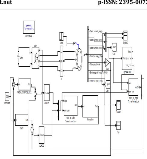
Fig 5. Simulink model for speed control of induction motor using fuzzy logic.
5. SIMULATION RESULTS FOR SPEED CONTROL
OF INDUCTION MOTOR
The simulation results are shown as under. For the simulation here we are using the induction motor which will take power from VSI. And also using the values are given below. MATLAB/SIMULINK model is used. Each one of the ADRC is implemented by using the c-5code. We are using the squirrel cage induction motor the values are as follows.
PN=1.1 kW
UN=380 V
IN=2.67 A FN=50 Hz
R1 =5.27 Ω
R2 =5.07 Ω
Rfe =1370 Ω
L1 =479 mH
L2 =479 mH
Lm=421 mH
σ =0.228
TN=7.45 N · m
P =2
Nn=1410 r/min.
Here checking the performance of the proposed system under the following cases. First one is load disturbance. The second one is the motor parameter variation. And the third one is the model uncertainty. During simulation we are comparing the ADRC values with those values of PI controller.
© 2017, IRJET | Impact Factor value: 6.171 | ISO 9001:2008 Certified Journal | Page 301
5.1. PERFORMANCE DURING LOAD DISTURBANCE
[image:5.595.318.549.51.448.2]Fig 6 gives the simulation results when the load disturbance occurs.fig 7 shows the speed results when the load torque steps up from no load to rated load.fig 6 shows the simulation results when the load torque steps up from full load to no load.
[image:5.595.47.276.174.341.2]Fig 6. From noload to rated load for fuzzy
Fig 7. From rated load to no load for fuzzy
In this paper we are taking the reference speed as 1300rpm. During simulation the values of all the parameters remains constant. As shown in the we observed that the ADRC has the capability to settle to the reference speed after it has experienced some disturbance. But PI controller is not having that capacity.
And also the steady state error for ADRC is low as compared with the PI controller. The steady state error becomes very high in case of PI controller when the load levels increases. It can rise upyo the value of 1.3% of rated load. But if the dynamic ananlysis is taken then PI controller has some what better performance.
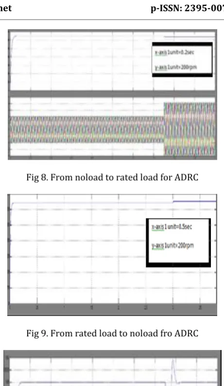
[image:5.595.46.278.372.521.2]Fig 8. From noload to rated load for ADRC
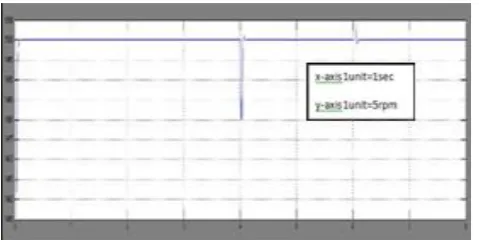
Fig 9. From rated load to noload fro ADRC
Fig.10 Speed of induction motor when load changes from noload to full load using fuzzy logic.
The above fig 10 shows the speed control of induction motor when the load changes from no load to rated load using the fuzzy logic controller. So here by using the fuzzy logic controller the speed response is improved. That is the difference between the reference speed and the actual speed becomes less.
5.2.
PERFORMANCE
WHEN
PARAMETER
VARIATION OCCURS
[image:5.595.319.548.410.541.2]© 2017, IRJET | Impact Factor value: 6.171 | ISO 9001:2008 Certified Journal | Page 302 resistance values we have to use the wound rotor induction
[image:6.595.316.551.129.263.2]motor . but here if we want to use the squirrel cage motor then we will go for step changes in rotor resistance values. Practically the changing of induction motor parameters during the running process is not possible. But in order to know the robustness of the otor during disturbances we are using the step chages in resistance values by using the matlab/simulink model.
Fig.11 Simulation results during the step changes in rotor resistance using ADRC.
Fig.12 Simulation results during the step changes in rotor resistance using fuzzy logic.
The above figure 10 shows the speed of induction motor using fuzzy logic controller. It shows the speed of induction motor when rotor parameter changes. That is it represents the speed of induction motor when rotor resistance changes.
5.3. MODEL UNCERTAINITY PERFORMANCE
Fig 13 shows the model uncertainty performance of the induction motor. That is by considering the iron losses of the machine. Every machine during the designing state compulsory is having the iron losses. So in this case also we are considering the iron losses in the designing stage. In this case we are using the full load torque throughout the operating condition. But here we are not considering the controller design process. For both the controllers the operating conditions are same. Whereas the speed reference steps up from 0.4 to 0.5 at 5 sec. as we know the main advantage of the ADRC is such that if any disturbance occurs it will adjust accordingly and within no time reaches the
[image:6.595.43.280.186.313.2]steady state. The same thing happens in this case also. So comparing this we can say that the ADRC controller is more robust than PI controller.
[image:6.595.318.550.297.439.2]Fig. 13 Model uncertainty performance using FUZZY
Fig.14 Model uncertainty using ADRC
6. CONCLUSION
In this paper a new control strategy using the three first order auto disturbance rejection controllers are used for the robust speed control of induction motor drives. The changes in the speed of the induction motor are studied by varying different parameters like the rotor resistance, and also changing the load from no load to full load. The rotor resistance values are varied in a step manner by using the ADRC controller and the fuzzy controller. The simulation results shows that the by using fuzzy logic controllers the percentage change is about 33.33%.These results shows that the speed changes are less by using the fuzzy controllers compared to ADRC. And also the simulation results shows the robustness of induction motor drive for different parameter variations like load and rotor resistance.
The proposed ADRC controller has the advantage over the PI controller.
[image:6.595.43.283.358.478.2]
© 2017, IRJET | Impact Factor value: 6.171 | ISO 9001:2008 Certified Journal | Page 303
REFERENCES
[1] J. A. Santisteban and R. M. Stephan, “Vector control methods for induction machines: An overview,” IEEE Trans. Educ., vol. 44, no. 2, pp. 170–175, May 2001.
[2] H. A. Toliyat, E. Levi, and M. Raina, “A review of RFO induction motor parameter estimation techniques,” IEEE Trans. Energy Convers., vol. 18, no. 2, pp. 271–283, Jun. 2003.
[3] W. Gaolin, Y. Rongfeng, Y. Yong, C. Wei, and X. Dianguo, “Adaptive robust control for speed sensorless field-oriented controlled induction motor drives,” (in Chinese), Trans. China Electrotech. Soc., vol. 25, no. 10, pp. 73–80, Oct. 2010.
[4] Z. Chunpeng, L. Fei, S.Wenchao, and C. Shousun, “Back-stepping design for robust controller of induction motors,” (in Chinese), Control Decision, vol. 19, no. 3, pp. 267–271, Mar. 2004.
[5] C.-Y. Huang, T.-C. Chen, and C.-L. Huang, “Robust control of induction motor with a neural-network load torque estimator and a neural-network identification,” IEEE Trans. Ind. Electron., vol. 46, no. 5, pp. 990–998, Oct. 1999.
[6] T.-C. Chen and T.-T. Sheu, “Model reference neural network controller for induction motor speed control,” IEEE Trans. Energy Convers., vol. 17, no. 2, pp. 157–163, Jun. 2002.
[7] J. Han, “From PID to active disturbance rejection control,” IEEE Trans. Ind. Electron., vol. 56, no. 3, pp. 900–906, Mar. 2009.
[8] J. Han, “Auto-disturbances-rejection controller and its applications,” (in Chinese), Control Decision, vol. 13, no. 1, pp. 19–23, 1998.
[9] J. Han, “Nonlinear design method for control systems design,” in Proc. 14th Int. IFAC World Congr., Beijing, China, 1999, pp. 230–235.
[10] L. Shunli, Y. Xu, and Y. Di, “Active disturbance rejection control for high pointing accuracy and rotation speed,” Automatica, vol. 45, no. 8, pp. 1854–1860, Sep. 2009.
[11] Y. Zhang, D. Li, and Y. Xue, “Active disturbance rejection control for circulating fluidized bed boiler,” in Proc. 12th ICCAS, Jeju, Korea, Oct. 2012, pp. 1413–1418.
[12] Q. Zhong, Y. Zhang, J. Yang, and J. Wu, “Non-linear auto-disturbance rejection control of parallel active power filters,” IET Control Theory Appl., vol. 3, no. 7, pp. 907–916, Jul. 2009.
[13] Z. Hui, L. Bin, and Y. You-jun, “The auto-disturbance rejection simulation and research of double-fed wind turbine,” in Proc. ICMTMA, 3rd, Jan. 2011, pp. 712–715.
[14] H.-P. Ren, J. Zhang, Q. Li, and D. Liu, “Brushless DC motor speed control based on active disturbance rejection controller,” (in Chinese), Elect. Drive, vol. 38, no. 4, pp. 46– 50, 2008.
[15] H.-P. Ren and F. Zhu, “Optimal design of adaptive disturbance reject controller for brushless DC motor using immune clonal selection algorithms,” (in Chinese), Elect. Mach. Control, vol. 14, no. 9, pp. 69–74, 2010.