ISSN Print: 2329-8421
DOI: 10.4236/ojapr.2019.71001 Mar. 29, 2019 1 Open Journal of Antennas and Propagation
Complementary Split Ring Resonator Loaded
Substrate Integrated Waveguide Leaky Wave
Antenna
Basma M. Yousef
1, Ahmed M. Attiya
2, A. A. Shaalan
31Communications Department, Delta Higher Institute for Engineering and Technology, Mansoura, Egypt 2Microwave Department, Electronics Research Institute, Cairo, Egypt
3Electronics and communications Department, Faculty of Engineering, Zagazig University, Zagazig, Egypt
Abstract
In this paper we present the design of a leaky wave antenna based on Sub-strate Integrated Waveguide (SIW) loaded by Complementary Split Ring re-sonator (CSRR). The proposed antenna is designed for 5G application with a center frequency around 28 GHz. The antenna is implemented on Roger RT/Duriod 5880. The loading CSRRs are designed to resonate at 28 GHz. The design is simulated by using both High-Frequency Simulation Software (HFSS) and Computer Simulation Technology (CST) for verification. Expe-rimental measurements are also presented.
Keywords
Leaky Wave Antennas, MM-Wave, 5G, SIW Antennas
1. Introduction
Leaky Wave Antennas (LWAs) can be described as a fast wave guiding structure with a complex propagation constant. LWAs can be classified into two main categories [1] [2] [3]; uniform guided wave structures [4] [5], and periodic guided wave structures [6] [7] [8] [9]. The uniform leaky-wave antenna can be scanned by varying frequency and its scanning range is extended from broadside to end fire, with the beam closer to end fire at higher frequencies [3]. Different antenna configurations can be used for leaky wave applications, substrate inte-grated waveguides (SIW) are quite suitable for these applications [10] [11]. On the other hand, in periodic leaky wave antennas, the beam swings up from backward direction towards the broadside and then through the broadside to How to cite this paper: Yousef, B.M.,
At-tiya, A.M. and Shaalan, A.A. (2019) Com-plementary Split Ring Resonator Loaded Substrate Integrated Waveguide Leaky Wave Antenna. Open Journal of Antennas and Propagation, 7, 1-11.
https://doi.org/10.4236/ojapr.2019.71001
Received: February 28, 2019 Accepted: March 26, 2019 Published: March 29, 2019
Copyright © 2019 by author(s) and Scientific Research Publishing Inc. This work is licensed under the Creative Commons Attribution International License (CC BY 4.0).
DOI: 10.4236/ojapr.2019.71001 2 Open Journal of Antennas and Propagation forward direction [3].
In [12], an LWA based on a periodic set of slots printed on a dielectric wave-guide is introduced to obtain low side lope level (SLL). Different SIW leaky-wave antennas are proposed in [13]. The SIW long slot leaky-wave antenna is an ex-ample of SIW leaky wave antennas. In [13], a straight slot etched on the broad-side of a meandering SIW exhibits SLL which can be acquired by tapering the aperture distribution of the centered slot. As the slot is designed to be symme-trical, the SIW straight long slot LWA can enhance cross-polarization level up to 30 dB. To decrease the cross polarization, a long slot is printed on the SIW cen-terline, and a sinusoidal ridge is applied to create a controllable asymmetric electric field around the long slot [11].
In this paper, a periodic LWA structure based on complementary split ring resonators (CSRRs) etched on the top of an SIW is proposed. Thus, an SIW structure with an equivalent effective negative constituent meta-surface can be obtained. Tapering line sections are designed to match the designed leaky wave structure to the feeding microstrip line. On the other hand, mm-wave leaky wave antennas are good candidates for different applications like radars [14], real time spectrum analyzers [15] and 5G mobile communications [16] [17]. In addition SIW is a good technique for implementing these mm-wave leaky wave antennas. The proposed CSRR-LWA can be used to steer the main beam from backward to forward direction through broadside at different frequencies. The effective width of SIW, diameter of via holes and rings are chosen according to operating frequency range. The proposed leaky-wave antenna in this paper has a wide bandwidth from 21 to 33 GHz with frequency steering from −60˚ to 60˚. The use of CSRR introduces a large bandwidth and expands the range of fre-quency scanning. The gain of the proposed antenna is improved by approx-imately 2 dB compared with previously published results in [6] [9]. The size of the designed antenna is also reduced compared with these designs. The complete antenna structure is simulated by using both HFSS and CST for verification. In addition experimental measurements are presented, too.
In Sec. 2, the equivalent circuit model of a unit cell is discussed. The design simulation and experimental results of the proposed SIW leaky wave antenna are discussed in Sec. 3. Finally, Sec. 4 presents the concluding remarks.
2. Design of the Unit Cell
To introduce the wave leakage in the proposed SIW leaky wave antenna, period-ic perturbations are added to the SIW. The proposed perturbation is CSRR as shown in Figure 1. The role of each perturbation is mainly to radiate a fraction of the guided wave. To introduce the required radiation, this CSRR should be nearly resonant at the proposed frequency of operation. In the present case, the required frequency is around 28 GHz.
DOI: 10.4236/ojapr.2019.71001 3 Open Journal of Antennas and Propagation [18]-[23]. The analysis of split ring resonator (SRR) and CSRR and their elec-tromagnetic properties are discussed in [24]. In this analysis, SRRs and CSRRs behave as an equivalent LC resonator is excited by an external magnetic flux and electric flux respectively. Figure 1 shows the intrinsic equivalent circuit model of the CSRR. It is represented as dual of the SRR model. This equivalent circuit consists of a capacitance Cc of a disk of radius r co− 2 surrounded by a ground plane, where ro is the average radius of ring and 𝑐𝑐 is the width of the slot ring, and a parallel combination of the two inductances Lo 2 connecting the inner disk to the ground.
An analytical approximate expression for Cc, is presented in [24]. The final expression is
( )
( )
( )
( )
2 3
2 0 2
0
1 tanh
1 1
2 1 tanh
o o
c
kh b kb a ka
C dk
c k kh
ε
π ε ε
ε ε ∞ + − = + +
∫
(1)where a r c= −o 2 and b r c= −o 2 are the geometrical parameters shown in Figure 1 and the function is defined as:
( )
x =S x J x S x J x0( ) ( )
1 − 1( ) ( )
0 (2)
n
S and Jn being the nth order of Struve and Bessel functions respectively. Each inductance of the two parallel can be considered as Lo 2 where
0.508mm
h= and Lpul is the per unit length inductance of the CPW connect-ing the inner disk to the transmission line [25]. The total CSRR inductance can be calculated as Lc =Lo 4. After calculating the total CSRR capacitance Cc and inductance𝐿𝐿𝑐𝑐, the resonant frequency can be obtained from Equation (3) as
, 1 2 o CSRR c c f l c π
= (3)
Using Equations (1)-(3) the initial values for a specific resonant frequency of a, b and ro can be obtained. The proposed unit cell is designed to operate at frequency 28 GHz. The substrate is Roger/RT Duroid 5880 (tm) with a permit-tivity of ε =r 2.2 and a substrate thickness h=0.508mm. According to the previous steps and resonance frequency of 28 GHz, the initial values of a, b and
o
r are obtained as follows 1.2 mm, 1.5 mm and 1.35 mm respectively.
These initial values are used to simulate a unit cell inserted inside periodic boundary conditions and terminated by input and output wave ports. The unit cell structure is shown in Figure 2. Figure 3 shows the scattering parameter of unit cell over the frequency range from 21 to 33 GHz. The complex propagation constant can be recovered from these transmission and reflection coefficients (S-Parameters) according to theses Equations (4-a) and (4-b) [26] [27]:
1 11 22 12 21
21 1
Re cos
2
S S S S
S
β = − − +
DOI: 10.4236/ojapr.2019.71001 4 Open Journal of Antennas and Propagation 1 11 22 12 21
21 1
Im cos
2
S S S S
S
α= − − +
(4-b)
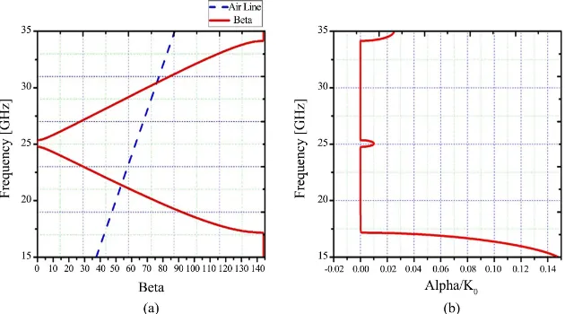
[image:4.595.210.538.188.318.2]The results of dispersion diagram for a unit cell are shown in Figure 4; Figure 4(a) shows the real part of complex propagation constant (β), while Figure 4(b) shows the imaginary part of complex propagation constant (the attenuation constant α) normalized to the free space propagation constant k0.
Figure 1. The intrinsic equivalent circuit model of the CSRR.
[image:4.595.239.518.340.717.2]Figure 2. The unit cell structure.
DOI: 10.4236/ojapr.2019.71001 5 Open Journal of Antennas and Propagation Figure 4. The results of dispersion diagram for unit-cell, (a) β/K0 and (b) α/K0.
3. Complete Antenna Design
The proposed antenna is designed based on substrate integrated wave guide (SIW) consisting of two horizontal metal plates, the ground plane and the transmission line plate with etching CSRR, printed on dielectric substrate. The two metal plates are connected together by using metal vias in both sides of the substrate. These vias act as side walls of the wave guide as shown in Figure 5.
The designed leaky wave antenna consists of ten unit-cells. The separation between the adjacent unit-cells is 0.2 mm. The overall antenna size is 6.6 × 41.4 mm2, which is printed on grounded Roger/RT Duroid 5880 (tm) substrate. To
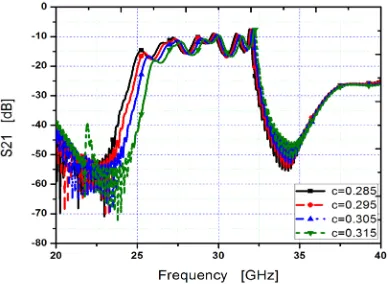
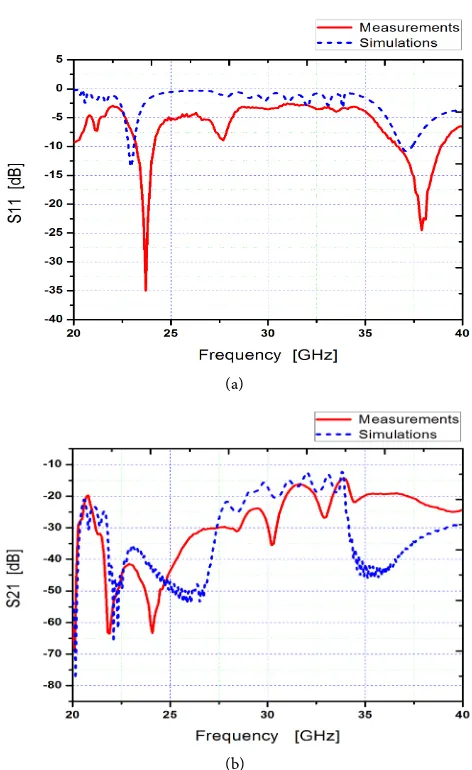
match the designed antenna to 50 Ω feed line, the two ends of the designed an-tenna are terminated by tapering matching sections. Figure 6 shows a paramet-ric study of outer radius of the CSRRb. The outer radius of 1.7 mm is the opti-mum one for the required application around 28 GHz. In Figure 7, a parametric study of the ring width c is introduced and 0.285 mm is chosen to be the ac-cepted one. The gap between the two rings is assumed to be equal the ring width. Figure 8 shows the fabricated antenna and its measurements. Figure 9 shows a comparison between the simulated and measure S parameters of the designed leaky wave antennas. Good agreements between the two results are obtained. These reflection and transmission coefficients are used to determine the nor-malized radiated power as follows:
2 2 11 21 1
rad in
P P = − S − S (3)
Figure 10 shows a comparison between the simulated and measured norma-lized radiated power as a function of the operating frequency. It can be noted that the maximum radiated power occurs at around 28 GHz, which it is expected from the results of complex propagation constant.
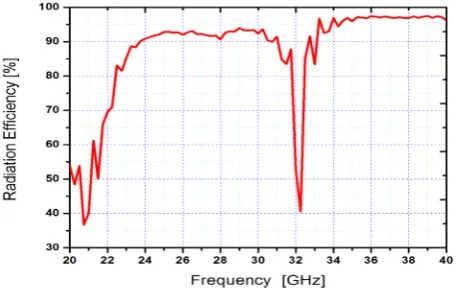
DOI: 10.4236/ojapr.2019.71001 6 Open Journal of Antennas and Propagation The radiation efficiency of this antenna is shown in Figure 13 which gives good efficiency.
[image:6.595.276.472.262.404.2]Figure 5. Leaky wave antenna of a SIW loaded by periodic CSRR.
Figure 6. Parametric study of outer radius of the CSRR.
Figure 7. Parametric study of the ring width.
[image:6.595.277.472.439.581.2] [image:6.595.269.479.614.703.2]DOI: 10.4236/ojapr.2019.71001 7 Open Journal of Antennas and Propagation (a)
[image:7.595.255.491.62.447.2](b)
Figure 9. (a) Comparison between the simulated and measured S11 of the designed leaky wave antenna; (b) Comparison between the simulated and measured S21 of the designed leaky wave.
[image:7.595.258.489.505.689.2]DOI: 10.4236/ojapr.2019.71001 8 Open Journal of Antennas and Propagation Figure 11. Radiationpattern at frequency 28 GHz.
Figure 12. Frequency scanning radiation pattern.
Figure 13. The radiation efficiency of the CSRR leaky wave antenna.
4. Conclusion
[image:8.595.260.489.496.640.2]ob-DOI: 10.4236/ojapr.2019.71001 9 Open Journal of Antennas and Propagation tained antenna can be used in the frequency range from 21 to 33 GHz. Frequen-cy scanning is also obtained. This property makes the proposed antenna be suit-able for scanning radar application, in addition to the proposed application of 5G communication. Tapering sections are used to terminate the two ends of the proposed antenna to be matched with the feeding network. Good matching is obtained by using this technique. The impedance matching, radiation pattern and radiation efficiency are studied for this antenna.
Conflicts of Interest
The authors declare no conflicts of interest regarding the publication of this paper.
References
[1] Garg, R. (2001) Microstrip Antenna Design Handbook. Artech House, Norwood. [2] Volakis, J. (2009) Antenna Engineering Handbook. McGraw-Hill, New York. [3] Xu, F. and Wu, K. (2013) Understanding Leaky-Wave Structures: A Special Form of
Guided-Wave Structure. IEEE Microwave Magazine, 14, 87-96.
[4] Goldstone, L. and Oliner, A.A. (1959) Leaky-Wave Antennas I: Rectangular Wave-guides. IRE Transactions on Antennas and Propagation, 7, 307-319.
https://doi.org/10.1109/TAP.1959.1144702
[5] Shokry, M.A. and Allam, A.M. (2017) Design of Uniform SIW Leaky Wave Anten-na: With and without Supported Ground. Loughborough Antennas & Propagation Conference, Loughborough, 14-15 November 2016, 1-5.
https://doi.org/10.1109/LAPC.2016.7807473
[6] Xu, F. and Zhang, X. (2010) Periodic Leaky-Wave Antenna for Millimeter Wave Applications Based on Substrate Integrated Waveguide. IEEE Transactions on An-tennas and Propagation, 58, 340-347.https://doi.org/10.1109/TAP.2009.2026593
[7] Gentile, G., Jovanović, V., Pelk, M.J., Jiang, L., Dekker, R., de Graaf, P., Rejaei, B., et al. (2013) Silicon-Filled Rectangular Waveguides and Frequency Scanning Antennas for mm-Wave Integrated Systems. IEEE Transactions on Antennas and Propaga-tion, 61, 5893-5901.https://doi.org/10.1109/TAP.2013.2281518
[8] Mondal, P. and Wu, K. (2016) A Leaky-Wave Antenna Using Periodic Dielectric Perforation for Millimeter-Wave Applications. IEEE Transactions on Antennas and Propagation, 64, 5492-5495.https://doi.org/10.1109/TAP.2016.2621032
[9] Shaw, R. and Mandal, M.K. (2016) SIW Periodic Leaky Wave Antenna with Im-proved H-Plane Radiation Pattern Using Baffles. IEEE Indian Antenna Week, Ma-durai, 6-10 June 2016, 59-62.https://doi.org/10.1109/IndianAW.2016.7883598
[10] Hayashi, Y., Sakakibara, K., Nanjo, M., Sugawa, S., Kikuma, N. and Hirayama, H. (2011) Millimeter-Wave Microstrip Comb-Line Antenna Using Reflection-Canceling Slit Structure. IEEE Transactions on Antennas and Propagation, 59, 398-406.
https://doi.org/10.1109/TAP.2010.2096180
[11] Mohammad-Ali-Nezhad, S. and Mallahzadeh, A. (2015) Periodic Ridged Leaky-Wave Antenna Design Based on SIW Technology. IEEE Antennas and Wireless Propaga-tion Letters, 14, 354-357.https://doi.org/10.1109/LAWP.2014.2361175
DOI: 10.4236/ojapr.2019.71001 10 Open Journal of Antennas and Propagation Components Letters, 15, 536-538.https://doi.org/10.1109/LMWC.2005.852801
[13] Javanbakht, N., Syrett, B. and Amaya, R. (2018) Leaky-Wave Antenna Based on Modified Aperture Half-Mode Substrate Integrated Waveguide. IEEE International Symposium on Antennas and Propagation & USNC/URSI National Radio Science Meeting, 14-21 July 2018, 1831-1832.
https://doi.org/10.1109/APUSNCURSINRSM.2018.8608880
[14] Huang, S.-T. and Tseng, C.-H. (2017) Hand-Gesture Sensing Doppler Radar with Metamaterial-Based Leaky-Wave Antennas. IEEE MTT-S International Conference on Microwaves for Intelligent Mobility, Nagoya, 19-21 March 2017, 49-52.
https://doi.org/10.1109/ICMIM.2017.7918853
[15] Gupta, S., Caloz, C. and Abielmona, S. (2008) CRLH Leaky-Wave Real-Time Spec-trum Analyzer (RTSA) with Unrestricted Time-Frequency Resolution. IEEE MTT-S International Microwave Symposium Digest, Atlanta, 15-20 June 2008, 807-810.
https://doi.org/10.1109/MWSYM.2008.4632955
[16] Mak, K.-M., So, K.-K., Lai, H.-W. and Luk, K.-M. (2017) A Magnetoelectric Dipole Leaky-Wave Antenna for Millimeter-Wave Application. IEEE Transactions on An-tennas and Propagation, 65, 6395-6402.https://doi.org/10.1109/TAP.2017.2722868
[17] Martinez-Ros, A.J., Gomez-Tornero, J.L. and Goussetis, G. (2013) Holographic Pattern Synthesis with Modulated Substrate Integrated Waveguide Line-Source Leaky-Wave Antennas. IEEE Transactions on Antennas and Propagation, 61, 3466-3474.
https://doi.org/10.1109/TAP.2013.2257650
[18] Eleftheriades, G.V., Iyer, A.K. and Kremer, P.C. (2002) Planar Negative Refractive Index Media Using Periodically L-C Loaded Transmission Lines. IEEE Transactions on Microwave Theory and Techniques, 50, 2702-2712.
https://doi.org/10.1109/TMTT.2002.805197
[19] Lin, I.H., Caloz, C. and Itoh, T. (2002) Transmission Characteristics of Left Handed Non Uniform Transmission Lines. Proceedings of Asia-Pacific Microwave Confe-rence, Kyoto, 19-22 November 2002, Vol. 3, 1501-1504.
[20] Caloz, C., Okabe, H., Iwai, H. and Itoh, T. (2002) Transmission Line Approach of Left-Handed Metamaterials. Proceedings of USNC/URSI National Radio Science Meeting, San Antonio, June 2002, 39.
[21] Oliner, A.A. (2002) A Periodic-Structure Negative-Refractive Index Medium with-out Resonant Elements. Proceedings of USNC/URSI National Radio Science Meet-ing, San Antonio, June 2002, 41.
[22] Siddiqui, O.F., Mojahedi, M. and Eleftheriades, G.V. (2003) Periodically Loaded Transmission Line with Effective Negative Refractive Index and Negative Group Velocity. IEEE Transactions on Antennas and Propagation, 51, 2619-2625.
https://doi.org/10.1109/TAP.2003.817556
[23] Eleftheriades, G.V., Siddiqui, O. and Iyer, A. (2003) Transmission Line Models for Negative Refractive Index Media and Associated Implementations without Excess Resonators. IEEE Microwave and Wireless Components Letters, 13, 53-55.
https://doi.org/10.1109/LMWC.2003.808719
[24] Baena, J.D., Bonache, J., Martın, F., Marques, R., Falcone, F., Lopetegi, T., Laso, M.A.G., Garcıa, J., Gil, I. and Sorolla, M. (2005) Equivalent Circuit Models for Split Ring Resonators and Complementary Split Rings Resonators Coupled to Planar Transmission Lines. IEEE Transactions on Microwave Theory and Techniques, 53, 1451-1461.https://doi.org/10.1109/TMTT.2005.845211
DOI: 10.4236/ojapr.2019.71001 11 Open Journal of Antennas and Propagation
[26] Caloz, C. and Itoh, T. (2006) Electromagnetic Metamaterials: Transmission Line Theory and Microwave Applications. Chapter 6, John Wiley & Sons Inc., Hoboken. [27] Lai, A., Itoh, T. and Caloz, C. (2004) Composite Right/Left-Handed Transmission
Line Metamaterials. IEEE Microwave Magazine, 5, 34-50.