Abstract— This paper presents a simple and effective adaptive PDPID with ILC control scheme. The adaptive control scheme is for tuning PD control gains for two-link flexible manipulator and the ILC is to improve the overall system performance. The manipulator is modelled using Lagrange and assume mode method. The adaptive control scheme continuously tunes PD controller gains depending on the error value without switching. The proposed control law is tested in Matlab/Simulink simulation environment and its performance is compared with PDPID, PDPIDILC and adaptive PDPID controllers. The effect of constant disturbance, sine wave disturbance and white noise disturbances on the proposed controller is extensively studied. The results show the effectiveness and robustness of the proposed adaptive PDPID controller with iterative learning.
Index Terms— PID control, flexible manipulator, Iterative learning control, Adaptive control.
I. INTRODUCTION
lexible manipulator systems (FMSs) offer several advantages compared to their rigid counterparts which include: faster manipulation, energy efficient, higher payload to weight ratio, and less overall cost [1-4]. Despite these advantages, control of FMSs is very challenging because of its distributed parameter nature. [5]. Proportional-integral-derivative (PID) controller constitutes over 90% of controllers used in industry today [6]. This is because PID controllers are cheap, robust over a wide range of operating condition, simple in structure and easy to implement [7]. Lots of PID based control schemes have been reported in the literature [8- 12]. Performance of fixed-gain PID controllers is limited in real time operations. With fixed-gain controller, steady state error will continue to be present, though high gain can reduce this error but can’t eliminate it due to the effect of unmoldelled dynamics in high order deformation modes [13] and also there is a limit to which gains can be increased due to actuator limit. A number of adaptive approaches have been proposed in literature [14-20] to take care of shortcomings of the fixed-gain PID controllers. The major drawback of these adaptive approaches is that it requires high computational load [21].
Iterative learning control (ILC) is a feedforward control technique to improve performance of a system doing repetitive tasks by reducing tracking error from trial to trial [22]. Advantages of ILC include: good transient performance, [23]. ILC scheme estimate a compensation input for the next iteration in order to reduce the error in the
Manuscript received November 11, 2011; revised February 4, 2012. R. M. Mahamood is with Department of Mechanical Engineering, University of Ilorin, Nigeria. (Tel: +2348033744353; e-mail:
next trial and converges to minimize tracking error. ILC strategy like any other open-loop/feedforward control technique requires accurate knowledge of the plant for its effective use [24]. A properly designed feedforward controller has been proved to reduce complexity of feedback controller [25]. The feedback controller will ensure system stability [26] while the ILC will improve system performance.
Adaptive Iterative learning control schemes have also been reported in the literature [27-29], in these control algorithms adaptation is made on the ILC algorithm and the computational load is higher than the control scheme proposed in this study.
Combining adaptive scheme with ILC is based on adapting the ILC scheme in the literature. In this study a different approach is used by designing an adaptive control scheme for automatic tuning of the PD gains while the ILC control algorithm is used to improve the overall performance of the system. Simple and efficient adaptive and ILC algorithm were developed in this study with less computational load. A set-point regulation problem of two-link flexible manipulator performing a repetitive task is considered with constant disturbance, sine wave disturbance and white noise disturbance. The dynamic model of the system is developed using Lagrange and Assume mode method. The model has been developed by [30]. Performance of the proposed controller is studied through simulation in Matlab/Simulink environment. The performance is compared with PDPID, PDPIDILC and adaptive PDPID controllers. The results are presented and discussed in detail.
The rest of the paper is organised as follows: the system dynamics is presented in section 2. Section 3. gives the controllers’ design schemes while, section 4 gives the simulation results and discussion and finally the conclusion is presented in section 5.
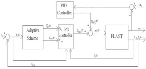
[image:1.595.331.539.633.752.2]II. MATHEMATICALMODELLING
Fig 1. Planar two-link flexible manipulator
Adaptive PDPID with Iterative Learning for
Two-link Flexible Manipulator
Rasheedat. M. Mahamood
The mathematical model of the planar two-link flexible manipulator shown in Fig. 1. has been developed by [30] using Lagrange and Assumed mode method. The links are modelled as Euler-Bernoulli beam with proper clamped-mass boundary conditions. Small elastic deflection is assumed and it is restricted to the plane of rigid motion.
X
ˆ
0,
Y
ˆ
0
,
X
i,
Y
i
,
X
ˆ
i,
Y
ˆ
i
are the inertial frame, the rigid body moving frame, and the flexible body moving frame associated to link i respectively.
iis the rigid body motion (joint angle), andy
i
x
i is the transversal deflection of link i (0
x
i
i), where
i is the length of link i. The closed form equation:i
q
q
q
q
q
)
h
(
,
)
K
(
B
(1)where i n n n nn T
ei ei
t
q
(
)
(
1...
11...
1,...
,1...
,)
, is a N-vector generalised coordinates (N
n
in
ei), τ is n-vector of generalized torques applied at the joints of n-link. B is a positive-definite symmetric inertia matrix, h is a vector of Coriolis and centripetal forces, and K is the diagonal stiffness matrix. Detailed derivation of the mathematical model can be found in [30]III. CONTROLLERDESIGN
The control schemes involve four stages. The first stage is the hybrid PD-PID controller design for the two-link flexible manipulator. In the second stage, the hybrid PD-PID controller is extended to incorporate the ILC scheme. The third stage involves removing the ILC and replacing it with adaptive control scheme. This is done to be able to compare each of these control algorithms. Finally both ILC and adaptive control schemes are then incorporated in to the hybrid PDPID.
A. Hybrid PD-PID Controller Design.
[image:2.595.308.552.119.277.2]The control objective is to design PD controllers for each of the links in Fig 1. so that the hub angles follow the desired trajectories. Also PID controllers are used for vibrations control through end-point acceleration feedback [31]. The hybrid PD-PID control architecture is shown in Fig. 2. For the PD controller, the control input is given by:
dt
d
K
t
t
K
A
t
u
i vi i id Pi ciPDi
(
)
(
))
(
)
(
i=1,2 (2)Where uPDi is PD control input, θid, θi, Aci, KPi and Kvi are
the desired hub angle, actual hub angle, amplifier, proportional and derivative gains respectively.
PID controller uses end-point elastic acceleration for vibration suppression of each of the links because of the coupling effects. The control input is as follows:
dt
de
k
dt
t
e
k
t
e
k
t
u
PID pj ij djj
(
)
(
)
(
)
j= 1, (3))
(
)
(
)
(
t
t
t
e
(4)Where uPIDi is the PID control input, Kpj, KIj, and kdj are
the proportional, integral and derivative gains. αid (t) and αi
(t) are desired and actual end-point acceleration. αid (t) is
equal to zero since the objective is to have zero acceleration. Total control input τi (t) to the system is given by:
)
(
)
(
)
(
t
u
t
u
t
i
i PID
PD
i
i=1, 2 (5)Fig. 2. PD-PID Control architecture [31]. B. Iterative Learning Control Scheme
[image:2.595.305.553.381.455.2]ILC is used to improve the performance of the hybrid PD-PID controller in 3.1 above. The hybrid PDPID control scheme is extended to include ILC. The structure of the control law is shown in Fig.3 according to [ 32].
Fig. 3. PDPIDILC Control architecture [32]
The structure of the learning scheme is shown in Fig. 4. and is given by:
)
(
))
(
)
(
(
)
(
2 ) 1 ( ) 1 (t
e
t
t
t
u
ik i k i ik i k i
i=1,2 (6)
Where ui (k+1) and τik are the next iterative and present total
control inputs respectively, Гi is the learning filter, and ψi is
[image:2.595.49.232.585.634.2]the Proportional learning gain.
Fig. 4. Structure of the ILC learning algorithm [32]. C. Adaptive PDPID Control Scheme
Figure 5. shows the adaptive PDPID control structure. The adaptive control scheme is given by:
1
)]
(
)
(
[
)
(
2
t
t
t
i id ii
[image:2.595.308.550.619.673.2]Where λi(t) is the adaptive parameter that constantly adjusts
[image:3.595.49.295.91.208.2]the PD controller gains, and Φi is the adaptive weight gain.
Fig.5. Structure of the proposed adaptive PDPID control. D. Adaptive PDPID with ILC Control Scheme
The proposed control architecture is shown in Fig. 5. achieved by extending controller in section C. to incorporate ILC in Fig.4. The total control input is given by:
)
(
]
[
)]
(
))
(
)
(
(
[
)
)
(
)
(
)(
(
)
(
( 1)t
e
k
k
k
t
k
t
t
k
u
t
t
t
t
u
i Di Ii Pi i vi i id pi k i i id i i
[image:3.595.295.523.229.319.2]
i=1, 2 (8) [image:3.595.48.291.295.458.2]Fig. 6. Adaptive PDPILILC control architecture IV. SIMULATIONRESULTS To demonstrate the efficiency of the proposed control scheme, test was carried out through simulation within Matlab/Simulink environment. The robustness of the proposed controller is also tested with constant disturbance and white noise disturbance both are applied to link one and sine wave disturbances applied to both links and the results are presented. The parameter of the two-link flexible manipulator is given in Table 1. according to [30].
Table 1. Two-link flexible manipulator parameters [30]
Symbol Parameter Value
Ρ1= ρ2 Mass density 0.2 kgm-3
EI1 = EI2 Flexural rigidity 1.0 Nm2
L1 =l1 Length 0.5m
Jh1 =Jh2 Mass moment of inertia of
the hub
0.1 kgm2
G Gear ratio 1
M1 =m1 Mass of the link 0.1kg
Mp Mass of pay load 0.1kg
Jo1 =Jo2 Mass moment of inertia of
the link about its hub 0.0083 kgm
2
Jp Mass moment of inertia of
the end effector 0.0005 kgm
2
The manipulator is expected to track a unit step input, the hub angle, end-point acceleration and the controlled toques are presented in Figs. 7to 10. PD and PID controller gains are given in Table 2 and the adaptive weight and the ILC gains are presented in Tables 3 and 4 respectively. The PD and PID gains of the feedback controller gain are tuned simultaneously and manually because using the available tuning methods on a highly non-linear open-loop unstable system like the two-link flexible manipulator gives an unsatisfactory result [33] and is very slow [34].The ILC gains are also tuned systematically because there is no available method of tuning the ILC gains [35]. The adaptive weight was tuned systematically to achieve good results. Table 2. PDPID Controller gains
Ac PD gains PID gains Kp Kv Kp KI Kd
Link1 1 1.1 1.1 0.2 0.001 1.5 Link 2 1 0.2
5 0.42 0.1 0.1 0.5
[image:3.595.304.542.527.601.2]The system was exited with a unit step input, the responses obtained using adaptive PDPID with ILC controller are compared with PDPID, PDPIDILC, and adaptive PDPID controllers and are shown in Fig. 7. It was observed that there is an improvement in performance of PDPIDILC compared to PDPID with little overshoots. A smoother tracking is achieved with adaptive PDPID and adaptive PDPIDILC with the latter having an improved performance compared with the former. The hub angle tracking is faster with the proposed controller (Fig. 7a) compared to adaptive PDPID. The proposed controller has the least steady state error (Fig 7b). The proposed controller has the least amplitude of vibration compared to the other three and it settles down quickly (Fig. 7c). Figure 7d shows the control torque which is smoother for the proposed controller and also lower than the other three control torques.
Table 4: adaptive weight Φ
Link 1 17.5 Link 2 1.42
4.1 Effect of constant Disturbance.
To further demonstrate the effectiveness of the proposed controller, constant disturbance was introduced at the first joint and the results are shown in Fig.8. It is observed that the constant disturbance degraded the PDPID and PDPIDILC controllers while there is no significant change in the performances of the proposed controller and adaptive PDPID controller as shown in Fig. 8a. The proposed controller still maintained its improvement over the adaptive PDPID controller, this shows the robustness of the proposed controller to a constant disturbance. Figures 8b to 8d show similar results as observed in Fig. 7b to 7d for the proposed controller. The proposed controller achieves the required performance with no significant change in its steady state
Table 3: ILC gains
Ψ [image:3.595.47.289.609.770.2]error, end-point acceleration and input torque. The PDPID and PDPIDILC have very large steady state errors.
4.2 Effect of Sine wave Disturbance.
Sine wave disturbances are applied to both joints and the effect are shown in Fig. 9. Figure 9a shows an unstable tracking performance of PDPID and PDPIDILC controllers compared with an insignificant change in the behaviour of the adaptive PDPID and the proposed controller. With the proposed controller having overall best tracking performance. Figures 9b to 9d also show that the proposed controller is robust to the disturbances.
4.3 Effect of White Noise Disturbance.
To further demonstrate the robustness of the proposed controller a white noise signal was introduced at the first joint and the results are shown in Fig. 10. It was observed that the white noise destabilises the PDPID and PDPIDILC controllers while there are no significant changes in the performance of the adaptive PDPID controller and proposed controller (Fig. 10a). Similar results are observed in Fig. 10b to 10d of large steady state error (Fig. 10b), unstable behaviour in acceleration and applied torque (Fig 10c and 10d respectively) with PDPID and PDPIDILC controllers. Though adaptive PDPID and the proposed controller show no significant changes in their behaviours but the proposed controller still maintain its overall best performance. This shows the robustness of the proposed controller to an irregular disturbance like white noise.
V. CONCLUSSION
Adaptive PDPID with ILC control algorithm has been developed for two-link flexible manipulator. The proposed controller has been compared with hybrid PDPID, PDPILILC and adaptive PDPID controllers. A very simple adaptation law to constantly tune the PD gains was developed. The feedforward ILC learning algorithm incorporated in the adaptive PDPID controller uses the square of the previous hub angle tracking error and total control input to improve the tracking performance of the system. The ILC scheme estimates the required control inputs compensation for each iteration such that the overall error is reduced and converges to minimize tracking error. The proposed controller was tested and compared to PDPID, PDPIDILC and adaptive PDPID through simulation in Matlab/Simulink environment. Effect of constant disturbance, sine wave disturbance and white noise disturbance were extensively studied on the proposed controller and compared with PDPID, PDPIDILC and adaptive PDPID to show its effectiveness and robustness. The results were presented and discussed. The results show that an impressive performance is achieved with the proposed adaptive PDPID with ILC controller compared to the other three controllers. Also the proposed controller is robust to constant, sine wave and noisy disturbances.
REFERENCES
[1] Azad, A. K. M. Analysis and design of control mechanisms for flexible
manipulator systems, PhD thesis, Department of Automatic Control and
Systems Engineering, The University of Sheffield, UK (1994).
[2] Poerwanto, H. Dynamic Simulation and Control of flexible manipulator
systems, PhD thesis, Department of Automatic Control and Systems
Engineering, The University of Sheffield, UK (1998).
[3] Sutton, R. P., Halikias, G. D., Plummer A. R. and Wilson, D. A. Modelling and H∞ control of a single-link flexible manipulator, Proc. of
the Instn Mech Engrs, vol. 213 Part 1, (1999), pp. 85-104.
[4] Yim, J. G., Yeon, J. S., Lee, J., Park, J. H., Lee, S. H. and Hur, J. S. Robust control of flexible robot manipulators, Proceedings of the
SICE-ICASE International Joint Conference, 2006, pp. 3963 – 3968.
[5] Dwivedy, S.K. and Eberhard, P. Dynamic analysis of flexible manipulators, a literature review, Mechanism and Machine Theory,
(2006), vol. 41, no. 7, pp. 749-777.
[6] Ho, M. T. and Tu, Y. W. PID controller design for a flexible link manipulator, Proceedings of the 44th IEEE Conference on Decision and
Control and European Control Conf.,, 2005, pp. 6841 – 6846.
[7] Ang, K. H., Chong, G. and Li, Y. PID control system analysis, design, and technology, IEEE Transactions on Control Systems Technology,
Vol. 13, No. 4, 2005, pp. 559 – 576.
[8] Zain, B.A. Md. and Tokhi M. O. and S. F. Toha, PID-based control of a single-link flexible manipulator in vertical motion with genetic optimisation, Proceedings of the Third UKSim European Symposium on
Computer Modeling and Simulation (EMS’09), 2009, pp. 355 – 360.
[9] Ahmad, M. A. Vibration and input tracking control of flexible manipulator using LQR with non-collocated PID controller, Proceedings of the Second UKSim European Symposium on Computer Modeling and
Simulation (EMS’08), 2008, pp. 40 – 45.
[10] He, S. Z., Tan, S. H., Xu F. L. and Wang, P. Z. PID self-tuning control using a fuzzy adaptive mechanism, Proceedings of the Second IEEE
International Conference on Fuzzy Systems, 1993, vol. 2, pp. 708–713.
[11] Sasaki, M., Asai, A., Shimizu, T. and Ito, S. Self-tuning control of a two-link flexible manipulator using neural networks, Proceedings of the
ICROS-SICE International Joint Conference, 2009, pp. 2468 – 2473.
[12] Ahmad, M. A., Suid, M. H., Ramli, M. S., Zawawi M. A. and Ismail, R. M. T. R. PD fuzzy logic with non- collocated PID approach for vibration control of flexible joint manipulator, Proceedings of the 6th
International Colloquium on Signal Processing and Its Applications
(CSPA), 2010, pp. 1 – 5.
[13] De Luca, A. and Panzieri, S. An iterative scheme for learning gravity compensation in flexible robot arms, Automatica, 1994, vol. 30(6), pp.993-1002.
[14] Onen U., Kalyoncu M., Tinkir M., and Botsali F. M. Adaptive network based fuzzy logic control of a rigid – flexible robot manipulator, International Conference on Computer and Automation
Engineering (ICCAE), vol. 1, 2010, pp102-106.
[15] Ahmad M. A., Ismail R.M.T.J. and Ramli M. S., “Optimal Control with Input Shaping for Input Tracking and Vibration Suppression of a
Flexible Joint manipulator”, European Journal of Scientific Research,
2009, Vol. 28(4), pp.583-599.
[16] Becedas, J., Trapero, J. R., Feliu, V., and Sira-Ramírez, H. Adaptive controller for single-link flexible manipulators based on algebraic identification and generalized proportional integral control, IEEE Transactions On Systems, Man, And Cybernetics—Part B: Cybernetics,
vol. 39, no. 3, June 2009, pp. 735-751.
[17] Maouche, A.R. and Attari, M. CMAC based adaptive control of a flexible link manipulator, 35th Annual Conference of IEEE on
Industrial Electronics, IECON '09, 2009, pp1480-1485.
[18] Dogan, M., Istefanopulos, Y., and Diktas, E.D. Nonlinear control of two-link flexible arm with adaptive internal model,
Proceedings of the IEEE International Conference on Mechatronics,
2004, pp. 292-298.
[19] Tinkir, M., Onen, U., Kalyoncu, M., and Sahin, Y. Adaptive network based interval type-2 fuzzy logic controller design for a single flexible link carrying a pendulum, The 2nd International Conference on
Computer and Automation Engineering (ICCAE), 2010, pp. 112-116.
[20] Kar, I., and Behera, L. Direct adaptive neural control for affine nonlinear systems, Applied Soft Computing vol. 9, 2009, pp. 756–764 [21] Kuc, T. –Y., Nam, K. and Lee, J. S., An iterative learning control of
robot manipulator, IEEE Transaction on Robotic and Automation, 1991, vol.7 (6), pp. 835-842. [33] Tokhi, M. O. and Azad, A. K. M. Flexible
Robot Manipulators -Modelling, Simulation and Control, Institution of
Engineering and Technology, London, 2008.
[34] Eriksson, E. and Wikander, J. Robust PID design of flexible manipulators through pole assignment, Proc. of the 7th International
Workshop on Advanced Motion Control, 2002, pp. 420 – 425.
(7a)
(7b)
(7c)
[image:5.595.63.271.57.727.2](7d)
Fig.7: Time history of hub angle, tracking error, end-point acceleration and applied torque with step input.
(8a)
(8b)
(8c)
(8d)
[image:5.595.318.524.57.720.2](9a)
(9b)
(9c)
[image:6.595.62.271.38.701.2](9d)
Fig. 9: Time history of hub angle, tracking error, end-point acceleration and applied torque with sine wave disturbance.
(10a)
(10b)
(10c)
[image:6.595.322.525.50.708.2](10d)
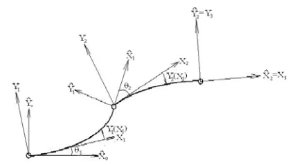
![Fig. 2. PD-PID Control architecture [31].](https://thumb-us.123doks.com/thumbv2/123dok_us/1282357.656816/2.595.308.552.119.277/fig-pd-pid-control-architecture.webp)