University of Warwick institutional repository:
http://go.warwick.ac.uk/wrap
A Thesis Submitted for the Degree of PhD at the University of Warwick
http://go.warwick.ac.uk/wrap/77722
This thesis is made available online and is protected by original copyright.
Please scroll down to view the document itself.
Modelling, Real-Time Simulation and Control of
Automotive Windscreen Wiper Systems for Electronic
Control Unit Development
by
Mark Dooner
A thesis submitted in partial fulfilment of the requirements
for the degree of
Doctor of Philosophy in Engineering
The University of Warwick
School of Engineering
i
Table of Contents
List of Figures ... vii
List of Tables ... xiii
Acknowledgements ...xiv
Declarations ... xv
Abstract ...xvi
List of Abbreviations ... xvii
Chapter 1 - Introduction ... 1
1.1 Background ... 1
1.2 Objectives ... 5
1.3 Structure ... 6
1.4 Publications ... 8
Chapter 2 - Literature Review... 9
2.1 Introduction ... 9
2.2 Automotive Product Development: HIL and Model Based Design ... 9
2.3 Current Wiper System Models and Research ... 12
2.3.1 Vibration Analysis and Mitigation Research ... 12
2.3.2 Control of Wiper Systems ... 15
2.3.3 Dynamic Models of Wiper Systems ... 16
2.4 Parameter Identification ... 18
2.4.1 Off-line Parameter Identification using Genetic Algorithms ... 18
ii
2.5 Friction in a Wiper System ... 19
2.6 Vehicle and Wiper Aerodynamics ... 23
2.7 Adaptive Control Using Single Neuron PID Controllers ... 25
Chapter 3 - Wiper Motor Modelling ... 27
3.1 Introduction ... 27
3.2 Wiper Motor Structure ... 28
3.3 Model Derivation of the Wiper Driving DC Motor ... 31
3.3.1 Torque Production ... 32
3.3.2 Back EMF ... 37
3.3.3 Resistance and Inductance ... 41
3.4 Dynamic Equations ... 42
3.5 Simulation Models ... 43
3.5.1 State Space Model ... 43
3.5.2 Physical Model ... 45
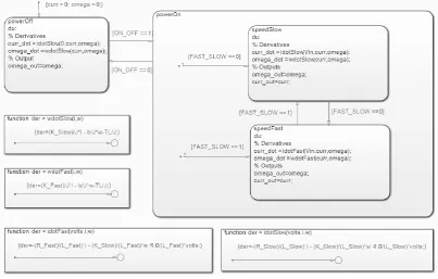
3.5.3 Stateflow Model ... 47
3.6 Wiper Motor Park Switch Strategies ... 48
3.6.1 Mechanical Park Switch ... 49
3.6.2 Depressed Mechanical Park Switch ... 52
3.7 Discussion ... 56
Chapter 4 - Multibody Dynamics Mechanical Modelling ... 57
4.1 Introduction ... 57
iii
4.2 Planar Kinematics Model based on Computational Dynamics ... 59
4.2.1 Slave Driven Linkage System ... 59
4.2.2 Wiper Arms ... 71
4.2.3 Wiper Blade ... 74
4.2.4 Planar Kinematic Simulation... 75
4.3 Physical Model Based on SimMechanics ... 77
4.3.1 Slave Driven Linkage System ... 77
4.3.2 Wiper Arms ... 81
4.3.3 Wiper Blade ... 82
4.3.4 Gravity Vector ... 83
4.4 Wiper Blade Friction Force ... 84
4.4.1 Dry Friction ... 85
4.4.2 Wet Friction ... 88
4.5 Aerodynamic Lift and Drag Forces ... 91
4.6 Whole System Simulation... 94
4.7 Discussion ... 96
Chapter 5 - Parameter Identification and Model Validation ... 98
5.1 Introduction ... 98
5.2 Identification Methodology ... 99
5.3 Wiper Motor Transfer Function Identification ... 103
5.4 Wiper Motor Parameter Measurement ... 111
iv
5.4.2 EMF and Torque Constants ... 111
5.4.3 Armature Inductance... 112
5.4.4 Motor Inertia ... 113
5.4.5 Refining Measurements and Damping Coefficient Estimation ... 113
5.5 Genetic Algorithm Identification of System Parameters ... 116
5.5.1 Genetic Algorithm Theory ... 116
5.5.2 Cost Function ... 118
5.5.3 Defining GA Parameters ... 119
5.5.4 Generating the Initial Population ... 120
5.5.5 Selecting Mates using Tournament Selection ... 120
5.5.6 Carry out Mates Using Random Blending ... 121
5.5.7 Mutations ... 122
5.5.8 Recalculate Costs ... 122
5.5.9 Results of Parameter Optimisation Using Genetic Algorithms ... 123
5.6 Local Optimiser Stage ... 126
5.7 Discussion ... 128
Chapter 6 - Model Simplification for HIL Implementation ... 130
6.1 Introduction ... 130
6.2 Kinematic Approximation Using Look-up Tables ... 132
6.3 No-Load Torque Polynomial Model... 132
6.4 Neural Network Modelling ... 136
v
6.4.2 Mechanical Load Modelling... 139
6.4.3 Whole Wiper System Modelling ... 145
6.4.4 Neural Network Limitations ... 153
6.5 Discussion ... 154
Chapter 7 - Adaptive Control of the Wiper System ... 156
7.1 Introduction ... 156
7.1.1 Classic Wiper Control Example ... 157
7.2 PID Velocity Control ... 158
7.3 Single Neuron Adaptive PID Control ... 161
7.3.1 Hebb Learning Rule ... 164
7.3.2 Error Only Hebb Learning Rule ... 164
7.3.3 Quadratic Learning Rule ... 165
7.3.4 Single Neuron Adaptive PID Control Results and Discussion ... 165
7.4 Single Neuron Fuzzy Adaptive PID Control ... 168
7.4.1 SNPID with Fuzzy Controller Results and Discussion ... 172
7.5 Sensorless Control Neural Network ... 174
7.6 Stateflow Control Implementation ... 177
7.7 Discussion ... 177
Chapter 8 - Generic Modelling and Real-Time Implementation ... 180
8.1 Introduction ... 180
8.2 Simulink Library ... 180
vi
8.3.1 Wiper Motor Panel ... 182
8.3.2 Wiper Linkages Panel ... 182
8.3.3 Wiper Arms Panel ... 184
8.3.4 Wiper Blade Panel ... 184
8.3.5 Environment Panel ... 184
8.3.6 Parameter Identification Panel ... 184
8.3.7 Generate Simulation Model Panel ... 184
8.4 dSPACE Real-Time Simulator Implementation ... 185
8.5 Discussion ... 192
Chapter 9 - Conclusions and Further Work ... 194
9.1 Conclusions ... 194
9.2 Suggested Further Work ... 197
References ... 200
Appendix A - Wiper Motor State Space Simulation Code ... 214
Appendix B - Slave Driven Linkage Parameters Code ... 216
Appendix C - Linkage System Kinematic Equations ... 217
Appendix D - Grashof’s Law for Slave Driven Linkages Matlab Code ... 223
Appendix E - Genetic Algorithm Matlab Code ... 224
vii
List of Figures
Figure 1-1: Global Passenger Car Sales... 1
Figure 1-2: V Model for Product Development ... 3
Figure 1-3: Body Electronics ECU HIL Simulation ... 4
Figure 1-4: Wiper System Block Diagram ... 5
Figure 3-1: Wiper Motor Construction ... 28
Figure 3-2: Wiper Motor Electrical Input Placement ... 29
Figure 3-3: Wiper Motor Commutator Connection ... 30
Figure 3-4: Wiper Motor Wiring Diagram ... 31
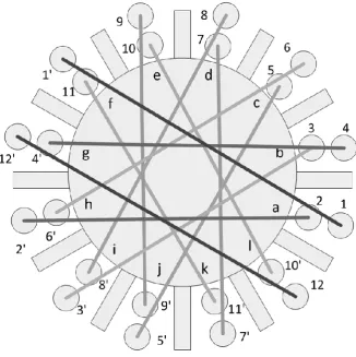
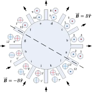
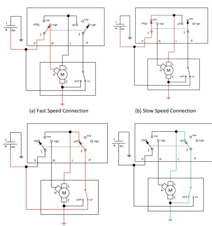
Figure 3-5: Wiper Motor Current Paths (Slow) ... 33
Figure 3-6: Wiper Motor Current Paths (Fast) ... 33
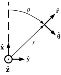
Figure 3-7: Cylindrical Coordinate System ... 34
Figure 3-8: Single Coil Flux Surface and Flux Surface Element ... 38
Figure 3-9: Wiper Motor Electrical Equivalent Circuit ... 42
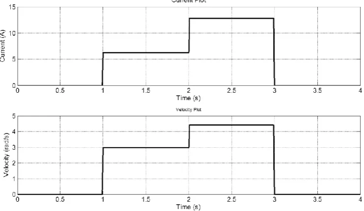
Figure 3-10: Motor State Space Model Simulation Results... 45
Figure 3-11: Wiper Motor Physical Model ... 46
Figure 3-12: Motor Physical Model Simulation Results ... 46
Figure 3-13: Wiper Motor Stateflow Implementation ... 47
Figure 3-14: Wipers in Park Position ... 49
Figure 3-15: Mechanical Park Switch Strategy ... 50
Figure 3-16: Mechanical Park Switch Strategy Simulation Model ... 51
Figure 3-17: Mechanical Park Switch Strategy Simulation Results ... 51
Figure 3-18: Mechanical Park Switch Switching Configuration ... 52
Figure 3-19: Depressed Mechanical Park Switch Strategy ... 53
Figure 3-20: Depressed Mechanical Park Switch Strategy Simulation Model ... 54
viii
Figure 3-22: Depressed Mechanical Park Switch Strategy Simulation Results ... 55
Figure 3-23: Depressed Mechanical Park Switch Switching Configuration ... 55
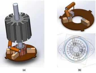
Figure 4-1: Solidworks Model of the Wiper System ... 57
Figure 4-2: Slave Driven Linkage System Diagram ... 59
Figure 4-3: Double Rocker Linkage Inequality Derivation (1) ... 69
Figure 4-4: Double Rocker Linkage Inequality Derivation (2) ... 70
Figure 4-5: Straight Wiper Arm ... 71
Figure 4-6: Bent Wiper Arm... 72
Figure 4-7: Wiper Blade ... 74
Figure 4-8: Planar Kinematics Simulation Flow Diagram ... 76
Figure 4-9: Planar Kinematics Simulation Plots ... 77
Figure 4-10: Linkage System Physical Model I/O ... 77
Figure 4-11: Linkage System Physical Model ... 78
Figure 4-12: Linkage System Physical Model Body Level Parameterisation ... 79
Figure 4-13: Linkage System Physical Model Body Orientation Parameterisation ... 80
Figure 4-14: Linkage System Physical Model Top Level Parameterisation ... 81
Figure 4-15: Straight Wiper Arm Physical Model I/O ... 81
Figure 4-16: Straight Wiper Arm Physical Model ... 82
Figure 4-17: Straight Wiper Physical Model Body Level Parameterisation ... 82
Figure 4-18: Wiper Blade Physical Model I/O ... 83
Figure 4-19: Wiper Blade Physical Model... 83
Figure 4-20: Friction Coefficient in Different Windscreen Conditions ... 85
Figure 4-21: Dry Friction Coefficient against Velocity (Literature) ... 86
Figure 4-22: Dry Coefficient of Friction Simulation ... 87
Figure 4-23: Dry Friction Coefficient Simulink Model ... 87
ix
Figure 4-25: Wet Friction Coefficient vs Force for Different Velocities (Literature) ... 89
Figure 4-26: Wet Coefficient of Friction Simulation ... 90
Figure 4-27: Wet Friction Coefficient Simulink Model ... 91
Figure 4-28: Drag and Lift Coefficients against Wiper Angle ... 92
Figure 4-29: Drag and Lift Force Simulation Model... 93
Figure 4-30: Aerodynamic Forces Simulation Results ... 93
Figure 4-31: Whole SimMechanics Model Example ... 94
Figure 4-32: SimMechanics Model Simulation Results ... 95
Figure 4-33: SimMechanics Model Simulation Plots ... 95
Figure 5-1: Simulation Model used for Identification ... 100
Figure 5-2: Park Switch Comparison Issue Example ... 101
Figure 5-3: Park Step Demonstration ... 101
Figure 5-4: Stateflow Sub Chart for Parameters Identification Data Generation ... 102
Figure 5-5: Parameter Identification and Model Validation Data Example ... 102
Figure 5-6: Parameter Identification Procedure ... 103
Figure 5-7: Motor Transfer Function Simulation Results ... 105
Figure 5-8: Transfer Function Parameters Identification Input Data (Slow Motor) ... 108
Figure 5-9: Transfer Function Parameters Identification Input Data (Fast Motor) ... 108
Figure 5-10: Transfer Function Parameters Identification Results (Slow)... 110
Figure 5-11: Transfer Function Parameters Identification Results (Fast) ... 110
Figure 5-12: Wiper Motor Parameter Identification Comparison Results ... 114
Figure 5-13: Wiper Motor Parameter Identification Residuals ... 115
Figure 5-14: Genetic Algorithm Flow Diagram and Schematic ... 117
Figure 5-15: Genetic Algorithm Cost Function Plot ... 124
Figure 5-16: Genetic Algorithm Results Comparison ... 125
x
Figure 5-18: Local Optimiser Results Comparison ... 127
Figure 5-19: Local Optimiser Residuals ... 127
Figure 6-1: Simulink Fixed Step Solver Comparison ... 131
Figure 6-2: No-Load Torque Approximation Performance ... 135
Figure 6-3: No-Load Torque Approximation GA Performance ... 135
Figure 6-4: General Feed Forward Neural Network Structure ... 136
Figure 6-5: Neural Network Supervised Training Block Diagram ... 138
Figure 6-6: NARX Model Diagram ... 139
Figure 6-7: Neural Network Performance against Number of Hidden Layers ... 141
Figure 6-8: Mechanical System Feed Forward NN Approximation Schematic ... 142
Figure 6-9: Mechanical System NN Dry Torque Performance (Training) ... 142
Figure 6-10: Mechanical System NN Wet Torque Performance (Training) ... 143
Figure 6-11: Mechanical System NN Dry Torque Performance (Validation) ... 143
Figure 6-12: Mechanical System NN Wet Torque Performance (Validation) ... 144
Figure 6-13: Hybrid Physical and Neural Network Model ... 145
Figure 6-14: Motor Neural Network NARX Approximation Schematic ... 146
Figure 6-15: Motor NARX Model Slow Mode Performance (Current) ... 147
Figure 6-16: Motor NARX Model Slow Mode Performance (Velocity) ... 148
Figure 6-17: Motor NARX Model Fast Mode Performance (Current) ... 148
Figure 6-18: Motor NARX Model Fast Mode Performance (Velocity) ... 149
Figure 6-19: Full Wiper System NN Implementation (Top Level) ... 150
Figure 6-20: Full Wiper System NN Implementation (Bottom Level) ... 151
Figure 6-21: Full Wiper System NN Simulink Results (Current and Position) ... 152
Figure 6-22: Full Wiper System NN Simulink Results (Torque and Velocity) ... 152
Figure 6-23: Neural Network Limitation Example ... 153
xi
Figure 7-2: PID Controller Block Diagram ... 159
Figure 7-3: PID Control Graphical Results ... 160
Figure 7-4: Single Neuron Model... 162
Figure 7-5: Single Neuron PID Control System Block Diagram ... 163
Figure 7-6: Single Neuron Hebb Learning Rule Results ... 166
Figure 7-7: Single Neuron Error-Hebb Learning Rule Results... 166
Figure 7-8: Single Neuron Quadratic Learning Rule Results ... 167
Figure 7-9: Fuzzy Membership Functions – Input ... 169
Figure 7-10: Fuzzy Membership Functions – Output ... 171
Figure 7-11: Single Neuron Fuzzy PID Control System Block Diagram ... 171
Figure 7-12: Single Neuron Hebb Learning Rule with Fuzzy Controller Results ... 172
Figure 7-13: Single Neuron Error-Hebb Learning Rule with Fuzzy Controller Results .. 173
Figure 7-14: Single Neuron Quadratic Learning Rule with Fuzzy Controller Results... 173
Figure 7-15: Motor Velocity Estimator NN Schematic ... 175
Figure 7-16: Sensorless NN Slow Mode Training Data ... 176
Figure 7-17: Sensorless NN Fast Mode Training Data ... 176
Figure 7-18: Stateflow Continuous Speed Motor Controller Implementation ... 177
Figure 8-1: Wiper System Simulink Library ... 180
Figure 8-2: Wiper System Library Structure ... 181
Figure 8-3: Wiper System Generic Modelling Tool... 183
Figure 8-4: Simulink Wiper Model Generate Automatically ... 185
Figure 8-5: Real Time Simulator Schematic ... 186
Figure 8-6: Real-Time Simulator Simulink Model ... 188
Figure 8-7: Wiper Controller Stateflow Chart ... 189
Figure 8-8: Wiper Intermittent Stateflow Sub-Chart... 190
xii
Figure 8-10: dSPACE Simulator and Wiper Test Rig ... 192
Figure C-1: Master Driven Linkage System Diagram ... 217
Figure C-2: Centre Driven Linkage System Diagram ... 220
Figure F-1: Torque NN Input Training Data ... 230
Figure F-2: Torque NN Output Training Data ... 230
Figure F-3: Torque NN Input Validation Data ... 231
Figure F-4: Torque NN Output Validation Data ... 231
Figure F-5: NN Performance against Number of Hidden Layers (Full) ... 234
Figure F-6: Motor NN Input Training Data (Slow Motor State) ... 234
Figure F-7: Motor NN Input Training Data (Fast Motor State) ... 235
Figure F-8: Velocity NN Input Training Data (Fast) ... 237
xiii
List of Tables
Table 3-1: Example Motor Parameters ... 45
Table 4-1: Parameters for Dry Friction Simulation ... 86
Table 4-2: Parameters for Wet Friction Simulation... 90
Table 5-1: Motor Transfer Function Coefficients Definition ... 105
Table 5-2: Motor Transfer Function Coefficient Identification (Simulated) ... 107
Table 5-3: Motor Transfer Function Coefficient Identification (Real Data) ... 110
Table 5-4: Motor Back EMF Constant Measurements ... 112
Table 5-5: Motor Armature Inductance Measurements ... 113
Table 5-6: Measured and Estimated Motor Parameters Comparison ... 116
Table 5-7: Genetic Algorithm Parameters ... 119
Table 5-8: Genetic Algorithm Best Parameters ... 124
Table 5-9: Local Optimiser Best Parameters ... 128
Table 6-1: Neural Network Performance against Number of Hidden Layers ... 140
Table 6-2: Mechanical System NN Approximation Performance ... 144
Table 6-3: Motor NARX Approximation Performance (Open and Closed Loop) ... 150
Table 7-1: Tuned PID Controller Gains ... 160
Table 7-2: PID Control Numerical Performance ... 161
Table 7-3: Control System Test States ... 161
Table 7-4: Single Neuron PID Control Test Parameters ... 165
Table 7-5: Single Neuron Control System Results ... 167
Table 7-6: Single Neuron with Fuzzy Control System Results ... 174
xiv
Acknowledgements
I would like to take this opportunity to thank my supervisor Professor Jihong Wang for
her continued support thorough this project and for ensuring that I could financially
support myself in my final year.
I would also like to thank my initial second supervisor Dr Jianlin Wei for his assistance
with the dSPACE system, and my replacement second supervisor, Dr Xianping Liu. From
Jaguar LandRover I would like to thank Dr Alexandros Mouzakitis, Mr Thomas Tsimos and
Dr Georgios Tsampardoukas for their assistance. From the Power and Control Systems
Research Lab I would like to thank my colleagues for their support, suggestions and
friendship throughout my time here.
I must also thank my friends at the University of Warwick who kept me sane and made
sure that I had some fun in my time off.
Finally I would like to thank my parents for supporting me in my decisions and not
complaining too much when I was too busy to call home.
Mark Dooner
xv
Declarations
I hereby declare that the material in this thesis has not been submitted for a higher
degree at any other university. This thesis entirely contains research work carried out by
Mr Mark Dooner under the supervision of Professor Jihong Wang, unless references are
given.
Some parts of this thesis were included in the following published papers:
M. Dooner, J. Wei, J. Wang, A. Mouzakitis, “Physical Modelling of a Windshield Wiper
Linkage System for Hardware-in-the-Loop Simulation” in The 13th Mechatronics Forum
International Conference, Linz, 2012
M. Dooner, J. Wang, A. Mouzakitis, “Development of a simulation model of a
windshield wiper system for Hardware in the Loop simulation” in Automation and
Computing (ICAC), 2013 19th International Conference on, London, 2013
M. Dooner, J. Wang, A. Mouzakitis, “Dynamic modelling and experimental validation of
an automotive windshield wiper system for hardware in the loop simulation”, Systems
Science & Control Engineering, vol.3, no.1 pp. 230-239, 2015
Mark Dooner
xvi
Abstract
In recent years there has been a growth in the automotive industry, coupled with a growth in the amount of electronic components and systems in a modern vehicle. The higher amount of electronics has led to an increased amount of Electronic Control Units (ECU) in a vehicle which require advanced simulation based testing procedures throughout their development process. One such method is Hardware in the Loop (HIL) simulation in which a real ECU is connected to simulation models of its environment via a real-time simulator. This project is concerned with developing a plant model of a windscreen wiper system for use in the development of Jaguar Land Rover’s (JLR) body electronics ECU.
The system is divided into four parts which are modelled separately: Wiper motor, linkages, arm and blades, and the windscreen environment. The wiper motor and mechanical elements models are derived and implemented using the physical modelling tools SimScape and SimMechanics. A dynamic friction model describing the interaction between the wiper blades and the windscreen is developed, based on results presented in the literature. A simple aerodynamic model describing the forces on the wiper blades is also established.
The parameters of the models are derived using three sequential optimisation methods: Transfer function parameter identification, Genetic Algorithms (GA) and a nonlinear least squares local optimiser. A transfer function relating the motor current to the voltage was derived for step one, and a bespoke GA has been developed for step two. The parameters were successfully identified. Following this, Artificial Neural Networks (ANN) were used to convert the physical models into real-time capable models suitable for HIL simulation. Finally, adaptive control systems are designed in order to maintain the motor at a constant velocity.
xvii
List of Abbreviations
ADC Analogue to Digital Converter
ANN Artificial Neural Network
CAN Control Area Network
CFD Computational Fluid Dynamics
CM Centre of Mass
CS Coordinate System
DAC Digital to Analogue Converter
DDM Driver Door Module
DOF Degree of Freedom
ECU Electronic Control Unit
EIL Engine in the Loop
EMF Electromotive Force
FEA Finite Element Analysis
FPGA Field Programmable Gate Array
GA Genetic Algorithm
GUI Graphical User Interface
HIL Hardware in the Loop
HVAC Heating, Ventilating and Air-Conditioning
I/O Input/output
IS Input Shaping
JLR Jaguar Land Rover
LSE Least Squares Estimation
xviii MIL Model in the Loop
MSE Mean Squared Error
NARX Nonlinear Autoregressive Network with Exogenous Inputs
NB Negative Big
NM Negative Medium
NN Neural Network
NS Negative Small
OEM Original Equipment Manufacturer
PB Positive Big
PID Proportional-Integral-Derivative
PIL Processor in the Loop
PM Positive Medium
PMDC Permanent Magnet Direct Current
PMSM Permanent Magnet Synchronous Motor
PS Positive Small
RLS Recursive Least-Squares
SAE Society of Automotive Engineers
SIL Software in the Loop
SNPID Single Neuron Proportional-Integral-Derivative
1
Chapter 1
- Introduction
1.1 Background
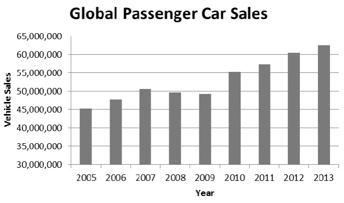
The value of the automotive industry has been estimated by Clearwater Corporate
Finance LLP in the Global Automotive Report 2013 at $800bn [1] and worldwide passenger
car sales exceeded 60 million units in 2012 [2], as shown in Figure 1-1. This is matched by
an increased production of passenger cars to greater than 60 million in 2012, increasing
5.3% from 2011 – a trend that has been sustained for the past decade [3]. Clearly, an
automotive company who can produce high quality products in an efficient time scale can
make large profits in such a market. Automotive products are safety critical by their nature,
are subject to pressure/regulation for the reduction of greenhouse gas emissions and
customer demand for quality and performance at low costs is high. As a result of this,
automotive product development is a complicated process and industry standards such as
[image:21.595.143.486.484.686.2]ISO26262 are widely observed to help manage it [4].
2
A modern luxury passenger vehicle is a highly complex product which includes
numerous state of the art technologies. An ongoing trend in passenger vehicles is the
increased use of electronic and mechatronic systems to carry out functions traditionally
achieved with mechanical/hydraulic systems (such as steering and braking) in addition to
adding new functionality to a vehicle, as demonstrated by a survey carried out in 2010 by
Frede et al [5]. The annual market growth rate for electronics in vehicles is 7% per annum
[6] as the market tends towards comfort, safety and reduced carbon emissions. It was
estimated by Bosch [7] that the value of automotive electronics in the European market
grew from €36 billion to €52 billion with 80% of that growth being new electronic
components and the remaining 20% being replaced mechanical/hydraulic systems. The
outcome of this migration to electronics is the need for highly integrated, safety critical
electronic control systems.
Modern passenger vehicles can have in excess of 100 Electronic Control Units (ECUs)
[8] running 100 million lines of software code controlling the various functions of the
vehicle [9] [10]. This presents a significant challenge to automotive companies who need to
develop these systems quickly enough to remain competitive whilst meeting stringent
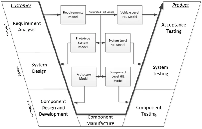
safety and quality standards. The development process for a product in the automotive
industry, in this case an ECU or system of ECUs, follows the classic V model which is shown
in Figure 1-2. The figure has been adapted from Bosch [7] to highlight the use of models in
the development process of a modern product. Models used range from a model
containing the system requirements, derived requirements and test requirements to plant
models of vehicle components such as the engine or electronic components.
Figure 1-2 shows that when testing a product from component level to vehicle level,
the preferred simulation method is Hardware in the Loop (HIL) simulation, which is an
3
multiple ECUs) [11]. Multiple sources demonstrate that HIL is used extensively in the
development of automotive ECUs [8] [12] [13]. To carry out HIL testing, simulation models
of the ECU’s sensors, actuators and loads need to be developed. A derived requirement of
such a model is that it must be able to be simulated in real time because it is interfacing
with a real component. In this project a simulation model of a windscreen wiper system will
be developed for use in the HIL simulation of the body electronics ECU.
Component Manufacture Requirement
Analysis
System Design
Component Design and Development
Component Testing
System Testing
Acceptance Testing
Customer Product
C
o
m
p
o
n
en
t
Sy
st
em
Fu
n
ct
io
n
Requirements Model
Prototype System
Model
Prototype Model
Component Level HIL
Model System Level
HIL Model Vehicle Level
HIL Model
[image:23.595.138.522.257.502.2]Automated Test Scripts
Figure 1-2: V Model for Product Development
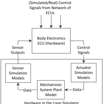
A block diagram demonstrating the HIL testing of a body electronics ECU at component
or system level is shown in Figure 1-3. The ECU is a real component being developed/tested
and is connected to a HIL simulator, inside which are simulation models of the actuators,
sensors and plant dynamics of the component(s) (such as the wiper system) connected to
the ECU1. The HIL simulator contains power and communication I/O which imitate the real
connections to the ECU and the simulation models contained within the simulator simulate
1 Note that the actuators and/or the sensors could also be hardware components interfacing
4
the dynamics of the components, outputting electronic loads and/or communication
signals to be applied to the ECU under test. Numerous test cases can be carried out and
repeated in using this configuration.
Body Electronics ECU (Hardware)
Hardware in the Loop Simulator Actuator Simulation
Models
Mechatronic System Plant
Model Sensor
Simulation Models
Control Signals
Data Data
Sensor Outputs
(Simulated/Real) Control Signals from Network of
[image:24.595.217.437.165.388.2]ECUs
Figure 1-3: Body Electronics ECU HIL Simulation
A block diagram of a wiper system is shown in Figure 1-4. The system’s overall purpose
is to expel water and debris from the windscreen and can be broken down into four parts:
The wiper motor, the linkages, the arms/blades and the windscreen. The wiper motor is a
unique design of a Permanent Magnet Direct Current (PMDC) motor with two electrical
inputs for speed control. The motor is connected directly to the battery meaning that
speed control via changing the input voltage is not possible. The linkages convert the
constant rotational motion of the motor to the two output oscillatory motions of the wiper
blades. The arms and blades combine to achieve the forward and reverse wipe of the
windscreen. Finally, the windscreen protects the driver from rain, debris and wind and
5
Wiper Motor Linkages
Left Arm/Blade
Right Arm/Blade
Vin
Park Switch
Position
Torque Load
Position Torque Load
Torque Load
Environment
Figure 1-4: Wiper System Block Diagram
Currently, the body electronics ECU at Jaguar Land Rover (JLR) is connected directly to a
real wiper system consisting of the wiper motor and linkages, which is known as a
“no-load” wiper system. The disadvantages of this are that new prototypes of the wiper system
are expensive and design updates take time to implement, the no-load system does not
capture the full behaviour of the wiper system but a full wiper system is difficult to
implement in a lab due to space restrictions and water management, and the real
component cannot be used in early, simulation based control design and testing. The
real-time capable model developed in this project alleviates these issues by allowing updates to
be implemented immediately by changing model parameters, capturing the behaviour of
the full wiper system without occupying lab space or needing water management, and
allowing the same plant model to be used throughout the entire control design process.
1.2 Objectives
The main objective of this project is to design a tool to be used by JLR to develop
windscreen wiper models suitable for HIL testing of ECUs to replace the real components.
The tool must allow for modular design, meaning that the different elements of the wiper
system defined above must be modelled separately and they must be able to be connected
to each other. The models must be parametized in a way that is easy to update in order to
6
system whilst being capable of being simulated in real-time. The modelling tool is to be
presented in the form a Graphical User Interface (GUI).
A secondary objective is to develop a controller for the wiper system that maintains the
wiper velocity at a reference speed whilst rejecting the disturbances caused by the torque
load. This will allow the wiper system to be operated at a lower speed, thus reducing the
power consumption and reducing the wear on the PMDC motor brushes.
Concerning the area of HIL simulation as a whole, this project seeks to contribute a
strong and repeatable methodology for developing simulation models of mechatronic
system and investigate ways in which complicated multibody dynamic system can be
simulated in real time. This should improve the effectiveness of automotive HIL testing and
as a result improve the product development process and performance of new vehicles.
1.3 Structure
The remainder of this thesis is structured as described below:
Chapter 2 reviews the background literature pertaining to the work of the project. The review initially focuses on the strategies for automotive product development and how HIL
is used to assist in this endeavour. Subsequently, existing research on wiper systems is
presented and evaluated – highlighting the need for a flexible and real-time capable
simulation model. Specific technical papers are then reviewed on subjects such as friction
in wiper systems, parameter identification and adaptive motor control.
Chapter 3 analyses the structure of a wiper motor and determines how to model the system. Multiple models of the motor are designed and compared and the relationships
between the motor’s parameters are determined. The switching control strategies and
7
Chapter 4 analyses and models the mechanical elements of the wiper system, i.e. the linkages, arms, blades and windscreen interface. Physical and mathematical models of the
systems are synthesised and demonstrated. A model of the friction between the wiper
blades and the windscreen is developed along with a simple model to simulate the effects
of aerodynamic forces on the system.
Chapter 5 shows the work done to identify the unknown parameters of the wiper model. A three stage identification system is developed, starting with a motor transfer
function parameter identification method, followed by a Genetic Algorithm (GA) designed
to identify all of the system parameters and finishing with a local optimizer to refine the
parameters and improve the accuracy of the model.
Chapter 6 shows how the models developed in the earlier chapters are simplified in order to make them appropriate for real-time implementation, and thus suitable for HIL
simulation. The chapter focuses on the use of Artificial Neural Networks (ANN) to
approximate the models. A hybrid physical-ANN model of the wiper system is developed,
along with a full ANN model.
Chapter 7 describes the development of adaptive control strategies for the wiper system to track an input reference speed. The control system is based on a Single Neuron
PID (SNPID) controller with adaptive weights and system gain. The results of the adaptive
controller are compared to a classic PID controller.
Chapter 8 shows the development and implementation of the generic wiper system modelling tool which incorporates the work shown in previous chapters. The tool can be
used by industry to quickly develop and update wiper models for the HIL testing of ECUs.
The dSPACE real-time simulator used to generate validation data for the models is also
8
Chapter 9 concludes the work done in this project and presents suggested further work.
1.4 Publications
Currently, the publications generated by this project are as follows:
M. Dooner, J. Wei, J. Wang, A. Mouzakitis, “Physical Modelling of a Windshield Wiper
Linkage System for Hardware-in-the-Loop Simulation” in The 13th Mechatronics Forum
International Conference, Linz, 2012
M. Dooner, J. Wang, A. Mouzakitis, “Development of a simulation model of a
windshield wiper system for Hardware in the Loop simulation” in Automation and
Computing (ICAC), 2013 19th International Conference on, London, 2013
M. Dooner, J. Wang, A. Mouzakitis, “Dynamic modelling and experimental validation of
an automotive windshield wiper system for hardware in the loop simulation”, Systems
9
Chapter 2
- Literature Review
2.1 Introduction
This chapter presents a literature review of the previous work done in this project’s
research area. The chapter begins by investigating the use of HIL simulation and model
based design in the automotive industry, and how it has evolved from a concept to an
essential part of product development. Examples of how HIL improves the process of ECU
development in the automotive industry are given. The purpose of this section is to give
justification and scope to the work carried out in this project.
Following the investigation of HIL and model based design, a review of the current
windscreen wiper models and control schemes available in the literature is given. This
section also includes a review of papers published regarding previous work in this project.
The purpose of this section is to demonstrate the need for a flexible, real-time wiper
model.
The subsequent sections are concerned with reviewing previous work pertaining to the
technical aspects of this project. Papers concerning online and offline parameter
identification are reviewed in order to identify the best methods to apply to this project.
Papers concerning the identification of the friction between the wiper blades and the
windscreen are presented and methods of modelling the friction are explored. Also the
aerodynamic elements of wipers are researched and discussed. Finally, the adaptive
control of DC motors is reviewed and its application to a wiper motor discussed.
2.2 Automotive Product Development: HIL and Model Based
Design
In 1999 a paper entitled “An investigation into the use of hardware-in-the-loop
10
explored the feasibility of using HIL to develop ECUs. Previous methods of ECU and vehicle
development relied on physical prototypes of vehicle components; however this method
was becoming less fit for purpose as the amount of electrical components and controller
complexity in vehicles increased. HIL simulation was recognised as a possible solution for
modernising the development of ECUs, with the authors of [14] citing a 1993 SAE paper
called “Hardware-in-the Loop Simulation as a Standard Approach for Development,
Customization, and Production Test of ECU's” [15] as evidence of this. The authors of [14]
developed three separate plant models of the three subsystems of the Driver Door Module
(DDM), namely the mirror, window and lock subsystems (building on work by the same
authors previously published in [16]). The models were developed using Matlab/Simulink
and it is stated that it is the introduction of Stateflow to the Simulink tool suite that
facilitated the modelling of automotive subsystems in this way. State charts were already
used in developing vehicle body electronics software, such as in [17] where a state model
of a wash/wipe system was demonstrated, and the inclusion of a state chart simulator in
Simulink greatly improved its suitability for vehicle body electronics modelling. The work
demonstrated that, with relative ease, simple off-line plant models could be converted to
online models and uploaded onto a real-time simulator and simulated in real time. The
paper concludes that HIL can make a positive difference in ECU development and has the
potential to be implemented in the future.
A review carried out in 2006 called “Review of hardware-in-the-loop simulation and its
prospects in the automotive area” [18] confirmed the conclusion of the authors of [14]. The
review found that, in the automotive industry, HIL is the preferred method of ECU testing,
development and calibration. The paper also discussed other applications of HIL, with the
focus being on an Engine in the Loop (EIL) system in which a real engine is interfaced with a
simulated vehicle for testing and development. The review also highlighted that systems of
11
modelled independently and then tested in a connected system. A survey of 80 technical
papers in 2007 [12] confirms that HIL is now widely employed in ECU development in the
automotive industry. The paper also states that there is a trend towards model based
design, which is a recurrent theme amongst recent publications in the area of ECU
development.
The advantages of using HIL over traditional prototype based production development
methods are explicitly stated in references [19], [8] and [14], amongst others. The main
advantages listed are 1) The ability to carry out testing in pre-production stages, 2) The
ability to develop and test systems concurrently without having to wait for prototypes, 3)
Dangerous and/or extreme condition tests can be carried out safely and easily repeated
and 4) Tests can be standardized and automated.
Model based design of automotive ECUs generally refers to developing the control
software in three stages: Model in the Loop (MIL), Software in the Loop (SIL) and HIL
(sometimes Processor in the Loop (PIL) is used). References [20] and [21] give details as to
how this process works. MIL refers to designing a control system and its associated plant
model(s) in a simulation package such as Simulink and running test cases purely in
simulation. Once a suitable control system has been developed, the controller model is
compiled into production code (usually via automated methods) and simulated with the
plant models used in the MIL testing stage. This is the SIL stage. Exactly the same test cases
can be applied in both stages. Finally, the code tested and developed in the SIL stage can be
implemented in an ECU (HIL) or another processor (PIL) and once again tested with the
same test cases and plant models as before. This back to back testing procedure allows
thorough testing of the controller before it is implemented, potentially saving time and
12
standards such as ISO26262 [4] [22] due to its iterative nature and traceability of results
[23] [24].
It can be seen that HIL and model based design have become popular tools in ECU
development and, as has been previously stated, this is largely down to the increase in
electronics in modern vehicles [6]. In 2006, top of the range vehicles could have up to 70
interconnected ECUs controlling the various functions of the vehicle [8]; the number is now
around 100 ECUs operating on an estimated 100 million lines of code [9]. It is also found
that the majority of issues with vehicles that require OEM recall are electronics based,
leading to increased pressure to improve the quality of testing in the design stage [13].
In summary, HIL and model based design have become important tools in automotive
ECU testing, and numerous examples of their application are available in the literature,
many of which are available from dSPACE: [25], [26], [27] and [28] are given as examples.
2.3 Current Wiper System Models and Research
This section explores current research into the wiper system and the models currently
in the literature. The purpose is to justify the need for a real-time capable wiper model that
models the system from the perspective of the wiper motor I/O. Note that research
relating specifically to the friction between the blades and windscreen is discussed in
Section 2.5 .
2.3.1 Vibration Analysis and Mitigation Research
The majority of the research in the area of windscreen wipers concerns the vibrations
in the system. This research can further be split into modelling, measurement and
reduction through control techniques or mechanical design. In 2000, a paper called
“Dynamic Analysis of Blade Reversal Behavior in a Windshield Wiper System” [29] was
13
system’s linkages, arms and blades. The purpose was to analytically investigate the causes
of reversal noise (the noise caused by vibrations when the blade reverses its direction) and
investigate ways to reduce it. The paper found that the angles and clearances between the
wiper rubber and the blade had a large effect on the reversal noise, but also on other
sources of noise in the system. The model is a complex multibody dynamic model which is
not suitable for real time simulation and models behaviour that is not significant for the
model to be developed in this project. Two later papers with shared authors to [29] used a
similar model to investigate and mitigate squeal noise2 in the wiper system [30] [31]. Both
papers used measurements, FEA and mathematical models to investigate the noise. They
concluded that it could be reduced by changing the configuration of the wiper (as in [29]),
material choice and surface treatment. The three papers clearly show that multibody
dynamic modelling is capable of modelling the wiper system to a higher fidelity than is
needed in this project.
In 2002, chatter vibrations3 were investigated in the paper “Simulation of Chatter
Vibrations for Wiper Systems” [32] using a similar technique to the previous papers
discussed. A mathematical model was developed and validated with real data to determine
the factors affecting chatter vibrations. It was found, as in [31] [30] and [29], that the
geometry of the blade and the rubber material had the biggest impact. Chatter vibrations
were also investigated in [33] which used a validated finite element model to accurately
simulate the system. Instabilities in the system that caused the chatter vibrations were
then found using a complex eigenvalue method. The paper then proposes structural
modifications to mitigate such vibrations.
A common method used to reduce friction induced vibrations is input shaping control.
Input shaping is a control technique used to remove vibrations by combining impulse
2 Defined as the high frequency vibration of the wiper system (around 1000 Hz) 3
14
signals, designed to cancel vibrations, with the normal input command. In a 2008 paper
called “Application of Input Shaping Control Strategy for Reducing Chatter Noise in the
Automotive Wiper System” [34], the model developed in [29] was used to design an input
shaping control system to reduce chatter noise. The vibrations that caused chatter were
reduced by 30%. A paper released in 2010 with some shared authors with [34] follows a
similar approach to [34] in order to use input shaping to reduce reversal vibrations with the
same results (i.e. 30% decrease in vibrations) [35]. Similarly, in [36], input shaping is used to
reduce unwanted vibrations. In this case, a particle swarm optimisation algorithm was used
to time and shape the impulses in order to optimise the controller. Reduced vibrations
were observed. Finally, in a paper entitled “Practical multi-objective controller for
preventing noise and vibration in an automobile wiper system” [37], unwanted vibrations
were reduced using input shaping, whose impulses were optimised using a Genetic
Algorithm (GA). The model proposed in [29] was used to generate I/O data to train a
recursive Artificial Neural Network (ANN) which was then implemented in the control
system. A similar technique is used in this thesis to produce a real-time capable model. A
collective weakness of these papers is that none of them implement the input shaping
control in a real system, which will be driven by a wiper motor with its own dynamics. In
reality, achieving an accurate target velocity is difficult to accomplish (see Chapter 7).
Other papers investigating vibration in wiper systems include [38] and [39], which
specifically concentrate on how friction induces vibration using models and experimental
measurements. Paper [38] concluded that squeal noise could be explained and modelled
using the Stribeck friction effect. Paper [39] concurs with this, demonstrating that it is the
negative friction-velocity curve at low velocities that causes the instabilities. Paper [40]
takes experimental measurements of friction induced vibrations using microphones. The
paper concluded that the wetness of the windscreen directly affected the amplitude and
15
“Dry” and “Half-Dry/Tacky” windscreen conditions that are used in this project. The chaotic
modelling and control of the wiper system have been studied by Chang and Lin in [41] and
Chang in [42]. These papers serve to demonstrate how complex the behaviour of a wiper
system can get, but are out of the scope if this project.
In general, the papers researching the vibrational behaviour and control of a wiper
system present models that are too complicated to be used in this project, but do serve as
a useful tool for understanding the behaviour of a wiper system and as starting points for
simpler models. A general weakness in most vibration based papers is that they do not take
into account the wiper motor, and thus are ignoring an integral part of the system which
has an effect on the dynamics and the potential control solutions.
2.3.2 Control of Wiper Systems
A paper entitled “Research on Passenger Car Windscreen Wiper Controller and Control
Method Based on CAN” [43] designed a control system which operates using the Control
Area Network (CAN) bus, which is used in electric vehicles. The idea is to replace older
control systems, which tend to route power via switches, with a network based control
method. Most modern vehicles employ wiper control based on CAN, the specifics of which
depend on the vehicle model.
Most wiper systems work using one motor to drive both wiper arms; however some
research is carried out into controlling systems with separate motors driving each arm4. The
control challenge in this case is to synchronise the wipers to avoid collision. A recent paper
released in 2015 [44] reviews current proposed control methods and suggests its own
method using a Peripheral Interface Controller and an FPGA, although no details or results
are provided. The most relevant paper cited by [44] is “On the Synchronization of a Pair of
4 An advantage of this style of wiper system is the reduction in weight, noise and mechanical
16
Independent Windshield Wipers” [45] which models a two motor wiper system and
controls the motors using reference trajectory planning and PID controllers. Current
research on these types of wiper systems is limited to simulation.
A project is reported in [46], published in 2014, which developed an automatic system
which controls the wipers using a rain and dust sensor and the sun visor via a light sensor.
The purpose of the project is to fully automate the driver’s visual comfort. It is likely that
such systems will be implemented in future vehicles, for example many modern vehicles
already implement a rain sensor.
2.3.3 Dynamic Models of Wiper Systems
The literature contains some dynamic models of wiper systems that share similarities
with the model developed in this project. The paper “Dynamic Modeling and Control of the
Windshield Wiper Mechanisms” [47] details the design process and control of a complete
wiper system. The design and synthesis of the mechanical elements is implemented in the
3D modelling suite CATIA, with the geometry then transferred to the multibody dynamics
modelling tool ADAMS for simulation. The ADAMS model is then co-simulated with a
standard PMDC motor model and control system designed for controlling the motor
velocity which are simulated in Matlab. The number of CAD packages used in this design
process could be reduced by using the physical modelling tools in Simulink, streamlining
the process. The controller is based on PID control and achieves good results in the test
case shown, however only one ideal test case is presented, whereas a real wiper system
undergoes dynamic torque loads and is required to be operated at multiple speeds.
A paper published in 2011 [48] develops a model of the wiper system’s mechanical
elements using the mechanical physical modelling tool in Simulink, called SimMechanics.
The model does not include the motor, nor is it validated against real data, but the paper
17
SimMechanics will be utilised heavily in this project. The SAE paper [49] also reports a
modelling system whose purpose is to aid the design of the mechanical element of the
wiper system, although details of the system are not given. The paper presents results that
indicate the dynamics of the wiper system and can be used as an early validation of the
models developed in this project.
Finally, two papers have been published that report work previously carried on this
project. These are: “Vehicle windscreen wiper mathematical model development and
optimisation for model based hardware-in-the-loop simulation and control” [50] and
“Accurate Model Based Hardware-in-the-Loop Test for a Windscreen Wiper System” [51].
Both report a “no-load” model5 of the wiper system, whose unknown parameters are
identified with a GA. The models successfully simulate the positional elements of the
linkages; however the torque load is identified as constant, which is untrue. Also the motor
equations do not model the two speed functionality essential for wiper motor operation,
and the parameters for the transient conditions are incorrect, i.e. the motor takes many
seconds to settle into steady state, whereas in reality it takes less than a second. This
project will take the models presented here and add flexibility, fidelity and functionality to
them.
The analysis of the literature concerning automotive product development and current
wiper models has shown there is a gap in the literature for model of a windscreen wiper
system that accurately represents the behaviour of the system which can be simulated in
real-time, making it suitable for HIL simulation, to be developed.
5 A model of the wiper system that only includes the wiper motor and the linkages, i.e. the arms,
18
2.4 Parameter Identification
2.4.1 Off-line Parameter Identification using Genetic Algorithms
Genetic Algorithms were introduced by Holland in 1975 [52] and have since been
developed by numerous authors such as Goldberg [53]. They have become a popular tool
for solving optimisation problems (such as parameter identification) and are applied in this
project to identify the motor and friction parameters of the wiper system. The advantages
of GAs are that they are well suited to solving non-linear and non-differentiable problems
and are less susceptible to convergence on local minima than local optimisers [54].
GAs have been used in previous work on this project in papers [51] and [50] and there
are many examples of them being used for parameter identification across the literature.
Some examples are [55] – which showed that GAs can outperform a Least Squares
Estimation (LSE) algorithm in PMDC motor parameter identification, [56] – which
successfully identified the parameters of an induction motor using a GA and [57] – which
used a GA to identify the parameters of a coal fired supercritical power plant. It can be seen
from the examples that GAs can identify the parameters of complex models.
2.4.2 On-line Parameter Identification
The parameters of the wiper system are subject to change during operation due to
factors such as wear and temperature changes. This is not an issue for a model to be used
in HIL; however control systems based on state estimators rely on model parameters to
estimate unknown states, such as the velocity of a DC motor. The paper “Sensorless speed
control of DC servo motor using Kalman filter” [58] gives an example of using a Kalman
filter to estimate the speed on a DC motor using measured voltage and current data along
with a mathematical model of DC motor. The system performs well in ideal conditions but
19
Similarly, a paper published in 2010 [59] uses an observer to estimate the velocity of a
DC motor, however in this case the resistance and inductance were estimated online using
a Recursive Least-Squares (RLS) algorithm. This technique is relatively common in
sensorless motor control [60] [61]. However, it is difficult to implement in this project due
to the dynamic and unmeasured torque load and models based on physical modelling and
ANNs.
Implementing sensorless speed control is suggested as further work in this project.
2.5 Friction in a Wiper System
One of the defining features of a windscreen wiper system is the friction between the
rubber wiper blade and the glass windscreen. Friction is the dominant force contributing to
the torque load acting on the wiper motor. For these reasons, and for the facts that friction
has an effect on the lifetime of wiper blades, vibration and wiping performance, a lot of
research into the friction in wiper systems is carried out. In addition, research into friction
in general is active and has been for decades through numerous research streams such as
physics, tribology, modelling and control. This review, and subsequent modelling work, will
focus on the issues of defining and modelling friction, and friction specifically relating to
wiper systems.
In 1968, Dahl released a much cited paper considering the physical phenomena causing
friction and presented a simulation model for mechanical systems undergoing sliding (or
rolling) motion [62]. The solution models three elements of friction: Static friction,
Coulomb friction and Sliding/Rolling friction. Static friction is the force that must be
overcome before a body subject to an external force will begin to move. Coulomb friction is
the constant resistive force experienced by a moving body; its magnitude is less than that
of static friction. Sliding or rolling friction (depending on the nature of the mechanical
20
of the body. This model has been widely used (and developed further) when simulating and
controlling mechanisms or machines, as demonstrated in the survey paper entitled “A
survey of models, analysis tools and compensation methods for the control of machines
with friction” [63].
In 1994, the first survey on friction compensation that brought together research from
numerous fields of study was published [63]. The study cites 280 research articles and
examines many aspects of friction, from its cause to suitable compensation methods. In
this project, certain conclusions of the survey should be taken into account: 1) There should
be a theoretical as well as experimental justification for the friction model used in order to
validate any assumptions and simplifications made. To satisfy this, research articles
specifically in the area of windscreen wiper friction are studied. 2) Lubrication must be
considered. This conclusion specifically refers to engineering lubricants and their effect on
a system; however in the case of a wiper system the water on the windshield will have a
large effect on the frictional force. 3) Analyses must be verified across the full range of
application. The inevitable simplifications made due to the complexity of friction as a
phenomenon mean that any model developed in this project must satisfy experimental
data across all speeds and wetness levels to ensure that the simplifications are valid.
The paper “Friction Models and Friction Compensation” published in 1998 [64] briefly
covers existing friction models, generally splitting them between static models6 and
dynamic models. Dynamic models take into account the hysteresis effects of friction, such
as a lower friction force for decreasing velocities than for increasing. Most of the dynamic
models given in the paper are extensions of the Dahl model.
6 Most static models of friction are in fact dynamic since they are functions of velocity due to
21
A widely used friction model based on approximating the surface contact between two
materials using the action of bristles was introduced in [65], and is also described in [66].
The purpose of the model was to capture the hysteresis effect of friction observed as the
velocity oscillates around zero. If this effect is not taken into account the performances of
friction models are poor at low velocities and are thus unsuitable for precise feedback
control. The proposed brush model is an example of a dynamic friction model, which
perform well at low velocities. Due to the nature of the model developed in this project, it
is unlikely that a dynamic model such as this is needed. Also, dynamic models tend to be
computationally expensive, which is unsuitable for HIL.
Identification of friction model parameters is an important aspect of friction modelling.
A 2007 paper by Borsotto et al [67] considers the static and coulomb forces to be the most
important and identifies them using a limit cycle method. A paper by Fujii [68] shows a
method to dynamically measure the coefficient of friction between two bodies (using a
wiper blade as an example) by measuring the inertial forces acting on the masses. In a
paper by Nakajima et al [69], a GA was successfully used to identify friction coefficients.
This method will be employed in this project. Similarly Kim et al [70] used an accelerated
genetic algorithm to identify the parameters of a seven parameter friction model.
Papers studying friction specifically in wiper systems are now considered.
A paper by Bodai et al [71] investigates the friction force measured at the windscreen
and wiper blade contact area using a rotating cylinder of glass in contact with a wiper
blade. The paper largely focuses on explaining erroneous results by using an analytical
model to demonstrate eccentricities in the cylinder of glass. However, the paper also gives
results of a measured friction coefficient for different slip speeds and normal force
components. The coefficient decreases with decreasing normal force and also with
22
which suggest that that the friction force increases with speed. These results correspond
with a later paper by the same authors [72] which uses finite element modelling and
experimental measurements to investigate sliding friction of a wiper blade.
Work done by Buta [73] measured the friction force of a wiper blade at three different
speeds in wet and dry conditions. The results suggested that the friction increases with
speed, which disagrees with [71] and [72], and is higher in dry conditions.
A 2009 paper by Deleau et al [74] attempts to measure sliding friction between a wiper
blade and glass in wet, dry and tacky conditions. The results show a largely linear
relationship between the normal force applied to the blade and the frictional force. In
agreement with [71] and [72], the results also show an initial increase in frictional force
with velocity up to around 100mm/s, followed by a constant or decreasing force as speed
increases. The paper also shows that for a constant force and speed, the friction
force/coefficient is at its lowest in the windscreen’s wet condition, the highest in its tacky
condition and second highest in the dry condition. This is agreement with [73].
A 2007 paper by Koenen et al [75] agrees with [74] and [73] by showing that the
coefficient of friction is highest when the windscreen is tacky, lowest when wet and
medium when dry. The paper shows results giving a higher wet coefficient of friction at low
speeds which level out at higher speeds. This agrees partially with [71] in that at 100mm/s
the coefficient of friction levels out, however in this case it seems to rise slightly as the
velocity increases. Also, an increased load causes a decrease in the coefficient of friction in
wet conditions.
In Chapter 4 data from the papers [72], [68] and [75] is plotted and used to develop a
dynamic friction model to apply to the wiper model. A six parameter continuously
23
developed in this project. A dynamic friction model is developed instead of, for example, an
average friction or worst case friction model for a number of reasons. Firstly, it allows the
model to be used to analyse the dynamic current load on the vehicle’s battery. Secondly,
the load dynamics of the system can be modelled to a higher accuracy, allowing the
development of control systems (such as that shown in Chapter 7) that can adapt to
changing load conditions. Finally, the addition of the dynamic friction model does not add a
large burden on simulation time when compared with other elements of the model,
particularly the multibody dynamic element calculating the position and inertial forces of
the mechanical system.
2.6 Vehicle and Wiper Aerodynamics
There is a large amount of work and research conducted into the aerodynamics of
vehicles due to the fact that the aerodynamic design has such a great effect on the
performance of the vehicle. In general, the study of vehicle aerodynamics is out of the
scope of this project; however the forces experienced by the wiper system when the
vehicle is moving will have an effect on its performance. This section begins by giving some
example studies on vehicle aerodynamics to demonstrate the general process of
developing and validating models, and then gives details on papers specifically related to
the aerodynamic forces experienced by the wipers.
A paper published in 1993 called “Aerodynamics of road vehicles” [77] gives a good
overview of the implications of aerodynamic forces on vehicles, such as drag and trailing
vortices, and how they affect the design of vehicles. Importantly, the use of Computational
Fluid Dynamics (CFD) as a method of design and testing are discussed. The reference
models used in the CFD simulation of vehicles are studied in [78], which shows how the
complexity and fidelity of the models have increased as the technology has developed and