Sharif University of Technology
Scientia IranicaTransactions B: Mechanical Engineering www.scientiairanica.com
On a conceptual method for the extraction of wind
energy using airfoil and linear generator
H. Darijani
and A. Panahi
Department of Mechanical Engineering, Shahid Bahonar University of Kerman, Kerman, P.O. Box 76175-133, Iran. Received 2 October 2014; received in revised form 31 August 2015; accepted 25 April 2016
KEYWORDS Wind energy; Airfoil;
Linear generator; Kinematic and kinetic analysis;
Output power.
Abstract. In this paper, a new conceptual method is introduced in order to extract wind energy using a set of airfoils and a linear generator. Indeed, the idea of this method is inspired by the ocean wave energy extractor and the linear wind generator. In this method, under wind velocity, a mover connected to the airfoils undergoes a linear reciprocating motion such that this motion is converted to electricity using the magnetic eld of a linear generator. Moreover, the structure and mechanism of the proposed method are illustrated. Based on this illustration, a perfect kinematic and kinetic analysis of the mechanism, including the displacement, velocity, acceleration, force, and mechanical powers, is done. Finally, the average generative power based on the proposed method is investigated under dierent conditions and compared with the output power of the ocean energy extractors in similar situations. The most important advantage of the proposed method in comparison with the two mentioned methods is its simplicity, high eciency, and compatibility with all wind situations.
© 2017 Sharif University of Technology. All rights reserved.
1. Introduction
Electricity generation from fossil fuels has caused a lot of issues aecting atmosphere, public health, etc.; thus, urgent and strategic measures should be taken to overcome these emerging hazards by focusing more and more on renewable sources of energy [1]. Obviously, these problems can be resolved by the use of natural sources that are renewable, economical, available, and sustainable for the environment. However, the actual renewable technologies up to now have had no such potentials. As a result, many attempts have been conducted in order to utilize wind [2], ocean wave [3,4], solar cells [5] etc. as green energy sources. One of the most well-known examples is windmills or wind turbines that are used as a representative approach to harness wind energy in great amount. Wind farms have
*. Corresponding author. Tel.: +98 341 2114041; Fax: +98 341 2120964
E-mail address: [email protected] (H. Darijani)
problems of land occupation and environmental impact because of the fact that their electrical production depends on the amount of area they occupy [6]. To overcome these problems, Milanese and Ippolito [7] have developed a new class of wind energy generators named \Kitegen".
There are many obstacles to Kitegen project development due to the main problems wind creates for controlling the trajectory of kite and its stability [8-10]. Up to now, there are rare methods to utilize this project eciently. Consequently, there has been much consideration regarding Kitegen project in the recent years in order to extract wind energy using this method, practically. For example, Laddermill [11-12], with similar situations to Kitegen is one of the used technologies. In the Laddermill structure, there are many kites which are connected to a main rode that is twisted around a drum attached to the generator.
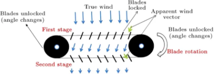
Another important method, which has been in-troduced based on Kitegen operation principle, is linear wind generator (see Figure 1) [13]. Linear Wind
Gener-Figure 1. The mechanism of LWG for extraction of wind energy.
ator (LWG) is an ecient method for the wind energy harnessing process. For equivalent swept area of wind, the LWG can generate twice the amount of electricity by the Wind Turbine Generator (WTG). Also, LWG, in comparison with WTG, has simple structure and can produce electricity within a signicantly small land area with a substantially lower cost. In LWG, the mechanism of converting linear motion to rotational motion and the mechanism of changing the angle of attack lead to energy dissipation because of their complexity [14].
Recently, a renewable energy extraction method has been developed that converts the ocean wave energy to electricity [15]. Although energy extraction using the ocean waves is interesting and can be used for special applications, this technology suers from some drawbacks such as corrosion, high cost of manufactur-ing, high requirement for installation and construction, economical consideration, etc. [16].
Great attention has been focused on renewable energy production in both industry and academic research. In these methods, as we explained and mathematically modeled with simpler assumptions in our recent research [17], low energy dissipation, low cost, simplicity, and high performance are highly re-garded. Along this line, in this paper, a new conceptual method is proposed for extraction of renewable energy from wind. In fact, the mechanism of this method is the combination of two recent technologies, namely, the ocean wave energy extractor and the linear wind energy. The main parts of the mechanism, including a linear generator, a set of airfoils, and a ywheel, as well as the relative motion of these parts, are explained. Moreover, a perfect kinematic and kinetic analysis of this mechanism, including the displacement, velocity, acceleration, force, and mechanical powers, is per-formed. Finally, in order to evaluate the performance of the proposed method, the net generative power is determined for dierent cases and compared with those of the ocean energy extractors in similar situations.
2. The mechanism of the proposed method Figure 2 shows a scheme of the mechanism of the proposed method for extraction of renewable energy from wind.
Figure 2. Schematic of the proposed mechanism for extraction of wind energy.
As shown in Figure 2, structure of the proposed mechanism for production of wind energy has three main parts including a set of airfoils, a linear generator, and a device for saving energy (ywheel or spring). The object connected to the set of airfoils (mover) has a linear reciprocating motion. Each cycle of reciprocation consists of two opposite motions: There is a motion in one direction, and then a motion back in the opposite direction. Here, reciprocating motion is a repetitive up-and-down linear motion. The operation of the proposed mechanism is demonstrated for two half cycles, including upward and downward motions. In the upward motion, the angle of attack of the airfoil should be changed such that the maximum upward lift force is exerted on airfoil. In this half cycle (upward motion), the ywheel saves the required energy for changing the angle of attack at the end of the motion. When the airfoil reaches its maximum level in the upward motion, the energy saved in the ywheel should be able to change the attack angle such that the maximum downward force is exerted on airfoil. It is notable that the attack angle of airfoil in downward motion should be opposite to that in upward motion. For both upward and downward motions, the lift forces exerted on airfoil have the same amount and are in the direction of the airfoil motion. Changing the angle of attack at the end of upward motion results in a downward force on airfoils, leading to their movement in downward direction (see Figures 3 and 4). Hence, by attaching an object to the set of airfoils (named as mover), a linear reciprocating motion is produced. This motion in the magnetic eld of the linear generator can generate the electricity. Due to the geometrical magnetic anisotropy of the generator, the perpendicular and parallel forces in the wind direction exist in the linear generator. Existence
Figure 3. Direction of lift force in the upward motion.
Figure 4. Direction of lift force in the downward motion.
of ywheel is necessary to maintain continues motion and homogenize anisotropy forces.
2.1. Conversion of energy in linear generator Eq. (1) describes the relation between the magnetic ux and magnetic eld () through an area, ~a, in a magnetic eld, ~B, in which the integral is taken over the area:
= I
~
B:d~a: (1)
The process of induction has been described in a well-known relation by Faraday that if the magnetic ux, , through an area enclosed by a conducting loop changes with time, a current and an electromotance (emf) are produced in the loop; this process is called induction.
Figure 5. Schematic of linear generator.
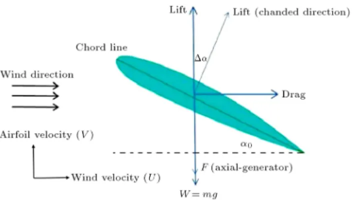
Figure 6. The main forces that act on airfoil in presence of wind.
The induced emf is [15]:
e = d()dt ; (2)
where e indicates electromotance.
Based on Eq. (2), the voltage induced in a close circuit is equal to the minus time derivation of total ux enclosed by the circuit. The minus sign indicates that the direction of the current induced in the circuit is opposite to the direction of increasing ux.
Figure 5 shows the operation mechanism of linear actuator according to Eqs. (1) and (2), which are the fundamentals of a linear generator in the reverse manner.
Because of the reversible nature of the electrome-chanical energy transformation process, actuators may work as linear electric generators, in which mechanical energy is converted into electrical energy. The energy conversion equation is demonstrated in the following:
~F:~V = ":I; (3) where ~F is net mechanical force, ~V is mechanical velocity, " is voltage, and I is current.
2.2. Lift and forces on an airfoil
Figure 6 schematically shows an airfoil installed in wind direction.
It is assumed that the airfoil can move only vertically and its speed is v. The wind is blowing in uniformly horizontal direction with speed, u. When the airfoil moves upward at a speed of V , the surrounding air moves downward relative to the airfoil with the same speed. To the oncoming air ow, the angle of attack of the airfoil can be obtained using of the following equation:
= 0+ tan 1uv
: (4)
In absence of wind, the angle of attack of airfoil is 0
and after the airfoil senses wind, the angle of attack increases as amount of tan 1(u
v) increases.
The lift force of the airfoil in the direction normal to the ow has the expression:
L = 12SCL(u2+ v2); (5)
where is air density, S is the projected area of airfoil, and CLis the lift coecient of the airfoil [16].
From basic aerodynamics, it is well known that the lift coecient increases by enhancement of the angle of attack up to stall point. It should be mentioned that the lift will be reduced if increase in the angle of attack continues.
In this study, for simplicity, the thin airfoil theory is used in which lift coecient has a linear relation with angle of attack as follows:
CL= 2: (6)
It is necessary to avoid very high angle of attack due to the eect of induced drag that causes exerting an undesirable force in direction of air ow. Consequently, should be selected in a certain range in order to avoid stall phenomena. Also, based on the available data and considering the assumption of Thin Airfoil Theory, the airfoil is a symmetric NACA0012.
3. Kinematic and kinetic analysis of the proposed mechanism
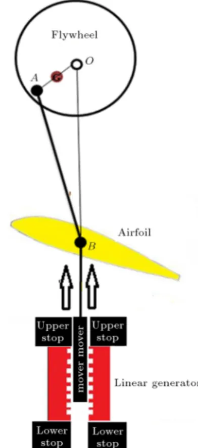
In this section, the kinematic and kinetic analysis of the proposed mechanism is done with only one airfoil instead of a set of airfoils (see Figure 7). As it can be seen in this gure, the basic nature of the proposed mechanism and the relative motion of its parts can be described with the aid of the slider-crank mechanism, which consists of crank shaft (ywheel), the connecting rod (rigid rod AB), and slider block (mover and airfoil). 3.1. Kinematic analysis
The mechanism is geometrically illustrated in Figure 8. The parameters r, e, and L are the radius of ywheel or length of the crank OA (distance between the two
Figure 7. Schematic of the mechanism of the proposed method for extraction of wind energy.
Figure 8. The relative position of parts of the mechanism during its upward motion.
cylindrical joints O and A), the distance between the center of mass ywheel (Point \G") and its rotation center, and the length of connecting rod AB, respec-tively. and are the ywheel angle and connecting rod angle connecting rod's angle with respect to the vertical line.
The mechanism is driven by lift force exerted by wind and the positive rotation direction is dened to be clockwise. The kinematic analysis of mechanism is done for two half cycles including the upward motion and the downward motion, separately.
3.1.1. Kinematics of the upward motion
In Figures 9 and 10, when the mover contacts with the lower stop, the ywheel angle is referred to as = 0. At the angle = 0, the mover begins to leave the lower stop and at = , the mover touches the upper stop. From the angle = 0 to = , the motion of mechanism is the so-called upward motion and z is the distance of the mover from the lower stop. The relation between the ywheel angle, , and the mover displacement from lower stop, z(t), can be determined from the geometry of the mechanism in terms of the length of the connecting rod, L, and the radius of ywheel, r. Considering triangle OAB and using the Cosine rule, it can be expressed that:
(AB)2= (OB)2+ (OA)2 2(OB)(OA) cos : (7)
Figure 9. The relative position of parts of the mechanism during its downward motion.
Figure 10. The Free-Body Diagram (FBD) for the ywheel (assumed to be a circular disc).
Then:
cos = 1
zL z22
r2+ rL rz = G(z);
sin =p1 cos2: (8)
It is clear that = 0 for z = 0 and = for z = 2r. Also, from the geometry of triangle OAB, based on the Sine rule, we have:
sin =(r sin )L ; cos = s
1 Lr22sin2: (9)
Taking the rst derivatives from both sides of Eq. (8), with respect to time, gives the relation between the velocity of the mover ( _z) and the angular velocity of the ywheel ( _) as follows:
_ sin = _z ddz(G(z)): (10) Taking the second derivatives from both sides of the earlier Eq. (10) with respect to time gives the relation between the acceleration of the mover (z) and the angular acceleration of the ywheel ( ) in the form of:
sin = _2cos +zd
dz(G(z))+ _z2 d2
dz2(G(z)): (11)
3.1.2. Kinematics of the downward motion
In Figure 9, when the mover contacts with the upper stop, the ywheel angle is referred to as 1= 0. At the
angle 1= 0, the mover begins to leave the upper stop
and at 1= , the mover touches the lower stop.
From the angle 1= 0 to 1 = , the motion of
mechanism is the so-called downward motion and z1(t)
is the distance of the mover from the upper stop. The relation between the ywheel angle 1 and the mover
displacement from lower stop z1(t) can be determined
from the geometry of the mechanism in terms of the lengths of the connecting rod, L, and the radius of ywheel, r. From the geometry, considering triangle OAB and using the Cosine rule, it can be expressed that:
cos 1= z1L + z2
1
2
rL r2+ rz1 1 = G1(z1);
sin 1=
p
1 cos21: (12)
Based on the Sine rule in triangle OAB, we have:
sin 1=r sin L 1; cos 1=
r
1 Lr22sin2 1: (13)
Derivative of Eq. (12) with respect to time gives the relation between the velocity of the mover ( _z1) and the
_1sin 1= _z1dzd
1(G1(z1)): (14)
Derivative of Eq. (14) with respect to time yields the following relation in the form of:
1sin 1= _12cos 1+ z1dzd
1(G(z1))
+ _z2 1 d
2
dz2
1(G1(z1)): (15)
3.2. Dynamic analysis
The inertia parameters of the mechanism are shown in Figure 9. m1, M, m, and Io represent the masses of
the ywheel, the airfoil, the mover, and the moments of inertia of the ywheel, respectively. Also, for simplicity, mass of the connecting rod is ignored. Similar to the kinematic section, the kinetic analysis is done for cycles of upward and downward motion, separately.
3.2.1. Kinetics of the upward motion
Figures 10 and 11 represent the Free-Body Diagrams (FBD) and kinetic diagrams for the ywheel (assumed to be a circular disc) and set of the mover and airfoil (slider) of the mechanism, where the input motion is provided by the lift force exerted by wind. The ywheel exhibits pure rotation about pivot \O". From the FBD and the kinetic diagram in Figure 10, Euler's rotational dynamics equation yields:
X
MO = IO ) T sin( + )r + mge sin
= IO; (16)
wherePMO is the moment of forces about the point
\O" and T is the internal force in the connecting rod. Using Eq. (16), we have:
T = r sin( + )IO r sin( + )mge sin : (17)
Figure 11. The free-body diagram for the set of the mover and airfoil of the mechanism.
Set of the mover and airfoil exhibits pure translation along the z-axis. From the FBD and kinetic diagram in Figure 11, the Newton's Second Law for this set may be represented as:
X
Fz=MaG)T cos +FL Mg Faxial=M z; (18)
where Faxialis the force exerted on the mover from the
linear generator, which acts in an opposite direction to the movement as it moves across linear generator. Referring to Ghita et al. [18], the simulation results for calculating forces due to magnetizing eld of a typical linear generator show that the value Faxial is
approximately 17.19 N.
Substituting Eq. (17) into Eq. (18), the governing dynamic equation can be expressed as follows:
"
IO + mge sin
r(sin cos + cos sin ) #
cos
+12CL(u2+ _z2)S Mg Faxial= M z: (19)
Based on the kinematic analysis and using Eqs. (8)-(11), the governing dynamic equation (Eq. (19)) be-comes a nonlinear ordinary dierential equation in terms of z, _z, and z and the initial boundary conditions are given as follows:
z(0) = 0 and _z(0) = 0: (20) Numerical solution to this initial boundary value prob-lem is provided using the Maple software.
3.2.2. Kinetics of the downward motion
Figure 12 represents the Free-Body Diagrams (FBD) and kinetic diagrams for the ywheel and set of the mover and airfoil of the mechanism in the half cycle of downward motion. In this cycle, since the angle of attack of airfoil becomes , the direction of the lift force exerted by wind is in the direction of the gravity force. Thus, it is expected that the design of mechanism in downward motion would have more acceleration than the upward motion.
Figure 12. The free-body diagrams for the ywheel and set of the mover and airfoil of the mechanism during downward motion.
Applying Euler's rotational dynamics equation on the ywheel gives:
X
MO = IO ) mg sin 1e T1r cos(1 1)
= IO1: (21)
Using Eq. (21), the internal force in the connecting rod (T1) becomes like the following:
T1=r(cos IO1 mge sin 1
1cos 1+ sin 1sin 1): (22)
Applying the Newton's Second Law for set of the mover and airfoil in the vertical direction yields:
X
Fz=MaG)FL+Mg T1cos 1 Faxial=M z1: (23)
Substituting Eq. (22) into Eq. (23), the governing dynamic equation can be expressed as follows:
"
IO1+ mge sin 1
r(sin 1cos 1+ cos 1sin 1)
# cos
+12CL u2+ _z12
S Mg Faxial= M z1: (24)
Substituting Eqs. (12)-(15) into Eq. (24) yields the governing dynamic equation as a nonlinear ordinary dierential equation in terms of z1, _z1, and z1, and the
related initial boundary conditions are given as follows: z1(0) = 0 and _z1(0) = 0: (25)
4. Work and power
The mechanical work (W ) and the mechanical power (P ) of the external force ( ~F ) exerted on a body or object are dened in the forms of:
W = ~F :d~r; W =
~r2
Z
~r1
~F:d~r; P = Wdt = ~F :~V ; (26) where d~r and ~V refer to the displacement and velocity of eective point of force ~F , respectively.
Based on these denitions, the mechanical work and power of the external forces exerted on the mech-anism can be expressed for the two mentioned motions as follows:
- Upward motion:
PUp= (FL Faxial) _z + Pmg+ PMg; (27)
where Pmg and PMg denote the power of gravity
force for ywheel and set of the mover and airfoil.
WUp(z)= z
Z
0
(FL Faxial)dz (mg+Mg)z; (28)
where WUp(z) refers to the done work of the
external forces during the movement from lower stop to distance z.
- Downward motion:
PDown= (FL Faxial) _z1 Pmg PMg; (29)
and:
WDown(z1)= z1
Z
0
(FL Faxial)dz1+(mg+Mg)z1;
(30) where WDown(z1) denotes the done work of the
external forces during the movement from upper stop to distance z1.
If W is the amount of work performed during a period of time of duration, t, the average power,
Pavg, over that period is given by the formula:
Pavg=Wt : (31)
The average mechanical power of the mechanism for a full cycle, including upward and downward motions, is dened in the form of:
P = tWDown+ WUp
Up+ tDown
=
2r
R
0(FL(z1) Faxial)dz1+ 2r
R
0(FL(z) Faxial)dz
t (32); where tUpand tDowndenote to the period of time
of upward and downward motions, respectively; and: FL(z) = 12CL(u2+ _z2)S;
FL(z1) = 12CL(u2+ _z21)S: (33)
By considering the conservation of energy, all the produced electrical work will change into mechanical energy, called input energy. Similar to all mechanical systems, a fraction of energy will be dissipated because of the existence of dissipative sources such as friction and electrical and magnetic-related energy losses. Con-sequently, by interpreting the law of conservation of energy, it follows that:
Input energy = output energy + lost energy:
This statement is true for any period of time; thus, it applies to any unit of time. Because power is work or energy per unit of time, the following statement is also true:
Input power = output power + lost power:
The dissipation sources in a linear generator are as follows:
Table 1. The values of wasted powers in a type of linear generator.
Hysteresis (kW) 0.52 Eddy current losses (kW) 0.07 Rotational losses (kW) 0.03 Total iron losses (kW) 0.62
- Losses due to the changing magnetic eld (often referred to as steel losses);
- Resistive losses in the coil windings;
- Mechanical losses such as friction and deformation. A considerable number of these losses are due to the hysteresis losses and eddy currents that happen in the stator steel. The values of losses for a type of linear generator designed by Oskar et al. [19] are given in Table 1. The total loss, without considering frictional losses, is about 1.24 kW for this type of linear generator.
4.1. Ocean wave energy
Calculating the summation of the potential and kinetic energy of ocean waves in joules per unit of wave will result in the overall energy of ocean wave energy [20]. The potential and kinetic energy of wave originate in displacement of the water coming up from the sea level and all-direction motion of water particles, respectively. The resultant equation for the mechanical energy of an ocean wave, including both potential and kinetic energy, can be expressed as [21,22]:
E =12wgA2; (34)
in which all parameters and constants can be dened as g = 9:8 m/s2;
w is density of water (1000 kg/m3)
and A is wave amplitude. Vp is the speed of wave
propagations, which can be dened in Eq. (35) [21]: Vp= L2Tw: (35)
In this formula, T and Lware the wave period (s) and
wavelength (m), respectively. The power of a wave during a period of time exactly follows the same rule as that for a moving object with a dened velocity and equals the multiplication of the wave energy by the speed of wave as follows:
Pw= 12wgA2L2Tw: (36)
Therefore, all the armative relations imply the fol-lowing formula, which relates Lw and T in the form
of [22]: Lw=gT
2
2 : (37)
Substituting Eq. (37) into Eq. (36) gives the averageen-ergy in terms of the height of wave in the form of [17]:
Pw= g 2T A2
8 =
g2T H2
32 ; (38)
where H is the height of wave and H is amplitude (H = 2A).
5. Results and discussions
In order to evaluate the proposed mechanism for extraction of wind energy, the mechanical power and net generative power are calculated and the results are compared with those of other existing methods.
In the numerical results, the geometry and inertia parameters of the mechanism are chosen as follows:
- Radius of ywheel (r) is supposed to be 30 cm;
- Length of connective beam (L) is 60 cm;
- The moment inertia of ywheel (Io) is 0.2 (kg.m2);
- The mass of airfoil and mover together (M) is 5 kg. The kinematic analysis of the mechanism under the conditions u = 8 m/s, S = 2:5 m2, and
0 =
10 deg =
180 (rad) has been shown in Figure 13.
It can be seen in Figure 13 that the velocity of airfoil reaches its maximum value at the positions where z, z1= 0:45 m in the rst and second cycles of
upward and downward motions. Velocity in downward cycle is faster than in upward cycle and it is due to the alignment of lift force and weight of airfoils.
Figure 14 shows the mechanical power of the lift force under conditions u = 8 m/s, S = 2:5 m2, and
0 = 10 (deg) versus the position of the mover in a
cycle of upward and downward motions.
It is clear that parameters such as the wind ve-locity, angle of attack, and the projected area of airfoil have the main contribution to the generating power due to the lift force. Figures 15-19 illustrate the eects of these parameters on the generative power, numerically. For example, Figure 15 shows the generating power of the lift force by setting the parameters of the projected area and the angle of attack S = 2:5 m2, 0 = 10
Figure 13. Kinematic analysis of the proposed
Figure 14. The power of the lift force during upward motion for the mechanism under u = 8 m/s, S = 2:5 m2, 0= 10 deg.
for two dierent wind velocities u = 8 m/s and u = 10 m/s. Comparison of Figure 15(a) with Figure 15(b) shows that the wind velocity has noticeable eect on the generative power such that increase in the wind velocity from 8 to 10 m/s leads to increase in the average mechanical power of mechanism from 848.919 to 1842.627 (W).
Figure 18 depicts a comparison of the results of the power of the lift force when the angle of attack changes from 0= 10 degrees to 0 = 14 degrees and
the parameters of wind velocity and projected area are xed (u = 8 m/s, S = 2:5 m2); this leads to increase in
the average mechanical power of the mechanism from 848.919 to 1369.388 (W).
From Figure 16, it can be seen that the power increases when the angle of attack changes from 10 de-grees to 14 dede-grees, but its inuence is less than the wind velocity.
In another example, results of the mechanical power of the lift force of the mechanism, when setting the parameters u = 10 m/s, 0= 10 deg and changing
the projected area from S = 2:5 m2 to S = 3:5 m2, are
shown in Figure 17 in which the output power increases from 848.919 to 2688.933.
Also, the average mechanical powers of the mech-anism in two half cycles, including the upward and downward, are given for the considered cases in Fig-ure 18. The bar chart illustration of Table 2 claries the inuence of the eective parameters on the average generative power of the mechanism.
It can be observed from this table that the mecha-nism, when setting S = 2:5 m2,
0= 10 and changing
the wind velocity from u = 8 m/s to u = 10 m/s, yields 217% growth in its average power. Moreover,
Figure 15. The generative power of the lift force in two cases: (a) u = 8 m/s, S = 2:5 m2, and 0= 10, and (b) u = 10 m/s, S = 2:5 m2, and 0= 10 deg.
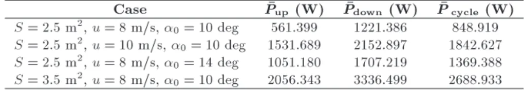
Table 2. The average mechanical power generated by the proposed mechanism under dierent working conditions.
Case Pup (W) Pdown (W) Pcycle (W)
S = 2:5 m2, u = 8 m/s, 0= 10 deg 561.399 1221.386 848.919 S = 2:5 m2, u = 10 m/s, 0= 10 deg 1531.689 2152.897 1842.627 S = 2:5 m2, u = 8 m/s, 0= 14 deg 1051.180 1707.219 1369.388 S = 3:5 m2, u = 8 m/s, 0= 10 deg 2056.343 3336.499 2688.933
Figure 16. The generative power of the lift force in two cases: (a) u = 8 m/s, S = 2:5 m2, and 0= 10 deg, and (b) u = 8 m/s, S = 2:5 m2, and 0= 14 deg.
Figure 17. The generative power of the lift force in two cases: (a) u = 8 m/s, S = 2:5 m2, and 0= 10 deg, and (b) u = 8 m/s, S = 3:5 m2, and 0= 10 deg.
Table 3. Necessary conditions for a fully developed sea for the given wind speed.
Wind condition Wave size
Wind speed in
one direction Fetch
Wind duration
Average height
Average wave length
Average period
5.2 m/s 19 km 2 hr 0.27 m 8.5 m 3 sec
10.2 m/s 139 km 10 hr 1.5 m 33.8 m 5.7 sec
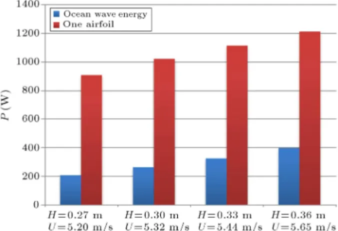
Figure 18. Bar chart of the average power (W) of the mechanism under dierent working conditions.
Figure 19. Comparison of average power (W) predicted based on the proposed mechanism and the wave energy extractor.
setting the parameters of the wind velocity and the projected area u = 8 m/s, S = 2:5 m2 and changing
the angle of attack from 0 = 10 to 0 = 14 lead
to 161% growth in power of the mechanism. Setting parameters u = 8 m/s, and 0 = 10 and changing the
projected area of airfoil from S = 2:5 m2to S = 3:5 m2
lead to 316% increase in power of the mechanism. The results presented in Table 1 and Figure 18 show that the parameter of projected area has greater inuence on the output power than on the wind velocity and angle of attack.
In order to investigate the appropriateness of the proposed mechanism for the extraction of energy
wind, the average mechanical power of the mechanism under u = 5:2 m
s, S = 3:5 m2, and 0 = 14 is
determined for several vertical lengths of stator, such as 2r = 0:3; 0:32; 0:34; 0:36. Similarly, the average power extracted from ocean waves is obtained for the vertical length of stator H = 2r = 0:27; 0:3; 0:33; 0:36 m. The conditions of wind on the surface of ocean given in Table 3 are extracted from Pierson et al. [23].
The obtained results based on the proposed mechanism and ocean wave are given in Table 4 and depicted in a bar chart (Figure 19). It can be observed from Table 4 and the bar chart given in Figure 19 that in spite of the constant vertical length of stator for both methods, the proposed mechanism with one airfoil has relatively good performance in comparison to the ocean waves. It should be noted that power of the proposed mechanism increases by increasing the number of airfoils.
6. Conclusion and future works
In this paper, a new conceptual method for extracting wind energy is introduced. Indeed, the mechanism of this method is the combination of two recent tech-nologies named the ocean wave energy extractor and the linear wind energy. In this method, due to wind velocity, the mover connected to the airfoils undergoes a linear reciprocating motion such that this motion is converted to electricity by using the magnetic eld of a linear generator. The main parts of the mechanism, including a linear generator, a set of airfoils, a ywheel, and the relative motion of these parts were explained. To show the appropriateness of the proposed method, perfect kinematic and kinetic analysis of the mecha-nism, including the displacement, velocity, accelera-tion, force, and mechanical powers, was done. In the kinematic and kinetic analysis, the average generative power predicted based on the proposed method was numerically studied under dierent conditions. Our study shows that parameters such as the wind velocity, the angle of attack, and the projected area of airfoil have the main contribution to the generative power (see Figures 16-18 and Table 2).
In order to evaluate the performance of this method, the mechanical power predicted by the pro-posed method was compared with the output power of the ocean energy extractor in similar situations.
Table 4. A quantitative comparison between the proposed method and ocean wave energy. H or 2r (m) Wave energy (W) 1 airfoil (W) A=W ratio
0.27 m (u = 5:2 m/s) 210.414 908.859 4.319
0.3 m (u = 5:32 m/s) 264.965 1021.147 3.853 0.33 m (u = 5:44 m/s) 328.047 1116.177 3.402 0.36 m (u = 5:65 m/s) 398.633 1211.323 3.038
The comparison of the results shows that the proposed mechanism can generate the mechanical power, which is comparable to the power generated using the ocean energy extractor. Finally, it can be mentioned that the most important advantage of the proposed method in comparison with the two mentioned methods is its simplicity, high eciency, and compatibility with all wind situations.
We believe that the novelty of this work is to introduce the proposed concept analyzed with a simple aerodynamic model in order to give an engineering in-sight into the power output. We have used the simplest aerodynamic theory, Thin Airfoil Theory, because the thin wing theory seems to be an adequate assumption for quick, simple, and accurate ight properties of a wing section. It is very worthwhile to apply a more sophisticated unsteady aerodynamic model including utter and convergence phenomena on our dynamic model. For doing this and in order to achieve a compre-hensive investigation of these complex phenomena, i.e., convergence and utter, it is necessary to study the ow transport, boundary layer (shape factor and thickness), vortex creation, and friction coecient in the boundary layer. Based on this research, the following could be future directions for research on this concept:
1. Study of the vertical distance between airfoils;
2. Investigation of the airfoil motion inuence, es-pecially the eect of uttering and convergence phenomena on CL and CDcoecients;
3. Designing the perfect linear generator which satis-es the boundary conditions;
4. Designing the mechanism with considering top/ down stop point and study of the stress distribution on the whole mechanism to point the critical parts. A well fatigue study on connecting rods is needed for airfoil-carrying structure.
Acknowledgment
We gratefully acknowledge Zarand Power Generation Management Company under management of Mr. Hei-dary for partial support of this work.
References
1. Bouws, E., Gunther, H., Rosenthal, W. and Vincent, C.L. \Similarity of the wind wave spectrum in nite depth water", Spectral form. J. Geophys Res., 90-975-986 (1985).
2. Islam, M., Ting, D.S.K. and Fartaj, A. \Aerodynamic models for Darrieus-type straight-bladed vertical axis wind turbines", Renew. Sust. Energ. Rev., 12, pp. 1087-1109 (2008).
3. Paik, J.K. and Thayamballi, A.K. \Some recent devel-opments on ultimate limit state design technology for
ships and oshore structures", Ship.Oshore Struc., 1, pp. 99-116 (2006).
4. Yeung, R.W., Motley, M.R. and Young, Y.L. \Three-dimensional numerical modeling of the transient uid-structural interaction response of tidal turbines ", J. Oshore. Mech. Arct., 132, pp. 1-12 (2010).
5. El-Tamaly, H.H. and Mohammed, A.A.E. \Impact of interconnection photovoltaic/wind system with utility on their reliability using a fuzzy scheme", Renew. Energ., 31, pp. 2475-2491.
6. Amaris, H., Usaola, J. and Vilar, C. \Assessment of icker limits compliance for wind energy conversion system in the frequency domain", Renew. Energy, 31, pp. 1089-1106 (2006).
7. \Automatic control system and method of the ight prole swing power", Patent n, TO2006A000372, In-ventors: M. Milanese, and M. Ippolito (May 2006).
8. Ippolito, M. \Smart control system exploiting the characteristics of generickites or airfoils to convert energy", European patent # 02840646 (2004).
9. Caldeira, K., Cannon, M., Eccles, D., Roberts, B., Shepard, D. and Grenier, A. \Harnessing high-altitude wind power ", IEEE T. Energy Conver., 22, pp. 136-44. (2007).
10. Argatov, I., Rautakorpi, P. and Silvennoinen, R. \Estimation of the mechanical energyoutput of the kite wind generator", Renew Energy, 34, pp. 1525-1532 (2009).
11. Dominic, D., George, M., Hudson, A. and Shenoi, R.A. \Determination of kite forces using three-dimensional ight trajectories for ship propulsion", Renew. Energ., 36, pp. 2667-2678.
12. Diehl, M., Houska, B. and Ilzho, A. \Nonlinear MPC of kites under varying wind conditions for a new class of large-scale wind power generators", Int. J. Robust Nonlin, 17, pp. 1590-1599 (2007).
13. Wubbo, J. \A novel concept to exploit the energy in the airspace", Aircr. Design, 4, pp. 81-97 (2001).
14. http://www.lineartechnologies.com.au
15. Trilla, L., Bianchi, F.D. and Gomis-Bellmunt, O. \Linear parameter-varying control of permanent mag-net synchronous generators for wind power systems", IET Power Electronics, pp. 692-704 (2014). DOI: 10.1002/rnc.3039.
16. De la Villa Jaen, A., Garca-Santana, A. and Montoya-Andrade, D.E. \Maximizing output power of linear generators for wave energy conversion", Int. Trans. Elec. Energ. Syst. (2013). DOI: 10.1002/etep.1747
17. Darijani, H. and Panahi, A. \Airfoil Linear Wind Generator (ALWG): As a novel wind energy ex-traction approach", International Journal of Recent Advances in Mechanical Engineering (2014). DOI: 10.14810/ijmech.2014.3406
18. Ghita, C., Chirila, A.I., Deaconu, I.D. and Ilina, D.I. \The magnetizing eld of a linear generator used to ob-tain electrical energy from waves energy", ICREPQ'16 (2008).
19. Oskar, D. \Design of a linear generator for wave energy plant", Master Degree project, Uppsala University, (2003).
20. Falc~ao, A.F.O. \Wave energy utilization: a review of the technologies", Renew. Sust. Energ. Rev., 14, pp. 899-918 (2006).
21. Mueller, M. and Wallace, R. \Enabling science and technology for marine renewable energy, energ", Pol-icy, 36, pp. 4376-4382. (2008).
22. Khaligh Alireza, C. and Omer, O. \ Energy harvest-ing", Solar, Wind, Ocean Energy Conversion System, pp. 236-239, Taylor & Francis Group press, United States of America (2010).
23. Pierson, J., Willard, J. and Moskowitz, L.A. \Pro-posed spectral form for fully developed wind seas based on the similarity theory of S. A. Kitaigorodskii", Journal of Geophysical Research, 69, pp. 5181-5190 (1964).
Biographies
Hossein Darijani was born in Bam, Iran, 1980. He received his BSc degree in Solid Mechanics from Shahid Bahonar University of Kerman, Iran, in 2002, his MSc and PhD degrees in Applied Mechanics from Sharif University of Technology, Iran, in 2004, and 2010, respectively. His technical interests are nonlinear continuum mechanics, constitutive modeling of hyper-elastic materials, and renewable energy. Currently, he is Associate Professor in the Department of Mechanical Engineering at Shahid Bahonar University of Kerman, Iran.
Abbas Panahi was born in Shiraz, Iran, 1992. He received his BSc degree in Mechanical Engineering from Shahid Bahonar University of Kerman. Now, he is an MSc student in Aerospace Engineering Department at University of Tehran. His research interests are uid mechanics, renewable energy, and computational nanomechanics (molecular dynamics simulation).