http://www.sciencepublishinggroup.com/j/ajop doi: 10.11648/j.ajop.20170506.11
ISSN: 2330-8486 (Print); ISSN: 2330-8494 (Online)
Using Different Techniques in Data Transferring by
Optisystem Program
Malik A. Jabbar
1, Baraa M. Albaker
1, S. M. Zafar Iqbal
21
Department of Network Engineering, Al-iraqia University, Baghdad, Iraq
2
Khwaja Fareed University of Engineering and Information Technology, Rahim Yar Khan, Pakistan
Email address:
[email protected] (M. A. Jabbar)
To cite this article:
Malik A. Jabbar, Baraa M. Albaker, S. M. Zafar Iqbal. Using Different Techniques in Data Transferring by Optisystem Program. American Journal of Optics and Photonics. Vol. 5, No. 6, 2017, pp. 59-66. doi: 10.11648/j.ajop.20170506.11
Received: February 5, 2017; Accepted: February 27, 2017; Published: December 19, 2017
Abstract:
Nowadays, signal communication is considered as a vital element of our modern daily life. This is due to the need for transmitting large amount of different data types such as text, voice, images, videos, etc. The increase in the volume of data communications requires large data transmission capacity. The data can be transmitted using copper wire, but with low data transmission capacity. To resolve this issue of transmitting large data with a higher signal to noise ratio and larger communication distant, lightwave technology was adopted. The work focuses on the design and the modeling of single and dual channels optical communication systems that use lightwaves as a carrier for signal transmission. This is to study characteristics and conduct performance evaluation and analysis of the designed communication subsystems through the use of different data transmission and reception techniques. Optisystem simulation software is used as a powerful simulation tool in the development of optical system modules, which include the transmitter that converts signal to light, fiber-optic channel, and the receiver that converts light back to the original signal.Keywords:
Fiber Optics, Data Transfer, Optisystem, Lightwave, Optical Communication System1. Introduction
Fiber optics market is currently growing rapidly and its usage turns out to be increasingly popular at local and long wired transmission range. This is owing to its numerous advantages, including: low cost, high transmission bandwidth and zero electromagnetic interferences. Since laser development in 1960s, first optical communication system that relied on a suitable laser optical source was presented. Many researches were conducted next, especially after publishing a paper written by Kao and Hokham [1] that addressed the possibility of signals communication through an optical channel. Optical communication appeared to be difficult to overcome because of attenuation of 1000 dB/km. However, Kao explained that the attenuation was due to fiber impurities.
Further researches in 1970s investigated by Kapron et al. [2] show that through the use of pure silica, the losses could be decreased to 20 dB/km. Corning incorporated titanium doped silica glass for signal transmission with 17dB/Km
constriction and soon the attenuation is decreased to 4dB/Km. Current optical systems have both appropriate optical source and transmission media. The first generation of the optical communication system operates on 0.8µm wavelength and 45Mbit/s with a repeater separation of 10km. The main drawback of this generation was chromatic dispersion (CD) which causes significant pulse broadening, and yields inter-symbol interference (ISI).
systems improvement [4]. Later in 1990, along with the development of low-loss silica fibers and dispersion-shifted fiber (DSF), the third-generation fiber-optic communication system was emerged. Optical system in this generation was characterized by 1.5µm wavelength region with 0.2dB/Km loss and 10Gbit/s with repeater separation limit of 100Km [5].
The evolution of fourth-generation optical communication system started from 1992 until 2001, through the invention of practical optical amplifier, erbium-doped fiber amplifier (EDFA), to replace repeaters and the wavelength-division multiplexing (WDM) method to increase data capacity. Since 1992, several fiber-optic communication systems were developed with bit rate start doubling every six months until a bit rate of 10TB/s was achieved in 2001.
Amemiya, M. in 2002 [6] studied the significant increase in the transmission speed of optical networks. Amemiya showed that the impact of higher order dispersion should be clarified to even and odd higher order dispersion in a single-mode fiber. The transmission limits are analytically obtained for each higher nth order that induces inter symbol interference. Transmission lengths are limited by the factor of 1/B0n, where B0 is the bit rate and n is the dispersion order.
Demir, A. in 2003 [7] discussed the challenges face optical communication systems from design, modeling, and analysis perspective. He presented novel formulations and computational techniques for the analysis of the interplay between the information signals and the optical noise due to the fiber nonlinearity as they propagate together along the fiber link. Finally, he discussed the use of the experimental results in the performance evaluation of communication links, and investigated on system design implications. Chris Xu, Xiang Liu,[8] showed the advantages of DPSK in terms of receiver sensitivity and tolerance to fiber nonlinearity. Ghafour M. and Edmond Z. [9] performed a comparison study among three digital modulation schemes in optical wireless communication systems (OOK, PPM and DPIM).
Shanghai Bin Li. [10] presented the performance analysis of 10Gbps optical receiver for fiber optical link. Non-Return to Zero (NRZ) electrical signals from a Pseudo-Random Bit Sequence (PRBS) Generator are used as modulation input. Effects of bandwidth and thermal noise of receiver on the link performance are studied in detail. Astar W., Jeffrey B., Driscoll et. Al. [11] demonstrated the conversion of 10 Gb/s non-return-to-zero (NRZ) ON-OFF keying NRZ-OOK to RZ-OOK using cross-phase modulation (XPM) in a compact, Silicon (Si) nanowire and a detuned filter.
Xiang Yang and Yang Hechao [13] used the Optisystem software to design and extract simulation results of the fiber optic communications system. Beena R Ballal [14] discussed the disadvantages of analog radio over fiber link. A digitized RF-over-Fiber transmission scheme based on Bandpass Sampling theory is being introduced, Which provides mobility as well as large bandwidth. Comparison of Analog
and digital Radio over Fiber was carried. S.K Mohapatra, R. Bhojray et al, [15], used fiber optic communication channel to transfer data for different analogue and digital techniques, and showed that different digital modulation formats maximizes spectral efficiency and also improves tolerance to transmission impairments.
Preeti V. Murkute, and A. H. Karode [14] studied the coherent communication systems. They discussed the implementation options and design considerations with respect to hardware realization and DSP implementation. N. Alic, E. Myslivets, et. al. [15] investigates the limitations and their origins in the nonlinear effects mitigation in fiber-optic communication systems. The results clearly pointed out to the significant benefits of employing fully frequency referenced carriers in transmission. Alex Alvarado, Erik Agrell [16] showed that the concept of a channel-independent FEC limit is invalid for soft-decision bit-wise decoding. Kazuro Kikuchi [17] explained the role of digital signal processing in mitigating linear transmission impairments, estimating the carrier phase, and tracking the state of polarization of the signal in coherent receivers.
Our work presented in this paper is a part of the previous listed efforts in evaluating and analyzing performance of different lightwave communication systems. The work involves the design and modeling of a single-channel and two-channel optical system using Optisystem software. It also involves studying the effects of utilizing different transmission and reception techniques on the designed models.
2. Lightwave System Design
A lightwave or an optical communication system uses light waves as the carrier for transmitting a signal. The system has three main parts including the transmitter, the receiver and channel. In case of optical communication, transmitters have light sources and receivers have light detectors that are connected to the channels through optical fibers. The transmitter has optical source and modulator. It converts the electrical signal to light. The receiver has an amplifier, detector and filter. It converts the transmitted light back to the voice or music signal to the output. Figure 1 illustrates the processing steps carried out by the designed optical communication system.
Figure 1. Processing steps of data transmission in optical communication system.
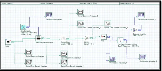
Optisystem program, developed by Optiwave Company, is used here in the design, modeling and performance evaluation of different optical communication systems. It is
considered as a powerful lightwave communication system simulation package that allows us to the design and analysis different optical communication frameworks rapidly and effectively. In addition, the simulator has an effective simulation environment and simulates several real components and communication systems. Figure (2) presents the basic system design of the optical communication system that the modeling, evaluation and analyses were carried out on it. A CW laser is used as a pulse generator to simulate transmitter. A Nonlinear dispersive filer is selected as the channel of communication. A PIN detector, and EDFA amplifier are used at the receiver. An optical spectrum analyzer is deployed to visualize and measure signal spectra.
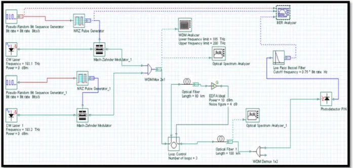
The work involves modeling and simulation of two transmitters. The first is a one-channel transmitter (See Figure (3)). The second is a Two-channel transmitter (See Figure (4)). The simulation setup, as demonstrated in Figure (4), presents the compensation of the FWM. Both transmitters were designed through the utilization of several components provided by the optiwave library.
Figure 2. Basic Communication System Design.
Figure 4. Two-channel optical system simulation setup.
3. Experimental Results
Two different data transmission techniques are modeled and simulated by the optisystem simulator (See Figures (3 and 4)). Twenty experiments were conducted to quantify the data transmission and reception with the two data transmission techniques. A laser optical source of wavelengthes λ=1550, 1330, 850, 650, and 590 was selected to transmit information. The information, at the transmitter side, is modulated with the laser source using Mach-Zehnder modulator. The modulated signal is then transmitted through a single mode optical fiber to the resciever. The transmitted signal along the channel distance will give different results than the transmitter side that monitored by appropriate signals time-frequency visualizers.
At the receiver side, PIN photodiode and Avalanche Photodiode (APD) detectors are used in the extraction of the original transmitted information. RF spectrum analyzers and Time domain visualizers are used in the monitoring, evaluation and analyses of time-frequency characteristics of the transmitted and received information.
3.1. Performance Evaluation
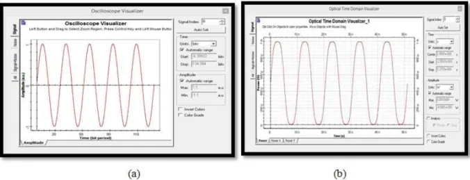
The experiments started by applying a coninuous sinesoidal waveform as an input analogue signal to the optical communication system shown in Figure (3). The signal is monitored by an oscilloscope visualizer and the time-domain signal is depected in Figure(5.a). The input
signal is then modulated by the Mach-Zehnder modulator and the modulated signal is monitored by an optical time-domain visualizer, as shown in Figure (5.b). The resultant signal represents the original continous signal of interest after being carried by the laser signal. This signal is transmitted to the optical channel.
At the receiver subsystem of Figure (3), the signal is detected by the PIN photodiode. Another oscilloscope visualizer is used to monitor the detected received signal. Next, a low pass filter is used to filter out noise and high frequency spectra. Finally, the resultant signal is amlified and monitored by a third oscilloscope visualizer. Figure (6) demonstrates the resultant detected signals at the receiver side. The results show the successful design and modeling of the one-channel lightwave communication system to detect and recover the original transmitted signal.
Figure 5. Time-domain signals at the transmitter side: (a) continuous sine wave input signal (b) The modulated signal after the modulator.
(a) (b)
Figure 6. Time-domain Signals at the receiver side: (a) signal after PIN detector (b) Final received signal.
Figure 8. Corresponding signals spectra at the receiver side for the cases: (a) Digital data (b) Analog signal.
3.2. Characteristics of Modulated Signal
In the third experiment, the input continuous-in-time or discrete-in-time signal, at the transmitter subsystem, was modulated using the CW laser optical source of wavelength λ= 1550nm. Two modulation formats, non-return-to-zero (NRZ) and return-to-zero (RZ), were used by the Mach– Zehnder modulator to study modulated signal characteristics. Figure (9) presents the simulation results of the signal loss measured as a function of variable link ranges. The result shows that RZ is of higher signal loss as compared with NRZ. Therefore, the outcome indicates that NRZ modulation provides better signal recapturing with lower loss than the RZ. This is because of the smaller bandwidth utilization by a factor of two when using NRZ modulator as compared with RZ. The reason behind it is that the ON-OFF transition in RZ modulation occurs more frequently than in RZ modulation.
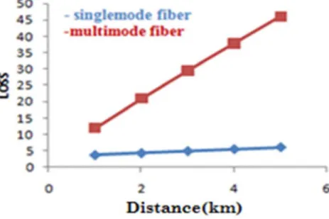
3.3. Effects of the Multimode Fiber Optics
The forth experiment was conducted to measure and analyze the effect of single and multimode fiber optics. The
received signal was measured at different lengths of single and multiple modes fiber optics. The result is depicted in Figure (10). It indicates that the single mode fiber optic performs better than the multimode fiber optic in terms of signal loss, especially at long distances. This is due to small diameter of the single mode fiber optic that will provide lower loss.
3.4. Effects of the Photodetectors
The last experiment was conducted at the receiver side to measure and analyze the effects of using two different photodetectors, PIN and APD. Using RF spectrum after the detector, the simulation results of the two photodetectors were extracted and measured (See Figures (11 and 12)).
The resultant signals indicate that the PIN photodetector performs better than APD counterpart in terms of less noise power accompanied received signal after detection. This is because the PIN photodetector requires less operating power and has lower signal to noise ratio as compared with the random nature of APD photodetector.
Figure 10. Signal loss measurement in single mode and multimode fiber optics.
Figure 11. Power spectra of the detected signal after: (a) PIN photodetector and (b) APD photodetector
4. Conclusions
The use of laser source in lightwave communication systems has better performance than LEDs in terms of higher output power, lower light divergence. It has tighter light outputs and can be easily coupled to single mode fibers. Therefore, it is considered idealistic for high-speed communication links and long distances. For this reason the laser source is deployed in this paper. NRZ modulator performs better than RZ in terms of less sensitive to laser phased noise. In addition, it requires less signal transmission and reception bandwidth by a factor of two as compared to RZ counterpart. Finally, the results show superiority of the PIN photodetector in terms of its effectiveness of use and minimum detection requirements of signal power than the APD photodetector.
References
[1] K. C. Kao and G. A. Hockam, ''Dielectric fiber surface wave guides for optical frequancy,'' proceeding of IEE, vol. 133, pp. 1151-1158, (1996).
[2] Kapron F. P. et. al., ''Maximum Information capacity of Fiber Optic Waveguide,'' IEE Electron Lett., No. 13, pp. 69-76, (1977).
[3] J. I. Yamada, S. Machida and T. Kimura, ''2 Gbit/s optical transmission experiments at 1.3 with 44 km single-mode fibre,'' Electron. Lett. 17, 479 (1981).
[4] Takanori Okoshi, ''Recent Advances in Coherent Optical Fiber Communication Systems,'' Journal of lightwave Technology, Vol. LT-5, No. 1, (1987).
[5] John Wiley & Sons, ''Fiber-Optic Communications Systems'', Third Edition, (2002).
[6] Amemiya, M., ''Pulse Broadening due to Higher Order Dispersion and its Transmission Limit'', Journal of Lightwave Technology, Vol. 20, No. 4, pp. 591-597, (2002).
[7] Demir, A., ''Noise analysis for optical fiber communication systems'', Journal of Lightwave Technology, pp. 441-445, (2003).
[8] Chris Xu & Xiang Liu, ''Differential Phase-Shift Keying for
High Spectral Efficiency Optical Transmissions'' IEEE Journal of Selected Topics In Quantum electronics, Vol. 10, No. 2, (2004).
[9] Xiupu Zhang, and Zhenqian Qu, ''Noise Statistics in Optically Pre-Amplified DPSK Receivers with Optical Mach-Zehnder Interferometer Demodulation'', Optical Society of America, (2005).
[10] Ghafour A. Mahdiraji & Edmond Z., ''Comparison oF Selected Digital Modulation Schemes (OOK, PPM and DPIM) for Wireless Optical Communications'', IEEE Xplore, pp. 5-10, (2006).
[11] Shangai Bin Li., ''BER performance analysis of PIN photodiode in 10Gbps fiber optical communication'', Proceeding of IEEE, PP 1-3, (2006).
[12] W. Astar, Jeffrey B. Driscoll et al, ''Conversion of 10 Gb/s NRZ-OOK to RZ-OOK utilizing XPM in a Si nanowire'', OPTICS EXPRESS, Vol. 17, No. 15, (2009).
[13] Xiang Yang &Yang Hechao, ''The Application of OptiSystem in Optical Fiber Communication Experiments'', Proceedings of the Third International Symposium on Computer Science and Computational Technology, pp. 376-378, (2010).
[14] Beena R B.& Dr. S, ''Performance Comparison of Analog and Digital Radio Over Fiber Link'', International Journal of Computer Science & Engineering Technology (IJCSET), Vol. 3, No. 6, pp. 193-197, (2012).
[15] S. K Mohapatra, R. Bhojray et al, ''Analog and digital modulation formats of optical fiber communication within and beyond 100 GB/S: a comparative overview'', International Journal of Electronics and Communication Engineering & Technology (IJECET), Vol. 4, No. 2, pp. 198-216, (2013). [16] Miss. Preeti V. Murkute, Mr. A. H. Karode, ''Implementation
of Coherent Optical Digital Communication Systems Using Digital Signal Processor & FPGA'', IJEBEA, pp. 89-94, (2014).
[17] N. Alic, E. Myslivets et al, ''Nonlinearity Cancellation in Fiber Optic Links Based on Frequency Referenced Carriers'', Journal of Lightwave Technology, Vol. 32, No. 15, pp. 2690-2677, (2014).