CenterTrack: An IP Overlay Network for Tracking DoS Floods
Robert Stone
UUNET Technologies, Inc.
[email protected]Abstract
Finding the source of forged Internet Protocol (IP) datagrams in a large, high-speed network is diffi-cult due to the design of the IP protocol and the lack of sufficient capability in most speed, high-capacity router implementations. Typically, not enough of the routers in such a network are capa-ble of performing the packet forwarding diagnostics required for this. As a result, tracking-down the source of a flood-type denial-of-service (DoS) attack is usually difficult or impossible in these networks. CenterTrack is an overlay network, consisting of IP tunnels or other connections, that is used to selec-tively reroute interesting datagrams directly from edge routers to special tracking routers. The track-ing routers, or associated sniffers, can easily de-termine the ingress edge router by observing from which tunnel the datagrams arrive. The datagrams can be examined, then dropped or forwarded to the appropriate egress point.
This system simplifies the work required to deter-mine the ingress adjacency of a flood attack while bypassing any equipment which may be incapable of performing the necessary diagnostic functions.
1
Introduction
While the Internet Protocol is simple and effective, it lacks an obvious way to ensure that the address contained in the source address field of each packet is actually representative of where the packet origi-nated [1]. IP alone does not address this security is-sue. Consequently, an attacker can forge the source address of an IP packet from any site on the Internet which is not subject to some sort of source valida-tion mechanism. Examples of such mechanisms are egress filtering (by the originating site) and ingress
filtering (by the backbone provider) [2]. As of the time of this writing, source address validation is not yet in general practice on the Internet.
Furthermore, there are no quality-of-service or re-source restriction mechanisms that are practical or in general use that prohibit an attacker from suming all available bandwidth on a network con-nection.1 Due to their trivial nature, packet flood attacks are not only possible, but they have become quite common.
A flood attack differs from other types of DoS at-tacks in that it requires constant and rapid trans-mission of packets to the victim in order to be ef-fective. Some DoS attacks, such as the “ping of death” [3] and similar attacks, merely require that a single “killer packet” reach the victim. This pa-per addresses the issue of tracking (tracing)flowsof forged packets rather than individual forged pack-ets. Tracking individual forged packets is generally infeasible and thus other methods, such as patching vulnerable systems, are commonly used to protect against the killer packet class of attacks.
Internet Service Providers (ISPs) and their cus-tomers are frequently the victims of various types of packet flood attacks. Included in the category of packet flood attacks are “Smurf” [4], “Fraggle” [5], TCP SYN Flood [6], and others. Not only is it possible for the attacker to arbitrarily alter the source address field of the attack packets without penalty, many of these attacks actually require that the source address be faked in order to be effective. Because the source address field is almost always forged in these attacks, it is non-trivial to determine their true origin. Often, the packet forwarding di-agnostic functions necessary to determine the true source of the attack are not available due to
hard-1Even if there were, the lack of validation of the IP headers
would probably allow an attacker to bypass such mechanisms by forging packets which would appear to conform to the network usage policy.
ware resource limitations or software implementa-tions which lack the appropriate features.
As if the situation could not possibly get any worse, the amazing success of the Internet has increased the number of Internet hosts which are vulnerable to unauthorized access. This condition makes dis-tributed denial-of-service (DDoS) attacks [7] more feasible than they might have been at one time. In effect, attackers cannot only hide their identity and exploit amplification methods, but also increase the number of hosts used in an attack from a single host to hundreds or thousands of hosts.
This paper presents several different approaches to the problem of tracing the ingress adjacency of rea-sonably large flows of forged IP packets. It then details a specific solution based on IP tunnels (such as GRE) [8, 9], Border Gateway Protocol (BGP) [10, 11, 12], an Interior Gateway Protocol (IGP) such as Open Systems Interconnect Intermediate System to Intermediate System (IS-IS) [11, 13, 14], and diagnostic features on a subset of routers in the network backbone. Lastly, the benefits and limita-tions of the method are discussed along with the ap-plicability to DDoS attacks. Methods of preventing such attacks, through source validation for example, are not discussed in this document.
2
Assumptions and
Definitions
If two routers are physically or virtually connected and this connection is used to exachange IP packets, then the two routers are considered to be adjacent. The connection between the two routers is referred to as an adjacency. Adjacency capacity refers to a router’s capacity to handle all of the required con-nections, routing sessions, bandwidth, and anything else needed to maintain a certain number of adja-cencies.
In the examples, it is assumed that we are track-ing attacks across a hypothetical ISP backbone net-work. There are two basic classifications of routers used: backbone routers and external routers. Back-bone routersare routers which are part of the ISP backbone network. External routers are routers which are not part of the ISP backbone network; they could belong to a customer or another ISP.
Backbone routers are sub-classified by what they are adjacent to. Edge routersare backbone routers that are adjacent to one or more external routers. Transit routersare backbone routers which are only adjacent to other backbone routers.
In addition to these routers, we will present a special case of router called atracking routerwhich is con-ceptually adjacent only to edge routers and other tracking routers. An adjacency between a tracking router and an edge router, or a tracking router and another tracking router, is called a tracking adja-cency.
Because the example network is an ISP network, it is assumed that attacks originate outside of the net-work and that they are targeted at a victim outside of the network. Therefore, the malicious packets that comprise the attack will be transmitted across the edge of the network twice: once at the ingress edge adjacency(the source of the attack), and once at theegress edge adjacency(the destination of the attack), whereedge adjacencyrefers to an adjacency between an edge router and an external router. The ingress edge routeris therefore the edge router which has the ingress edge adjacency, and conversely the egress edge routeris the edge router which has the egress edge adjacency.
Attack signature refers to some pattern which can be used to help distinguish malicious packets from normal traffic. At the very least, an attack signature is defined by the IP address or address range of the entity that is being attacked. Often it is not possible to determine an attack signature that only matches malicious packets. A good attack signature will pre-dominantly match malicious packets but may also match a certain amount of legitimate traffic. Input debuggingrefers to the diagnostic features re-quired to determine from which adjacency a packet matching an attack signature on an individual router arrived. In other words, input debugging is any feature that will reveal which previous hop the attack is coming from or through.
Atracking hopis one invocation of input debugging on a particular router. It could also be described as the act of querying a specific router for input de-bugging information matching a particular attack signature. The number of tracking hops is often referred to in terms ofdor dtwhere dis the maxi-mum hop diameter of the backbone network anddt is the hop diameter of the CenterTrack overlay
net-work. There is no fixed relationship betweendand dtsince either network could be of an arbitrary hop diameter, butdt< dfor any useful implementation of CenterTrack.
3
Finding a Solution
3.1
Possible Solutions
We originally considered several possible solutions to the problem of tracking forged packets. Several of the ideas that were given consideration are sum-marized below.
• Hop-by-hop: This is the method used by the DoSTrack2 script. Input debugging is per-formed on the edge router closest to the victim in order to determine which adjacency on that router originated the attack packets. Once the adjacency is identified, the process is repeated on that adjacent router. This method is ap-plied recursively until the edge of the network is reached and the edge ingress adjacency is iden-tified. This requires up todtracking hops.
• Hop-by-hop from center: Traffic for the victim is rerouted to a router at the top level of the network (effectively in the “center” with regard to hop diameter) and then discarded. That router effectively becomes the victim, and hop-by-hop tracking is performed starting with that router. This requires at most d/2 + 1 hops. Though it is theoretically unnecessary to dis-card the traffic in order to perform the diag-nostics, it is usually non-trivial or impossible to route the traffic through a particular router and out of the network through the egress ad-jacency.
• Hop-by-hop through overlay network: This is the method employed by CenterTrack. An overlay network is created which links all edge routers to a central tracking router or a simple network of tracking routers. Dynamic routing is employed which causes only the traffic des-tined for the victim to be routed through the
2DoSTrack is a Cisco-specific perl script that implements
this method. The last official version would not work on any routers configured to use Cisco Express Forwarding, which includes most Cisco routers used by large ISPs today. It is no longer officially distributed or supported by its authors.
overlay network. Hop-by-hop tracking is then used, starting with the tracking router closest to the victim. This requires up todt+ 1 track-ing hops.
• Traffic flow measurement3on edge adjacencies: All edge routers provide some level of traffic flow measurement data on all edge adjacen-cies. This data must contain, at a minimum, source address, destination address, adjacency, and approximate number of packets. This data is then searched, based on the attack signature, to determine the ingress adjacency of the at-tack. This requires no tracking hops per se, but it does require a (potentially very large) database search.
Additional areas of research were suggested by other researchers after the original consideration of the problem at UUNET. Two of the more promising ideas, packet marking [15, 16] and ICMP traceback generation [17], are similar to logging traffic flow in-formation except that only a small percentage of the traffic is sampled and traffic flow path information is transmitted to the flow destination instead of a system managed by the network operator. These solutions require significant new protocol develop-ment and, while they would provide solutions that are superior to the one discussed in this paper, they are oriented toward a longer-term horizon. A good comparison of various proposals is provided in [16].
3.2
Advantages and
Disadvantages
A brief summary of the advantages and disadvan-tages of each method presented above is described below.
• Hop-by-hop: This method is transparent to the victim and attacker since interrupting the flow of legitimate traffic and alterations to rout-ing are typically unnecessary. This method re-quires input debugging features on every router
3See [18] for more information on Traffic Flow
Measure-ment. We are assuming a relatively simple static rule set for this comparison. For an example of a traffic flow measure-ment system, see the documeasure-mentation on cflowd [19].
Others are investigating methods which require the con-figuration of generalized attack signatures on the monitoring systems to reduce the amount of data that is generated and provide for the possibility of active enforcement [20, 21, 22].
in the network. Even if the software functions exist, the hardware resources may not exist es-pecially on multi-gigabit routers operating at full capacity. There are currently no standards for input debugging. This method does not scale well to DDoS attacks due to the large number of operations required.
• Hop-by-hop from center: The primary advan-tage is that the number of hops required to complete the process is reduced by about 1/2 over the previous method. Otherwise, this method suffers from the same limitations as the previous method. In addition, legitimate traffic usually must be discarded along with the mali-cious traffic, and routing changes are required.
• Hop-by-hop through overlay network (Center-Track): With this method, specialized diag-nostic features are now required only on edge routers and special-purpose tracking routers. Heavily-loaded high-speed transit routers no longer require such features. Also, the number of hops required to perform tracking is typi-cally reduced to 2 or 3. Because this method requires that an overlay network be created, it increases the complexity of the network and in-troduces additional administration tasks. Re-quired routing changes may have a global im-pact on the network if not performed properly; this introduces greater operational risk. While this method is better suited to DDoS attacks than plain hop-by-hop (in terms of number of operations) it is still not ideal. The additional overhead of encapsulating packets is incurred on a larger number of edge routers when used to route a DDoS attack, increasing the poten-tial for collateral damage.
• Traffic flow measurement on edge adjacencies: No network configuration or rerouting is re-quired in order to track malicious flows of traf-fic; the collected information is simply searched based on the attack signature. Also, because the data are retained for some period of time, the source of an attack can be determined after it has already stopped. All edge routers must be capable of performing the required account-ing function, and (in the absence of a manage-able, scalmanage-able, dynamic configuration method) this function must be performed by all of the edge routers all of the time. The accounting functions generate a tremendous amount of in-formation which consumes network bandwidth. The data must be collected at one location or a
small, manageable number of locations in order to be searched effectively. This method does, however, have the best scaling properties with respect to DDoS attacks.
3.3
Design Goals
In choosing and designing a system, the following requirements were taken into account:
• Must be able to identify the source adjacency of the vast majority of DoS floods without in-terrupting the flow of legitimate traffic.
• Must be as vendor independent as possible, us-ing standard protocols (such as BGP, GRE, etc.) where possible.
• Must utilize existing products or products that will be available in the near future (several months).
• Should limit the number and complexity of fea-tures required on transit routers.
• Should introduce as little additional network complexity as possible.
• Should introduce minimal additional opera-tional risk to the backbone.
• The tracking process should be fast and consist of few individual configuration operations.
• Cost and deployment time should be minimal. It is worth noting that moderate or large scale (more than 10 distributed attackers) DDoS attacks were not a concern when we originally determined our requirements. As a result, scalability to DDoS at-tacks was not a design goal for this system.
3.4
Other Factors Considered
In addition to the design goals, a number of factors were taken into consideration when deciding which solution to pursue. A few of them are mentioned below.
• Router vendors often do not implement the required software functionality for hop-by-hop
tracking or traffic flow measurement, particu-larly on multi-gigabit platforms.
• Router vendors typically do not design routers with the necessary resources for packet tracking diagnostic and accounting functions; routers are designed to forward packets rather than an-alyze them. This is particularly true of the highest-end routers.
• Currently it is impossible in most IP network routing architectures to force traffic for a par-ticular destination through an arbitrary transit router using dynamic routing protocols.
• Dynamic routing processes are often suscep-tible to being disrupted with unintended an-nouncements or other data which can severely disrupt a network.
• Traffic flow measurement, especially in large networks, typically generates a massive amount of data which is difficult to store and search, quires a massive configuration operation, or re-quires intelligent meters that can dynamically configure themselves.
3.5
The CenterTrack Decision
We have concluded that the two most promising methods are hop-by-hop tracking through an over-lay network and traffic flow measurement. Because the functionality required for hop-by-hop tracking through an overlay network is more readily available and practical in a large network within the desired time frame, we decided to consider that approach first.
4
CenterTrack Design Issues
We have designed a model for an overlay network that we call “CenterTrack,” as well as a specific method of implementing it. This model calls for a central tracking system that is built “virtually ad-jacent” to all edge routers. Edge routers, as well as the equipment that comprises the tracking system, must be able to perform input debugging. A few of the design issues are presented below.
4.1
Tracking Adjacencies
The tracking system must be adjacent to all edge equipment. This can be accomplished using physi-cal connections, layer 2 virtual connections (VCs), or IP tunnels. Physical connections are very cost-prohibitive. Layer 2 VCs are dependent on a par-ticular contiguous layer 2 technology, such as ATM or Frame Relay, which must be accessible by both the tracking system and the edge routers. Design changes which alter the network over which VCs are built may require a rebuild of the tracking network. IP tunnels can always be built over the existing IP network. Because IP is available to all edge routers, and is not likely to be eliminated from the design of an ISP backbone network, the tunnels can survive underlying network changes. This reduces the num-ber of problems inherent in managing the tracking network.
4.2
Routing Architecture
In order to be practical and effective, some system of dynamic routing must exist between the edge equip-ment and the tracking system. The system depends on ease of routing updates to edge equipment in or-der to pinpoint the desired edge router.
At the same time, however, the ability of the overlay network to disrupt normal routing must be reduced as much as possible. A poor implementation could make it too easy for a small error to severely disrupt the network.
An Interior Gateway Protocol, such as IS-IS or OSPF [11, 23], could be used to handle dynamic routing updates between the tracking system and the edge routers, but this would require that the tracking network be treated as an integral part of the backbone network. The lack of administrative distinction between the tracking network and the backbone network would pose a risk to normal op-eration.
Less risk is involved if a strong administrative dis-tinction exists between the overlay network and the real network. IGPs typically do not allow as much administrative distinction to be made between dif-ferent parts of the network. Because of this, we decided that designing the network as an external
autonomous system using BGP to handle routing updates would pose less risk while accomplishing the same result.
4.3
Scalability Issues
4.3.1 Single Tracking Router
In a small implementation, the tracking system would consist of a single router with tunnels con-necting it to all edge routers. If the number of edge routers is larger than the number of tracking ad-jacencies serviceable from a single router, multiple routers are necessary.
4.3.2 Single-Level Full Mesh
If we haveNCtracking routers that can each handle C tracking adjacencies then we haveCNC tracking adjacencies available. Since the number of edges required to fully mesh all nodes in an undirected graph isNC(NC−1)/2, the same number of adjacen-cies are required to fully mesh all tracking routers. Therefore, this leaves
NE= CNC− NC(NC−1) 2
NE tracking adjacencies available for use by edge routers. Using the quadratic formula to solve for NC we find that, NC= & (C+1 2)− r (C+1 2) 2−2N E '
for a single level full mesh network of tracking routers, if each tracking router can handleC track-ing adjacencies. This means that diminishtrack-ing re-turns are observed when adding additional track-ing routers until the number of tracktrack-ing routers reaches a maximum of d(C−1)/2e. After that point, adding additional tracking routers actually reduces the number of available tracking adjacen-cies for edge routers.
0 50 100 150 200 250 300 0 500 1000 1500 2000 2500
Adjacency Capacity of CT Routers (C)
Serviceable Edge Routers (NE)
Number of CT Routers (NC)
10 20 30
Figure 1: This graph shows how single-level full mesh CenterTrack networks composed of 10, 20, and 30 routers (NC) scale in terms of edge routers (NE) with respect to individual tracking router capacity (C).
4.3.3 Two-Level Hierarchy
If we take the full mesh of adjacencies between tracking routers and replace it with a set of adjacen-cies to a second-level “hub” tracking router, we now have a two-level hierarchy with one router at the top level. In this sort of network,NC(NC−1)/2 adja-cencies between tracking routers and other tracking routers are replaced withNC−1 adjacencies to a sin-gle CenterTrack transit router. This increases the diameter of the CenterTrack network by an addi-tional hop, frees-upNC(NC−1)/2−(NC−1) adja-cencies, requires another router, and does not result in much additional edge router capacity(NE) if NC is a small percentage of C. If NC is at its single-level full-mesh maximum ofd(C−1)/2e, then mov-ing to this topology effectively doubles the number of tracking adjacencies available for edge routers. In addition, it doubles the maximum possible number of tracking routers. (Achieving maximum capacity requires approximatelyC/2 routers in a single-level full mesh and approximatelyCrouters in a two-level hierarchy.) Figure 2 provides a comparison. Due to the additional hop introduced, the poor dis-tribution of workload, and the introduction of a sin-gle point of failure with this design, it is more desir-able to use a single full mesh with a small number of tracking routers that can each handle a large num-ber of tracking adjacencies. The two-level topol-ogy is usually only worth considering if the network
0 1000 2000 3000 4000 5000 6000 7000 8000 9000 10000 10 20 30 40 50 60 70 80 90 100
Maximum Serviceable Edge Routers (N
E
)
Adjacency Capacity of CT Routers (C) Single-Level
Two-Level
Figure 2: Maximum scalability comparison of dif-ferent topologies given tracking routers with a ca-pacity ofC. This represents the absolute maximum number of edge routers that could be supported.
grows faster than router capacity and NC is reach-ing its limit.
4.4
Tracking Router Capabilities
Tracking routers must be able to perform input de-bugging. They must also be able to handle sufficient tracking adjacencies (using IP tunnels) such that adjacencies can be built between the CenterTrack system and all edge routers without requiring more than a manageable number of tracking routers. Assuming that you want to manage no more than NC tracking routers, and you have (or expect to have) NE edge routers, each tracking router must have a tracking adjacency capacity of:
C= N C−1 2 + NE NC
4.5
Edge Router Capabilities
Edge routers also must support input debugging and some acceptable method of IP-over-IP tunnel-ing. Unlike the tracking routers, each edge router is only required to maintain one tunnel.
Level 1 Mesh (XR) Level 1 Mesh (XR) Level 2 Mesh (TR) Tracking Router (CT) Network Transit Backbone Edge (GW) CenterTrack "Backbone" Tunnel Adjacency Physical Adjacency
Figure 3: Conceptualized network diagram with two-level backbone.
5
Implementation
5.1
Example Network
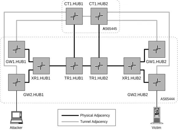
The test lab network in Figure 4 is a gross sim-plification of the current UUNET backbone design. In this network, the “CT” routers are the Center-Track routers (also referred to as tracking routers) the “TR” and “XR” routers are transit routers, and the “GW” routers are edge routers. The TR routers represent the top level in the transit router hierar-chy, and the XRs represent the bottom level. (In a full-scale network, the two TR routers would be a larger full mesh of TR routers and each XR router would be replaced with a regional full mesh of XR routers. See Figure 3.) The CT routers are physi-cally connected at the top level.
An IP tunnel exists between the two CT routers, creating the simplest instance of a full mesh. IP tun-nels exist between the CT router in each hub/region and the GW routers in each hub/region. In this way, all edge routers are reachable from each other through the overlay network created by the CT routers.
In BGP routing terms, the backbone routers are in AS 65444, while CT routers are in a separate AS, 65445.
AS65445 AS65444 Tunnel Adjacency Physical Adjacency CT1.HUB1 CT1.HUB2 GW1.HUB1 GW2.HUB1
XR1.HUB1 TR1.HUB1 TR1.HUB2 XR1.HUB2
GW2.HUB2
GW1.HUB2
Attacker Victim
Figure 4: Test Lab Network. This is an extremely simplified version of the UUNET North America back-bone. A much larger mesh of TR routers and several separate meshes of XR routers exist in the actual backbone.
5.2
Dynamic Routing With Tunnels
If a router determines, usually due to a routing announcement, that a tunnel’s endpoint address is reachable through the tunnel itself, then the tun-nel becomes useless. This problem is calledtunnel collapse. In order to keep this from happening, it is necessary to ensure that no tunnel endpoint ad-dress can be announced as being reachable through a tunnel. The easiest way to do this is to number tunnel termination interfaces out of a distinct range of addresses called the tunnel termination address space, and use this range to filter the routing an-nouncements. In IP terms, the tunnel termination addresses would be used in the outer IP header of a tunnel packet.
In addition, we do not want traffic that should be using the overlay network to be routed directly out of a tracking router’s physical interface without be-ing encapsulated. For this reason, tunnel interfaces should be numbered out of a distinct address range,
called thetunnel interface address space. (The least-specific, i.e. shortest, prefix for this block should be routed to a discard next-hop to prevent matching a default route.)
With these address ranges defined, the rules can be summarized as follows:
• Tunnel interfaces never announce or accept prefixes from the tunnel termination address space.
• The tracking router’s physical interfaces never announce or accept prefixes that are part of the tunnel interface address space.
Configuring the route announcement filtering in this manner will prevent tunnels from collapsing, and will ensure that packets intended to transit the over-lay network will not bypass it.
5.3
Tracking Router
Physical Connection
Each tracking router must be physically connected to the backbone. It is possible to accomplish the routing part of this with static routing, or EBGP if desired.
In both cases, a primary loopback address is cre-ated on the tracking router to serve as an endpoint for tunnels. The primary loopback address must be numbered out of the tunnel termination address space. Also, in both cases, the prefix for the entire tunnel interface address space is routed to a discard next-hop. This is so that any packets destined for an unknown address in that range will not match the default route and be forwarded out of the physical adjacency.
5.3.1 Static Routing
When static routing is employed, the tracking routers have a default route to the backbone through their physical adjacency. The primary loop-back is statically routed to the tracking router from the adjacent backbone router.
5.3.2 BGP Routing
If used, BGP should only announce the primary loopback of the tracking router. Only a default route is announced to the tracking router from the backbone.
5.4
Tunnel Termination
Once the tracking routers are physically connected to the network and their primary loopbacks are reachable from the backbone, it becomes possible to create the tunnels. The primary loopbacks of the tracking routers are used as the termination in-terfaces for tunnels. While physical interface ad-dresses could be used, using the primary loopback interfaces allows for more flexibility with physical interface numbering.
5.5
Tunnel Numbering Methods
On most router implementations, tunnels can be numbered or unnumbered. Using the numbered method, /30 blocks out of the tunnel interface ad-dress space are assigned to each tunnel. This causes each tunnel interface to have a different IP ad-dress. Using the unnumbered method, a special-purpose secondary loopback interface is created on each router that will terminate a tunnel. This over-lay loopback is numbered from the tunnel interface address space. Rather than numbering the tunnels themselves, the routers learn or are configured to know what overlay loopback is reachable through each tunnel.
The numbered method uses more address space and requires approximately as much configuration as the unnumbered method. The unnumbered method uses less address space and is easier to manage be-cause each router only has one next-hop IP address rather than one for every tunnel that terminates on the router. We will assume that the unnumbered method is being used.
5.6
Tracking System IGP and IBGP
Once tunnels have been built such that all of the tracking routers are fully meshed over tunnels, an IGP4 should be used to distribute link-state infor-mation about the tunnels and establish reachability information for the tracking system’s overlay loop-back interfaces. The IGP should only advertise the overlay loopback addresses. In particular, if the pri-mary loopbacks are advertised then tunnels will col-lapse.
Because EBGP will be used by all tracking routers to announce routes to the edge routers, all track-ing routers must have IBGP sessions established with each other. Filters must be applied to prevent the primary loopback addresses from being learned through IBGP. If filters are not applied, then the tunnels will collapse.
5.7
Edge Tunnels
Edge tunnels between the edge routers and the tracking routers are built in the same manner as the internal tunnels used to mesh the tracking routers together. An overlay loopback is created on each edge router, and a static route for the tracking router overlay loopback is added to establish reach-ability of the tracking router through the tunnel. Similarly, a static route is added on the tracking router which establishes reachability of the edge router’s overlay loopback through the tunnel. In this manner, connectivity is established which can be used to establish an EBGP session.
The static routes were unnecessary on the internal tunnels because an IGP was being used. An IGP is not used with the edge routers to avoid conflict with the backbone IGP.
5.8
Edge Tunnel EBGP Sessions
EBGP is configured, using the overlay loopback ad-dresses, between each edge router and the corre-sponding tracking router. The following filters are used:
1. The edge routers are configured:
(a) to accept all prefixes from the tracking system that are not within the tunnel ter-mination address space.
(b) to set the BGP local-preference attribute high so that the additional AS hop in-troduced into the path will not cause the route to be ignored in favor of a competing route with the same prefix length. (c) not to announce any prefixes to the
track-ing system.
2. The tracking routers are configured:
(a) to ignore all prefixes originating from any edge routers.
(b) to only advertise local prefixes (except those in the tunnel termination address space) to the edge routers.
6
Usage
6.1
Static Routes
To use CenterTrack, the packets to be tracked must be flowing over the CenterTrack network. To accom-plish this, static routes are added on two routers.
• A static route5for the victim, pointing through the egress edge adjacency, is added on the egress edge router. This ensures that a more specific route learned from CenterTrack will not take precedence over the normal egress path.
• A static route for the victim, pointing through the tunnel to the egress edge router, is added on the tracking router adjacent to the egress edge router. This route is announced via IBGP to the other tracking routers, and then announced to all edge routers via EBGP.
Once routing converges, all6 traffic for the victim will take a path through the overlay network. It is important that all traffic continue to be routed to the victim because the victim generally still wants to receive legitimate traffic. Due to limitations of most IP forwarding implementations and dynamic routing protocols, it is not possible to only reroute the traffic matching a complex attack signature. Therefore all traffic for a victim must be rerouted through the overlay network, and all the complex pattern matching against an attack signature must be done in the input debugging process. Filters might also be placed on the tracking routers to deny passage to the attack packets if the edge routers are unable to perform the required filtering.
6.2
Hop-by-Hop Tracking
Once traffic has been rerouted, it is possible to em-ploy hop-by-hop tracking to find the source of the attack. The process for tracking an attack from a single source is described below. (This paper does
5Arbitrary length prefix, usually a host route.
6Well, not quite. Traffic entering the network at the egress
edge router will never be transmitted across the CenterTrack network. In other words, if the egress router is also the ingress router then the traffic will never be routed over the overlay network.
not address issues related to automating this pro-cess in software.)
1. The initial starting point is the tracking router closest to the victim.
2. Input debugging is performed on the current router.
(a) If no attack is seen from any of the tunnels, then the attack must be originating from something (another customer or peer) ad-jacent to the egress edge router. Input debugging is then performed on the egress edge router to find the source. The pro-cess ends.
(b) If an adjacency is identified as the source of the attack, then
i. If the adjacency connects to a back-bone router or tracking router, repeat step 2 on the corresponding router. (This router becomes the “current router.”)
ii. If the adjacency connects to an exter-nal router, we have found the ingress adjacency and the process ends. Fil-ters can be applied, the attacking site contacted, etc.
An attack from multiple sources can also be tracked using this method; where multiple source adjacen-cies are identified, each one must be investigated separately (possibly in parallel) until multiple edge adjacencies are identified. This capability is useful since multiple source attacks are quite common; at-tackers often “team up” to tackle a single victim, es-sentially creating a small-scale “manual” DDoS at-tack. However, this method is not scalable with re-gards to DDoS attacks in general unless the method is highly automated.
6.3
Packet Capture
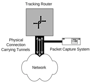
Full packet capture can be useful for analyzing a new attack in detail and recording evidence of an attack for use in prosecution. Even though most routers are not capable of full packet capture, it is still pos-sible to use this system to help “sniff” most traffic, for a specific destination, that enters the backbone. This could be accomplished by using systems capa-ble of full packet capture as the tracking routers,
Tracking Router
Packet Capture System
Network Physical
Connection Carrying Tunnels
Figure 5: Using a sniffer in conjunction with a track-ing router. This would be useful when the tracktrack-ing router cannot perform all of the desired traffic anal-ysis functions.
or by attaching specialized sniffers on the physical connections between the tracking routers and the backbone, as show in Figure 5. It cannot be guar-anteed that all traffic for a given destination can be sniffed in this manner because, if the source and destination are connected to the same edge router, traffic will not transit the tracking network. Aside from packet capture, a separate system could also be used to perform the input debugging func-tion if, for example, a particular tracking router is desirable for its ability to perform IP encapsulation but lacking in diagnostic functions. Effectively this would distribute the tracking router functionality between two machines.
7
Problems and Limitations
7.1
Attacks from Within
This system is not very useful for tracking attacks that originate from within the backbone itself. How-ever, an attack that originates from a transit router that is directly connected to an edge router is equiv-alent to an attack that originates from outside of
the backbone, and it can be tracked just as easily. This system does not simplify the process of track-ing attacks originattrack-ing from within the backbone and more than one hop away from an edge router.
7.2
Attacks on Backbone Routers
It is difficult or impossible to use this system to help track an attack in which a backbone router is a victim. Attempting to reroute traffic destined to a backbone router interface over the tracking network would cause tunnel collapse or routing loops.
7.3
“Stepping Stone” Routers
An attacker can bypass the overlay network by “bouncing” the attack off of one of the transit routers. For example, an attacker sends ICMP echo request packets to TR1.HUB1 and forges the source address as the address of a victim.
7.4
Tunnel Overhead
Assuming the attacker were to use the smallest pos-sible IP packet with a 20 byte header and an empty payload, the additional IP header used to encap-sulate the packet would increase the packet size by over 100%. Though the bandwidth consumed by the attack at the edge adjacency would not be affected, this would effectively double the bandwidth utiliza-tion of the attack as it transited the backbone in encapsulated form. Therefore, the overlay network can be exploited to amplify the effects of the DoS attack on the backbone itself.
One possible solution to this is some sort of asym-metric load sharing of the rerouted flow between the overlay network and the physical backbone. This might allow, for example, 10% of the desired packet flow to be transmitted over the CenterTrack net-work while the rest is transmitted normally over the backbone. We have not yet thoroughly investigated methods for accomplishing this.
7.5
Tunnel Authentication
If the tunnels are not authenticated in some way, attackers can exploit the overlay network to further conceal the source of their attack. With some eas-ily guessable knowledge of the tunnel endpoints, the tunnel packets themselves can be forged, effectively inserting arbitrary packets into a tunnel from afar. While some weak authentication features of GRE might help with this, they have been removed from the latest version of the RFC [8, 9] and are unim-plemented in many newer routers. Using the IPSEC authentication header in tunnel mode [24, 25] pro-vides a solution to this problem, but IPSEC is not widely implemented on general purpose high-capacity IP routing equipment at the current time. Using layer 2 VCs can also solve this problem, but such connections suffer from previously stated dis-advantages.
7.6
Visibility
Because all traffic to the victim is rerouted over an unusual path, the attacker could detect that the sys-tem is being used by using traceroute or a similar tool. This visibility can be limited by configuring the tracking routers in some manner so that they will not send ICMP TTL Exceeded messages. If this is done, the attacker may notice that something has changed, but will have less information about ex-actly what is going on. It is also possible to have the tracking routers respond with bogus TTL Ex-ceeded messages in order to misrepresent the actual network path.
7.7
Distributed DoS Attacks
It is not obvious how scalable this approach is with regards to large DDoS attacks. The number of op-erations required to track-down all of the ingress points is slightly larger than the number of ingress points, which could be very large. Also, the over-head of tunnel encapsulation could dangerously am-plify the effects of a DDoS attack on the network backbone.
8
Conclusions
The hop-by-hop tracking method employing input debugging is basically sound. However, a simplified tracking network connecting all edge routers via a small number of hops provides an optimized envi-ronment for using hop-by-hop tracking. Further-more, building the tracking network as an overlay network, using IP tunnels, allows the tracking net-work to survive changes to the backbone architec-ture at a minimal cost of increased complexity and bandwidth usage.
While a single tracking router may be sufficient for small networks, a single level fully-meshed network of tracking routers is required for large ISP back-bones. A two-level system can be used, but the ex-tra hop that is introduced generally outweighs the scaling benefits.
In addition to tracking forged packets, the system can be used for full packet capture provided that the necessary capabilities exist at the tracking routers. This is useful for detailed analysis of attacks. There are a number of weaknesses in the system which limit its applicability and effectiveness in many situations. However, many of these problems have yet to be overcome in practice. More work is needed to determine the usefulness of this approach.
9
Experiences
CenterTrack has been successful in lab testing but has not yet been implemented in production. We are planning to deploy such a system at some point in the future, however.
10
Acknowledgments
This work was funded by UUNET Technologies, Inc. The author wishes to thank Matthew Sibley for the original idea, and Mark Krause for sup-porting the effort. Contributions by the following people were greatly appreciated: Eric Brandwine, Clarissa Cook, Ken Dahl, Todd MacDermid, Vijay Gill, Keith Howell, Robert Noland.
References
[1] Steven M. Bellovin. Security Problems in the TCP/IP Protocol Suite. Computer Communi-cations Review, 9(2):32-48, April 1989. [2] P. Ferguson and D. Senie. Network Ingress
Fil-tering: Defeating Denial of Service Attacks Which Employ IP Source Address Spoofing. RFC 2267, January 1998.
[3] Computer Emergency Response Team. CERT Advisory CA-96.26: Denial-of-Service Attack via pings. http://www.cert.org/advisories/CA-96.26.ping.html, December 1996.
[4] Computer Emergency Response
Team. CERT Advisory CA-98.01:
”smurf” IP Denial-of-Service Attacks.
http://www.cert.org/advisories/CA-98.01.smurf.html, January, 1998.
[5] Craig A. Huegen. The Latest in De-nial of Service Attacks: “Smurfing.” http://users.quadrunner.com/chuegen/smurf.cgi. February, 2000.
[6] Computer Emergency Response Team. CERT Advisory CA-96.21: TCP SYN Flooding and IP Spoofing Attacks.
http://www.cert.org/advisories/CA-96.21.tcp syn flooding.html. August, 1998.
[7] Computer Emergency Response
Team. Results of the Distributed-Systems Intruder Tools Workshop. http://www.cert.org/reports/dsit workshop-final.html. November 1999.
[8] S. Hanks, T. Li, D. Farinacci, and P. Traina. Generic Routing Encapsulation. RFC 1701, October 1994.
[9] S. Hanks, T. Li, D. Farinacci, D. Meyer, and P. Traina. Generic Routing Encapsulation. RFC 2784, March 2000.
[10] Y. Rekhter and T. Li. A Border Gateway Pro-tocol 4 (BGP-4). RFC 1771, March 1995. [11] Christian Huitema. Routing in the Internet.
Prentice Hall, 1995.
[12] Bassam Halabi.Internet Routing Architectures. New Rider’s Publishing, 1997.
[13] Intermediate system to Intermediate system intra-domain routeing information exchange protocol for use in conjunction with the proto-col for providing the connectionless-mode Net-work Service. ISO DP 10589, International Standards Organization, 1992.
[14] R. Callon. Use of OSI IS-IS for Routing in TCP/IP and Dual Environments. RFC 1195, December 1990.
[15] Hal Burch and Bill Cheswick. Tracing Anony-mous Packets to their Approximate Source. Unpublished paper, December 1999.
[16] Stefan Savage, David Wetherall, Anna Karlin, and Tom Anderson. Practical Network Sup-port for IP Traceback. To appear in SIGCOMM 2000, Stockholm, Sweden, July 2000.
[17] Steven M. Bellovin. ICMP Traceback Mes-sages. IETF Internet Draft, draft-bellovin-itrace-00.txt, March 2000. (Expires September 2000.)
[18] N. Brownlee, C. Mills, and G. Ruth. Traffic Flow Measurement: Architecture. RFC 2063, January 1997.
[19] cflowd. http://www.caida.org/Tools/Cflowd/ [20] Glenn Sager. Security Management in Next
Generation Networks, a presentation. PICS, July 1998.
http://www.caida.org/NGI/Security/0798/ [21] Glenn Sager. Security Fun with OCxmon and
cflowd, a presentation. PICS, at the Internet2 Working Group meeting, November 1998. http://www.caida.org/NGI/Security/1198/ [22] J. Apisdorf, k. claffy [sic] (NLANR), and
K. Thompson. OC3MON: Flexible, Afford-able, High-Performance Statistics Collection. MCI/vBNS and NLANR, Internet Society INET ’97, January 1997.
[23] J. Moy. OSPF Version 2. RFC 2328, April 1998. [24] S. Kent and R. Atkinson. Security Architecture for the Internet Protocol. RFC 2401, November 1998.
[25] S. Kent and R. Atkinson. IP Authentication Header. RFC 2402, November 1998.