Journal of Instrumentation
Measurement of basic features of Thick-GEM and
Resistive-GEM
To cite this article: R Akimoto et al 2010 JINST 5 P03002
View the article online for updates and enhancements.
Related content
A study of thinner-THGEM, with some applications
H B Liu, Q Liu, S Chen et al.
-Development of Resistive Electrode Gas Electron Multiplier (RE-GEM)
A Yoshikawa, T Tamagawa, T Iwahashi et al.
-Development of novel designs of spark-protected micropattern gaseous detectors with resistive electrodes
V Peskov, P Martinengo, E Nappi et al.
-Recent citations
A New Approach for Alpha Radiography by Triple THGEM using Monte Carlo Simulation and Measurement S. Khezripour et al
2010 JINST 5 P03002
PUBLISHED BYIOP PUBLISHING FORSISSA
RECEIVED: October 1, 2009 ACCEPTED: February 10, 2010 PUBLISHED: March 2, 2010
1st INTERNATIONAL CONFERENCE ON MICROPATTERN GASEOUS DETECTORS, JUNE 12–15, 2009
KOLYMPARI, CRETE, GREECE
Measurement of basic features of Thick-GEM and
Resistive-GEM
R. Akimoto, H. Hamagaki, T. Gunji, Y.L. Yamaguchi and Y. Hori Center for Nuclear Study, Graduate School of Science, University of Tokyo, 7-3-1 Hongo, Bunkyo, Tokyo 113-0033, Japan
E-mail:[email protected]
ABSTRACT: Recently, Thick-GEM (TGEM) whose geometry is at the millimeter-scale has been developed to overcome the disadvantages of micro-scale Gas Electron Multiplier (GEM) such as fragility against a discharge, difficulty in obtaining enough gain at low pressure and so on. In addition, TGEM with resistive electrodes (RETGEM) also has been developed to make TGEM more tolerant with a discharge. Active research is carried out worldwide for applications such as liquid Argon detectors, Cerenkov light detectors, sampling elements in calorimeter and low-pressure time projection chamber. TGEM and RETGEM look very promising, but their basic properties have not yet been studied thoroughly.
TGEM and RETGEM with different geometries were made and the basic properties such as the voltage dependence of gain, the energy resolution and the gain variation as a function of time at different gain levels were measured.
A gain of about 104was obtained with Ar(90%) + CH
4(10%) gas mixture for both TGEM and
RETGEM. The gain variation as a function of time of TGEM at the gain∼2000 was within 6% after the correction by pressure and temperature. On the other hand, the gain variation as a function of time of TGEM was large at higher gain and can not be explained by only the correlation between the gain and the value of pressure over temperature. The gain variation as a function of time of RETGEM was within 4% after the correction by pressure and temperature. The achieved energy resolution was ∼13% (TGEM) and∼10% (RETGEM). The energy resolution of RETGEM is comparable to that of micro-scale GEM.
KEYWORDS: Micropattern gaseous detectors (MSGC, GEM, THGEM, RETHGEM, MICROMEGAS,
2010 JINST 5 P03002
Contents
1 Introduction 1
2 Geometrical configurations of TGEM and RETGEM 2
3 Setup 2
4 Result 3
4.1 Energy resolution 3
4.2 Voltage dependence of gain 4
4.3 Gain variation as a function of time 6
5 Summary and outlook 7
1 Introduction
Gas Electron Multiplier (GEM), which is a micro pattern gaseous detector, is made of a thin insu-lator foil (typical thickness is 50µm) with metal electrode plates at both sides and pierced holes (typically 70µm in diameter) in closely-packed array [1]. The GEM with such micro-scale is de-noted as ’standard GEM’ in this report. With voltage difference of several hundreds volts applied to the both sides of the GEM foil, electron multiplication occurs inside the holes.
GEM has the following advantages.
• Two dimensional position information is not lost during electron multiplication.
• No degradation of performance is observed in high rate [2].
• High gas gain can be obtained with safe operation using a multi-layer configuration.
• Ion feedback can be suppressed.
GEM has been applied to many detectors not only for physics [3], but also for the fields of medical research and nondestructive testing [4]. On the other hand, the standard GEM has some disadvan-tages such as fragility against a discharge and difficulty in obtaining enough gain at low pressure. GEM with millimeter scale has been developed recently to overcome the described disadvantages of the standard GEM [5]. It is called as Thick-GEM (TGEM). Since the electron density inside the hole is more rarefied due to the larger hole diameter, discharge probability of GEM is expected to be small. TGEM is manufactured with PCB technology using a drill to pierce the holes. Further-more, TGEM with high resistive electrodes has also been developed to make TGEM more tolerant with a discharge. It is called as RETGEM and originally developed at CERN [6]. Owing to the high resistivity, the voltage difference in the hole region is automatically reduced when a large
2010 JINST 5 P03002
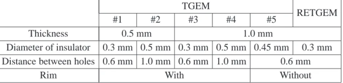
TGEM
#1 #2 #3 #4 #5 RETGEM
Thickness 0.5 mm 1.0 mm
Diameter of insulator 0.3 mm 0.5 mm 0.3 mm 0.5 mm 0.45 mm 0.3 mm Distance between holes 0.6 mm 1.0 mm 0.6 mm 1.0 mm 0.6 mm
Rim With Without
Table 1. The geometrical configurations of TGEM and RETGEM.
current is drawn due to a discharge. Thus, a continuous discharge could be efficiently suppressed. Furthermore, since the electrodes are made of an organic compound, the material budget is smaller than metal electrodes.
TGEM and RETGEM look very promising, but their basic properties have not yet been studied thoroughly. TGEM and RETGEM with different geometries were made, and the basic properties such as the voltage dependence of gain, gain variation as a function of time and energy resolution were measured.
2 Geometrical configurations of TGEM and RETGEM
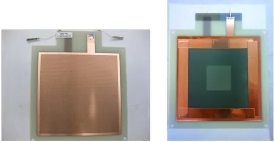
Figure1shows the plane views of TGEM and RETGEM. TGEM consists of a glass epoxy with 18 µm-thick copper electrodes. The electrodes of RETGEM are made of an organic compound and the resistance of the electrodes is about 100 kΩ/cm. Two configurations were tried for hole geometry; with and without rim. The cross sectional figure of TGEM with rim is shown at figure2. The purpose of having rim of 75µm around a hole, as shown in figure2, is to reduce a discharge frequency by suppressing the concentration of field flux to the hole edge.
The geometrical configurations of TGEM and RETGEM are summarized at table1. TGEMs with five different geometrical configurations were made; two different thickness, two different hole diameter and with and without rim. The geometrical characteristics of the TGEM without rim is the same with TGEM3 apart the diameter of the insulator. The geometrical characteristics of RETGEM is also the same with TGEM3 apart the rim. It is difficult to make rim at RETGEM due to the manufacturing aspect.
3 Setup
Figure3shows the schematic view of the test setup. In the measurement, 55Fe (X-ray: 5.9 keV) with an intensity of 80 kBq was used. The measurements were done with GEM in a single element. Distances between cathode mesh and GEM, and between GEM and anode pad are 20 mm and 1.5 mm, respectively. The voltage differences between cathode mesh and GEM, and between GEM and anode pad are 400 V. A signal was read using pad with active size of 10×10 mm2and was recorded using a VME ADC module. Ar(90%) + CH4(10%) gas mixture (P10) was used and
gas flow was kept 300 cc/min. Measurements have been done at atmospheric pressure and at room temperature (∼300 K).
2010 JINST 5 P03002
Figure 1. The plane view of TGEM (left) and RETGEM (right).
Figure 2. The cross sectional figure of TGEM
with rim. Figure 3. The schematic view of test setup
4 Result
In the case of the TGEMs other than TGEM3, a continuous discharge occurred before obtaining enough gain to separate the signal from the background. Two TGEMs were tested for each geo-metrical configuration and the similar results were obtained for both of the two TGEMs with the same geometrical characteristics. The following measurements were done using only TGEM3 and RETGEM.
4.1 Energy resolution
Figure4shows the charge distributions of TGEM3 and RETGEM at gain of∼2000. The highest peak corresponds to 5.9 keV and the escape peak (2.7 keV) was clearly seen in both cases. The energy resolution is defined as RMS of the Gaussian which is fitted to the highest peak. The energy resolution of TGEM3 is about 13%. It is significantly worse than that of the standard GEMs (∼10%) [7]. The energy resolution of RETGEM is about 10%, which is comparable to that of standard GEMs.
2010 JINST 5 P03002
Charge [fC]
0 20 40 60 80 100 120Count
0 20 40 60 80 100 120 140 160TGEM
Charge [fC]
0 20 40 60 80 100 120Count
0 20 40 60 80 100 120 140 160 RETGEMFigure 4. The charge distributions for TGEM and RETGEM.
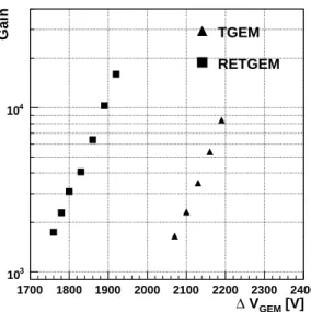
[V] GEM V ∆ 1700 1800 1900 2000 2100 2200 2300 2400 Gain 3 10 4 10 TGEM RETGEM
Figure 5. The voltage dependence of gain of TGEM and RETGEM.
4.2 Voltage dependence of gain
Figure5shows the voltage dependence of gain for TGEM3 and RETGEM. The gain (G) is calcu-lated as follows;
G= µ qe·ne
,
whereµ is the mean value of the 5.9 keV peak, qe is the elementary electric charge and ne is the
number of electrons created by the absorption of 5.9 keV X-ray. The voltage difference between GEM electrodes is called as∆VGEM in this report. The triangle and square symbols represent the
results of TGEM and RETGEM, respectively. The gain of TGEM3 achieved nearly 104, and that of RETGEM achieved over 104. A continuous discharge started at ∆VGEM = 2220 V (TGEM)
and at ∆VGEM = 1920 V (RETGEM). Thus, the measurements could not be conducted beyond
2010 JINST 5 P03002
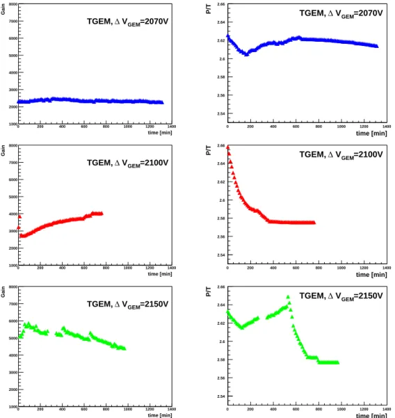
time [min] 0 200 400 600 800 1000 1200 1400 Gain 1000 2000 3000 4000 5000 6000 7000 8000 =2070V GEM V ∆ TGEM, time [min] 0 200 400 600 800 1000 1200 1400 P/T 2.54 2.56 2.58 2.6 2.62 2.64 2.66 =2070V GEM V ∆ TGEM, time [min] 0 200 400 600 800 1000 1200 1400 Gain 1000 2000 3000 4000 5000 6000 7000 8000 =2100V GEM V ∆ TGEM, time [min] 0 200 400 600 800 1000 1200 1400 P/T 2.54 2.56 2.58 2.6 2.62 2.64 2.66 =2100V GEM V ∆ TGEM, time [min] 0 200 400 600 800 1000 1200 1400 Gain 1000 2000 3000 4000 5000 6000 7000 8000 =2150V GEM V ∆ TGEM, time [min] 0 200 400 600 800 1000 1200 1400 P/T 2.54 2.56 2.58 2.6 2.62 2.64 2.66 =2150V GEM V ∆ TGEM,Figure 6. Left: Gain variation as a function of TGEM with∆VGEM=2070 V, 2100 V and 2150 V. Right:
Time variation of P/T during the measurement.
time [min] 0 200 400 600 800 1000 1200 1400 Corrected gain 0.8 0.9 1 1.1 1.2 1.3 1.4 1.5 1.6 1.7 1.8 =2100V, Gain:3000 GEM V ∆ =2070V, Gain:2000 GEM V ∆
Figure 7. The P/T dependence of the relative gain of TGEM.
2010 JINST 5 P03002
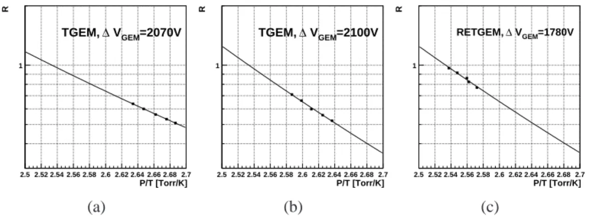
P/T [Torr/K] 2.5 2.52 2.54 2.56 2.58 2.6 2.62 2.64 2.66 2.68 2.7 R 1 =2070V GEM V ∆ TGEM, P/T [Torr/K] 2.5 2.52 2.54 2.56 2.58 2.6 2.62 2.64 2.66 2.68 2.7 R 1 =2100V GEM V ∆ TGEM, P/T [Torr/K] 2.5 2.52 2.54 2.56 2.58 2.6 2.62 2.64 2.66 2.68 2.7 R 1 =1780V GEM V ∆ RETGEM, (a) (b) (c)Figure 8. Gain dependence of P/T. (a): TGEM with∆VGEM= 20700 V. (b): TGEM with∆VGEM= 2100 V.
(c): RETGEM with∆VGEM= 1780 V.
4.3 Gain variation as a function of time
The left plots in figure6show the gain variation as a function of time for TGEM3. The top-left, middle-left and bottom-left figures show the result with∆VGEM = 2070 V, 2100 V and 2150 V,
respectively.
The gain of GEM changes as the pressure(P) and the temperature(T) changes. The gain varia-tion due to the variavaria-tion of P/T can be corrected at narrow P/T region [7]. The following function is used to correct the gain of TGEM with∆VGEM= 2070 V;
R=exp 29.87· 1 P/T −11.79 .
For the gain of TGEM with∆VGEM= 2100 V,
R=exp 41.88· 1 P/T −16.53 .
These functions are determined by fitting the data taken with the different pressure near the at-mospheric pressure and with almost the same temperature (∼300 K) (figure8). Figure7shows the result of the corrected gain of TGEM. The blue and the red triangles represent the results with
∆VGEM = 2070 V and with ∆VGEM = 2100 V, respectively. The gain variation of TGEM with ∆VGEM= 2150 V can not be explained by only the variation of P/T. The corrected gain of TGEM
with∆VGEM= 2070 V was within 6% and larger gain variation was seen at higher gain.
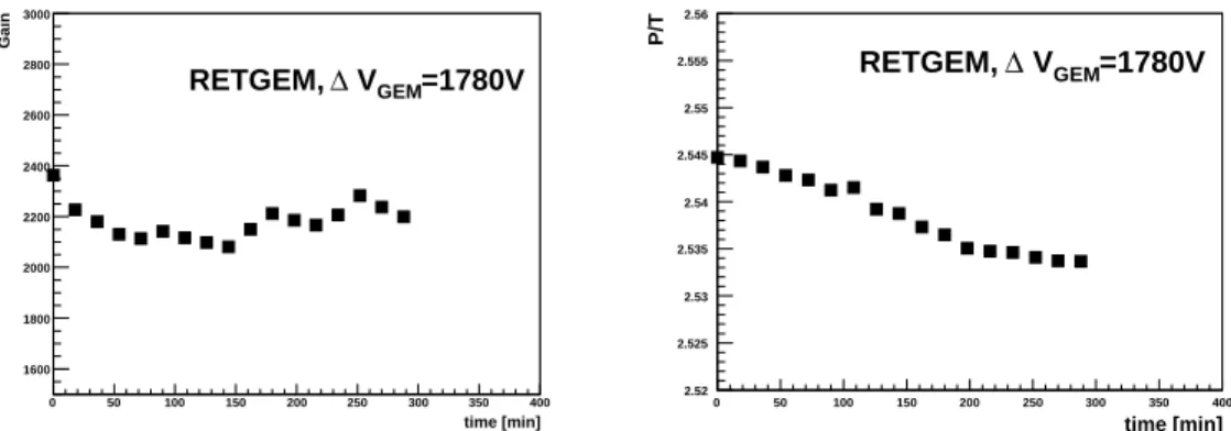
The gain of RETGEM was also corrected by P/T and the following function was used for the correction; R=exp 43.16· 1 P/T −17.04 .
After 100 minutes, the corrected gain was almost stable and the variation of the corrected gain is within 4% (figure10).
2010 JINST 5 P03002
time [min] 0 50 100 150 200 250 300 350 400 Gain 1600 1800 2000 2200 2400 2600 2800 3000 =1780V GEM V ∆ RETGEM, time [min] 0 50 100 150 200 250 300 350 400 P/T 2.52 2.525 2.53 2.535 2.54 2.545 2.55 2.555 2.56 =1780V GEM V ∆ RETGEM,Figure 9. Left: Gain variation as a function of time of RETGEM with∆VGEM=1780 V. Right: The P/T
value during the measurement.
time [min] 0 50 100 150 200 250 300 350 400 Corrected gain 0.8 0.85 0.9 0.95 1 1.05 1.1 1.15 1.2 =1780V GEM V ∆ RETGEM,
Figure 10. The corrected gain of RETGEM. The data are normalized by the mean value of datum.
5 Summary and outlook
TGEM with different geometrical configurations and RETGEM which has high resistive electrodes were made, and their basic properties such as voltage dependence of gain, energy resolution and gain variation as a function of time were measured.
For all TGEMs apart TGEM3, measurements could not be conducted due to a discharge. At this measurement, the energy resolution can be achieved≃13% (TGEM) and≃10% (RETGEM), which is comparable to that of micro-scale GEM (∼10%). The gain was obtained near 104 with
TGEM and over 104 with RETGEM without a continuous discharge. The gain variation as a function of time of TGEM with∆VGEM = 2070 V was within 6% after the correction by P/T and
larger gain variation was seen at higher gain. The gain variation as a function of time of RETGEM was within 4% after the correction by P/T. Since the gain variation as a function of time is a critical for stable operation, it is interesting to study the gain variation as a function of time of RETGEM with higher gain and for longer time.
References
[1] F. Sauli, GEM: a new concept for electron amplification in gas detectors,
Nucl. Instrum. Meth. A 386 (1997) 531.
2010 JINST 5 P03002
[2] M. Titov, New Developments and Future Perspectives of Gaseous Detectors,
Nucl. Instrum. Meth. A 581 (2007) 25[arXiv:0706.3516].
[3] Z. Fraenkel et al., A hadron blind detector for the PHENIX experiment at RHIC,
Nucl. Instrum. Meth. A 546 (2005) 466.
[4] S. Bachmann et al., High rate X-ray imaging using multi-GEM detectors with a novel readout design,
Nucl. Instrum. Meth. A 478 (2002) 104.
[5] L. Periale et al., Detection of the primary scintillation light from dense Ar, Kr and Xe with novel
photosensitive gaseous detectors,Nucl. Instrum. Meth. A 478 (2002) 377[physics/0106048]. [6] R. Oliveira, V. Peskov, F. Pietropaolo and P. Picchi, First tests of thick GEMs with electrodes made of a
resistive kapton,Nucl. Instrum. Meth. A 576 (2007) 362[physics/0701154].
[7] Y.L. Yamaguchi, Reaserch and Development of Gas Electron Multiplier (GEM) with a dry etching