Iranian Journal of Electrical & Electronic Engineering, Vol. 13, No. 4, December 2017 385
An Online Q-learning Based Agent LFC for a
Multi-Area Multi-Source Power System Including Distributed
Energy Resources
H. Shayeghi*
,**
(C.A.)and A. Younesi*
Abstract: This paper presents an online two-stage Q-learning based multi-agent (MA) controller for load frequency control (LFC) in an interconnected multi-area multi-source power system integrated with distributed energy resources (DERs). The proposed control strategy consists of two stages. The first stage is employed a PID controller which its parameters are designed using sine cosine optimization (SCO) algorithm and are fixed. The second one is a reinforcement learning (RL) based supplementary controller that has a flexible structure and improves the output of the first stage adaptively based on the system dynamical behavior. Due to the use of RL paradigm integrated with PID controller in this strategy, it is called RL-PID controller. The primary motivation for the integration of RL technique with PID controller is to make the existing local controllers in the industry compatible to reduce the control efforts and system costs. This novel control strategy combines the advantages of the PID controller with adaptive behavior of MA to achieve the desired level of robust performance under different kind of uncertainties caused by stochastically power generation of DERs, plant operational condition changes, and physical nonlinearities of the system. The suggested decentralized controller is composed of the autonomous intelligent agents, who learn the optimal control policy from interaction with the system. These agents update their knowledge about the system dynamics continuously to achieve a good frequency oscillation damping under various severe disturbances without any knowledge of them. It leads to an adaptive control structure to solve LFC problem in the multi-source power system with stochastic DERs. The results of RL-PID controller in comparison to the traditional PID and fuzzy-PID controllers is verified in a multi-area power system integrated with DERs through some performance indices.
Keywords:Multi-Agent, Reinforcement Learning, DERs, LFC, RL-PID.
1 Introduction1
HE size of the modern power systems is increased due to the interconnection of various energy resources to meet the increasing load demand. Load frequency control (LFC) of such power systems is more complex [1]. In addition, the amount of renewable
Iranian Journal of Electrical & Electronic Engineering, 2017. Paper first received 24 May 2016 and accepted 05 November 2017. * The authors are with the Department of Electrical Engineering, University of Mohaghegh Ardabili, Ardabil, Iran.
E-mails: [email protected] and [email protected].
** The author is with the Centre of Excellence for Power System Automation and Operation, Department of Electrical Engineering, Iran University of Science and Technology, Tehran, Iran.
Corresponding Author: H. Shayeghi.
energy production continuously on the rise due to serious issues like global warming, weak transmission lines, and outdated infrastructure of the power systems. On the other hand, inherent uncertainties in the output of the renewable energy resource such as photovoltaic (PV) and wind turbine generator (WTG) makes that the efficient frequency controller designing be more difficult. Moreover, an adaptive control strategy is required for interconnected operation modes [1-3]. Note that, the modern power system is subjected to frequency and tie-line power flow oscillations due to hourly energy production of DERs and load changings [4]. Thus, if a suitable controller is not considered for providing a good damping, the oscillations may persist for long time, causing disintegration of the system [5].
T
386 Iranian Journal of Electrical & Electronic Engineering, Vol. 13, No. 4, December 2017
Many researchers have employed various kind of LFC strategies to maintain the frequency and tie-line power flow of the electric network in their corresponding values [6-15]. Among the considered LFC methods, traditional controllers are the most widely used because of their simplicity, easy realization, low cost, and suitable reliability [6, 8, 11, 16]. In addition, different optimization algorithms like genetic algorithm, particle swarm optimization, differential search algorithm, and teaching-learning based optimization algorithm [7] are used for optimizing the dynamic performance of the traditional controllers. Since the fixed gains of a traditional controller are designed under a loading condition, it can’t guarantee the performance of the power system in the other operating conditions. This weakness should be resolved in LFC of multi-area multi-source power systems especially when they are integrated with the renewable energy resources (RERs) due to inherent uncertainties in the output of this type of energy sources. In the past several decades, fuzzy logic based controllers (FLCs) have been extensively used to cope with the power system uncertainties caused by changes in the system parameters and interconnection of stochastic DERs [11, 13, 14]. However, several serious problems regarding FLCs are reported in Refs. [11, 17]: i) Robustness is often assumed as a fundamental property of FLCs, thus, it is not taken into account during the tuning procedure. In fact, that is false. ii) Different parts of the FLCs such as membership functions (the numbers, limits, and the function types), fuzzy rules, and control gains should be optimized coordinately to achieve the optimal performance of the FLCs, which is time-consuming and a tedious work with an enormous computational burden.
In the recent years, different applications of the Q-learning solution of RL is reported in the power systems [18-22]. As reported in Ref. [18], RL based methods can cope with system nonlinearities and stochastic behaviors based on the partial information. They don’t need to any
knowledge about the system dynamics. These
characteristics are very useful for solving the LFC problem in a multi-area multi-source power system with RERs, to cope with serious problems such as dimensionality and different kinds of the uncertainties caused by system parameter changings, physical nonlinearities, and fickle output of the RERs. Since RL-based control methods learn the closed-loop control laws and update them continuously, they are known to be robust. Adaptive behavior is an important property for these controllers when the power system is faced with a situation, which is not experienced in its synthesis procedure. Because, RL paradigm updates its knowledge about the system dynamics continuously. Thus it can provide an adaptive damping control signal. Furthermore, MA-based controllers can be used in combination with traditional control methods to improve performances. Ahmed et. al [23] suggested two distinct RL based AGC algorithms. The first algorithm
works based on the area control error (ACE) signal, and the second one is based on the restoring the load generation balance. This study has two fundamental flaws, having large overshoot and slow system response. These shortcomings are due to improper selection of the MA action sets. The inherent complexities of the LFC emphasize on effective control strategy selection to damp the frequency and tie-line power flow oscillations perfectly.
According to the applicability of RL paradigm as a supplementary controller, here, RL technique is employed to supervise a classic PID controller, which is widely used in industry, to design an adaptive controller for solving LFC problem. The proposed control strategy is composed of two stages. The first stage is employed a PID controller which its gains are optimized with the sine-cosine (SCO) algorithm. The second stage is a supplementary control signal that is provided using RL technique. The well-known Q-learning approach is used for solving RL in this study. It should be mentioned that the proposed control strategy has two offline and online modes. The intelligent agents use the offline mode for learning the optimal control policy of LFC task. In the online mode, agents optimally control the plant by making the learned control laws and update their knowledge, too. The proposed LFC scheme successfully is applied to a three-area multi-source power system including DERs and physical nonlinearities such as time delay (TD), generation rate constraint (GRC), and governor dead band (GDB). Time domain performance of the RL-PID controller compared to PID and fuzzy-PID controllers.
The primary investigations of the present work are: i) To suggest an adaptive structure based on the RL
technique for supervising the existing PID controller for LFC task.
ii) To verify the robustness of the RL-PID controller under wide changes in loading pattern of RERs and severe system parameter changes.
iii)To study the dynamic performance of the proposed RL-PID controller in a multi-area multi-source power system including DERs and GRC, GDB and time delay.
iv)To compare the performance of the suggested RL-PID controller with the traditional optimized RL-PID and fuzzy-PID controllers by SCO algorithm the above power system.
2 Power System Modelling for AGC Problem
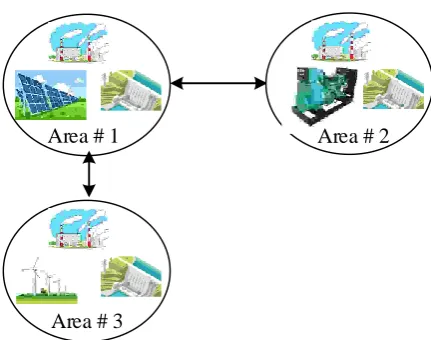
A three-area power system integrated with PV, WTG, and DEG units is utilized to verify the dynamic performance of the proposed RL-PID controller for solving LFC problem. All areas have a thermal unit and a hydropower station. Area 1, Area 2, and Area 3 have PV, DEG, and WTG, respectively. The simplified representation of the modern power system in a general form is shown in Fig. 1.
Iranian Journal of Electrical & Electronic Engineering, Vol. 13, No. 4, December 2017 387
Area # 1
Area # 3
Area # 2
Fig. 1 General scheme of the proposed three-area multi-source power system.
Governor with GDB
Turbine with GRC
-+
+
ΔPdiAREA# i
1
tT
1
s
+
-1
1
r r rK T s
sT
1
P PK
T s
1
1
ghsT
Mechanical Hydraulic Governor1
1
rs rhsT
sT
1
0.5
1
W WT s
T s
d
dt
1
s
Hydraulic Turbine with GRC
-+
apfi-1
apfi-2
1/Rth
1/Rhyd
ACEi
-+
TD1
1
gsT
ΔfiPower system Time delay
Cont roll er
2
18
900
100
500
s
s
s
ΔPPV
+
PV
1
DEG DEGK
T
s
DEG
+
1 2
(1
)
(1
)(1
)
wind w w
K
sT
sT
s
ΔPwind
Wind
+
-+
apfi-3
-+
apfi-3
-+
apfi-3
Δfi
1/RPV
1/RDEG
1/Rwind
Fig. 2 Block diagram of the ith area including thermal, hydropower and DESs.
2.1. Transfer Function of The Thermal and Hydro Power Stations
Transfer function model of the area #i of the power system including a thermal power plant with a hydropower station is shown in Fig. 2 [24, 25]. As shown in this figure, TD, GDB, and GRC are considered as the system physical limitations.
2.2 The Transfer Function Model of DERs
The transfer functions of the PV and DEG are represented by Eqs. (1) and (2), respectively [26, 27].
(1) 2 18 900 ( ) 100 50 PV s G s s s (2) ( ) 1 DEG DEG DEG DEG K P G s sT f
388 Iranian Journal of Electrical & Electronic Engineering, Vol. 13, No. 4, December 2017
The pitch control hydraulic actuator transfer function of WTG is given by Eq. (3) [28, 29]:
(3) 1 1 2 1 2 (1 ) ( )
( ) ( 1)(1 )
Wind W
k W
K sT
H s
U s T s sT s
since Tk is smaller than Tw2, it can be ignored. Thus, Eq.
(3) can be rewritten as Eq. (4).
(4)
1 1
1 2
(1 )
( )
( ) ( 1)(1 )
Wind W W
K sT
H s
U s sT s
3. The Proposed Controller
A simple illustration of the proposed two-stage RL-PID controller is shown in Fig. 3. In this figure, u is the control signal (area control error (ACE) in LFC problem), and y is the output of the controller. A distinct advantage of the proposed controller is that we can apply the stage two for updating the dynamic performance of the existing PID controller in LFC task
to achieve the desirable dynamic response
characteristics.
3.1 First Stage: The Classical Controller
The application of the PID controller in the industry is noteworthy. They are extensively used in industry due to their simplicity, easy to implement and the adequate performance they produce for a broad range of the process [30]. Considering the advantages of the PID controller, it is a suitable choice for employing in the first stage of the proposed strategy. Eq. (5) shows the mathematical formulation of the conventional PID controller.
(5)
p i d
du
y K K K udt dt
where, Kp, Ki, and Kd are proportional, integral, and derivative gains, respectively. Also, u is the input signal to the controller. Here, the controller gains of the
u First stage Q-learning based Multi-Agent controller PID controller Second stage y ++
The proposed Two stage RL-PID controller
Sine cosine algorithm
Preprocessing
Fig. 3 Illustrative model of the proposed adaptive Q-learning based PID controller.
proposed PID controller are tuned using the SCO algorithm [31].
3.1.1. Sine Cosine Algorithm, an Overview
The foundation of the SCO algorithm is built on the trigonometric sine and cosine functions. In general, the optimization process can be divided into two phases, exploration, and exploitation. In the first phase, the algorithm randomly combines the random solutions to find the best area of available solutions. But, in the second phase, the changing in the obtained solutions is gradual with a lower degree of randomness in comparison to the first phase [31]. Eq. (6) is used for updating the position of the population individuals in both phases.
(6)
1 1 2 3 4
1 2 3 4
sin( ) | | 0.5
cos( ) | | 0.5
t t t
t i i i
i t t t
i i i
X r r r P X r X
X r r r P X r
where, X ti is the position of the dimension i in the iteration t, r1-r4 are random numbers, and Pti is the position of the target point in iteration t of dimension i. The orientation and amount of the movement are determined using parameters r1 and r2, respectively. The
parameter r3 is a weight coefficient which increases
(r3>1) or decreases (r3<1) the effect of the target point.
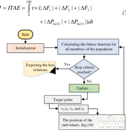
SC algorithm is explained in detail in [31]. Fig. 4 shows the flowchart of the SCO algorithm.
3.1.2 Optimization results
Since the power system under study is not symmetric, in each area one PID controller is considered. Each controller has three control gains. Thus, the proposed optimization problem has nine parameters should be tuned. The objective function, which is used for optimizing the PID controllers, is given by Eq. (7).
(7)
100
1 2 3
0
tie12 tie13
(| | | | | |
| | | |)
J ITAE t F F F
P P dt
Start Initialization
Calculating the fitness function for all members of the population
Target point Update ...
r1,r2, r3, and r4
The position of the individuals, Eq.(10) Stop criteria reached? Exporting the best
solutions
Yes
No
Fig. 4 flowchart of the SCO algorithm.
Iranian Journal of Electrical & Electronic Engineering, Vol. 13, No. 4, December 2017 389
Optimal tuning of the PID controllers is formulated as the following constraint optimization problem and solved using SCO algorithm.
(8)
min 1 2 3 max
min 1 2 3 max
min 1 2 3 max
Minimize subject to:
, ,
, ,
, ,
p p p p p
i i i i i
d d d d d
J
K K K K K
K K K K K
K K K K K
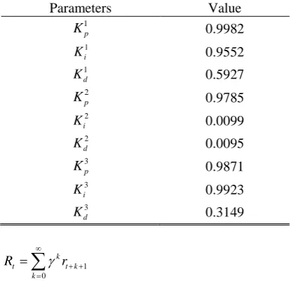
In this way, first population and the maximum number of iterations are considered as 30 and 50, respectively. Upper and lower limits of all parameters are considered equal to 0 and 1, respectively. The optimization results are shown in Table 1.
3.2 Second Stage: The Adaptive Reinforcement Learning Based Controller
Reinforcement learning is an algorithmic approach to solve stochastic optimal control problems by trial-and-error [18]. It describes how one (or more than one) agent interacts with its environment to learn an optimal control policy for satisfying a pre-defined goal. Optimal control policy means selecting the best action among all actions that exist for each state of the agent in the environment [32].
3.2.1 Q-Learning
Q-learning is one of the most known solution methods of the reinforcement learning which will be used in this paper. Simple structure, independent of the model of the system under control, robustness against changes in the operating point and system uncertainties and adaptive behavior are the most important advantages of the Q-learning based control methods [33, 34]. This control method can be utilized as a complementary controller for traditional controllers [32] to improve their performances. Q-learning based reinforcement learning assumes the environment (system under control) is divided into a finite number of states is shown with set {S}. Agent forms a matrix called Q, which has a value (initially ‘0’) for each set of action-state pairs and indicates the goodness of particular action in the corresponding state. In each time step, agent calculates its state st, and based on a defined strategy selects action a among available actions of stat st {A}. Immediately after applying the action, the agent takes a reward r
from the environment and calculates its next state st+1. Then it updates the corresponding element of the Q
matrix. The reward r shows the amount of satisfaction from the action a. This procedure will continue until satisfaction of pre-defined goal. The purpose of the Q-learning is to learn a strategy which maps the states to actions to maximize discounted long-term reward [33]. Discounted long-term reward of the system is given by Eq. (9).
Table 1 Optimal results of the PID controller parameters.
Parameters Value
1 p K 0.9982 1 i K 0.9552 1 d K 0.5927 2 p K 0.9785 2 i K 0.0099 2 d K 0.0095 3 p K 0.9871 3 i K 0.9923 3 d K 0.3149 (9) 1 0 k
t t k
k
R r
where, r is the reward, γ is a number at the range 0 to 1 and is called discount factor. This coefficient shows the importance of the future rewards in decision making. Setting γ = 0 means, the future rewards are ignored in decision making and setting γ = 1 means next rewards are considered in the decision-making process [34]. Q
matrix is defined as:
(10)
1 0
( , ) k | ,
t k t t k
Q s a E r s s a a
where, π, s, a, and r are the control policy, current state, selected action, and the received reward, respectively. In each time step, Eq. (10) should be updated using optimal Bellman equation, which is given by Eq. (11).
(11)
1 max ( 1, 1) ( , )
t t t t t
a
Q r Q s a Q s a
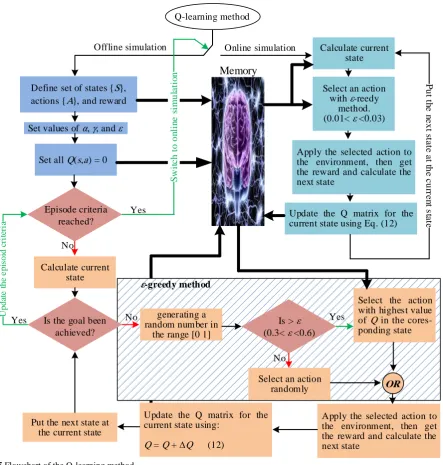
where, α is ϵ (0,1) and is called attenuation factor and shows the real amount of error [32]. The flowchart of the proposed Q-learning method is summarized in Fig. 5. It is evident from Fig. 5 that after completing the learning phase (offline simulation), the system will be switched to online simulation.
3.2.2 States, Actions, and Reward Definition
To achieve the desired level of satisfactory from Q-learning controller it is necessary to define the set of the states, actions, and reward function carefully. In the following, states, actions, and reward function definition for AGC problem are described in detail.
A. States
The primary aim of AGC is to balance the generation and demand to reduce the frequency fluctuations. In other word, this controller should damp the oscillations of the frequency and tie-line power flow. Thus, ∆f or
390 Iranian Journal of Electrical & Electronic Engineering, Vol. 13, No. 4, December 2017
Q-learning method
Offline simulation Online simulation
Memory
Define set of states {S}, actions {A}, and reward
Set values of α, γ, and ε
Set all Q(s,a) = 0
Episode criteria reached? Yes S w it c h t o o n li n e s im u la ti o n No Calculate current state
Is the goal been achieved? Yes U pda te t he e pi soi d cri te ri a
Is > ε (0.3< ε <0.6)
No generating a
random number in the range [0 1]
No
Select an action randomly
Select the action with highest value of Q in the cores-ponding state Yes
ε-greedy method
Apply the selected action to the environment, then get the reward and calculate the next state
OR
Update the Q matrix for the current state using:
Q = Q + Q (12) Put the next state at
the current state
Calculate current state
Select an action with ε-reedy
method. (0.01< ε <0.03)
Apply the selected action to the environment, then get the reward and calculate the next state
Update the Q matrix for the current state using Eq. (12)
P u t t h e n e x t s ta te a t t h e c u rr e n t s ta te
Fig. 5 Flowchart of the Q-learning method.
∆Ptie and or a combination of them can be used for state definition. Here, ∆f is intended for this purpose. In each time step for calculation of the current state of the agent of area i, ∆fi and its derivative are used. The range of -0.2 to -0.2 in ∆fi is discretized to 50 equal segments. Eq. (12) calculates the state of the agent of area i in each the time step t.
(12)
,
, ( ,, )
i t i t i t
d F S F dt B. Actions
Defining the set of actions is very complex and important. For simplicity based on a trial-and-error method and a set of three actions as Eq. (13) is considered for each state. Increasing the number of actions may improve the performance of the proposed controller but also, increases the time of learning
procedure.
(13)
{ 0.001, 0, 0.001}
A
C. Reward Function
Since, the purpose of this paper is to damp the frequency oscillations, the reward of the agent of area i
in time t is considered as the deviation of ∆f in area i
and all other areas. The reward function is calculated using Eq. (14).
(14)
,
1
1
1
Reward ( )
1 [ ]
1
( )
1 [ ]
i t t i k t j t j i j k t f k w f k
Iranian Journal of Electrical & Electronic Engineering, Vol. 13, No. 4, December 2017 391
where, wj is the weight coefficient of area j (j ≠ i) and is considered equal to 0.5 for areas that are directly connected to area i and equal to 0.3 for the other areas. Also, ε, α, and γ are considered as 0.02, 0.05, and 0.98, respectively.
4 Simulation Results
The suggested RL-PID controller is implemented in a three-area multi-source power system. The model of the
system under study has been developed in
MATLAB/SIMULINK® environment and the RL based
supplementary control signal for LFC task has been provided using a .m file. Power system parameters are given in Appendix A. The proposed control strategy utilized for LFC in the above power system compared to the SCO-tuned PID and fuzzy-PID controllers [35] in
different realistic power system scenarios. The control parameters of the used fuzzy-PID controller are optimized using SCO algorithm in the range [-2 2] and shown in Table 2. The details of the employed fuzzy-PID controller are described in [35].
4.1 Scenario 1
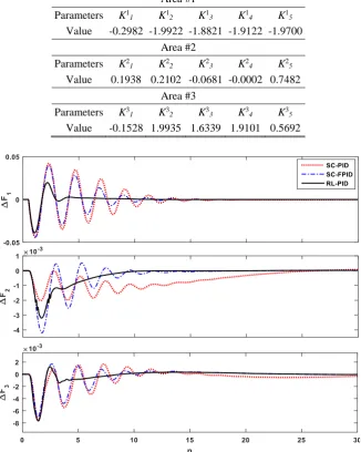
In this scenario, the dynamic performances of the LFC with 1% step load perturbation (SLP) and +25% change in the time constant of the governors in all areas, under the action of RL-PID, PID, and fuzzy-PID controllers are analyzed. The fluctuations in the frequency and tie-line power flow of the power system are represented in Figs. 6 and 7. The actions were taken by the agents of each area are shown in Fig. 8.
Table 2 Optimal results of the fuzzy PID controller parameters.
Area #1 Parameters K1
1 K12 K13 K14 K15
Value -0.2982 -1.9922 -1.8821 -1.9122 -1.9700 Area #2
Parameters K2
1 K22 K23 K24 K25
Value 0.1938 0.2102 -0.0681 -0.0002 0.7482 Area #3
Parameters K3
1 K32 K33 K34 K35
Value -0.1528 1.9935 1.6339 1.9101 0.5692
Fig. 6 Frequency deviations for 1% increasing in load demand in scenario 1.
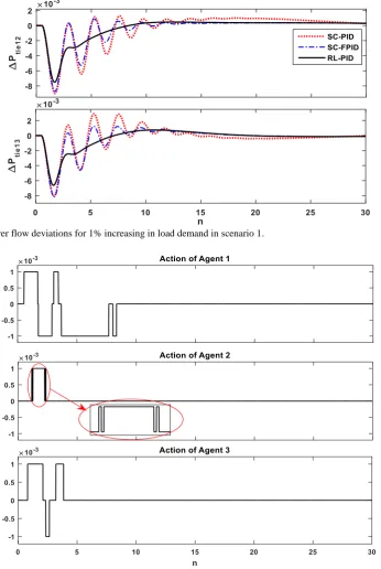
392 Iranian Journal of Electrical & Electronic Engineering, Vol. 13, No. 4, December 2017 Fig. 7 Tie-line power flow deviations for 1% increasing in load demand in scenario 1.
Fig. 8 The actions of the agent of each area in scenario 1.
It is evident from Figs. 6 and 7 that the proposed RL-PID controller effectively damped the oscillations faster than the traditional PID and fuzzy-PID controllers. According to Fig. 8, until the frequency deviations in each area are in the normal state (±0.02 × 0.2 in this paper), the RL controller is inactive and LFC task will perform entirely by the PID controller. However, when the deviations of the frequency in each area go out of the normal state due to any disturbance in any area, the RL controller provides the sufficient complement control signal and improves the frequency oscillation
damping. It is evident that when the deviations returned to the normal state the RL controller becomes inactive again.
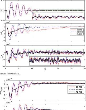
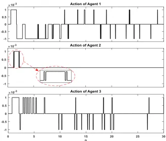
4.2 Scenario 2
To verify the superiority of the proposed adaptive LFC strategy, the dynamic response of the power system with 1% SLP in Area 1, the stochastic output of WTG in area 3 and PV in Area 1 in addition to -25% change in Tr and Kr in all areas are plotted in Figs. 9-11.
Iranian Journal of Electrical & Electronic Engineering, Vol. 13, No. 4, December 2017 393 Fig. 9 Frequency deviations in scenario 2.
Fig. 10 Tie-line power flow deviations in scenario 2.
According to the Figs. 9 and 10 it is clear that the superb damping performance of RL-PID in term of settling time and overshoot of frequency responses and tie-line power deviations are better than other controllers. The complement damping signals that are provided by the agent of each area are shown in Fig. 11.
4.3 Scenario 3
To show the robustness of the suggested RL-PID
controller against loading condition changing, in addition to 1% SLP in area 1, the loading condition is changed by +20% change in the DC gain of the power system (Kp) and -20% change in the time constant of the power system (Tp) at a same time. The dynamic performances of the LFC controllers are shown in Figs. 12-14 in this scenario.
394 Iranian Journal of Electrical & Electronic Engineering, Vol. 13, No. 4, December 2017 Fig. 11 Tie-line power flow deviations for 1% increasing in load demand in scenario 1.
Fig. 12 Frequency deviations in scenario 3.
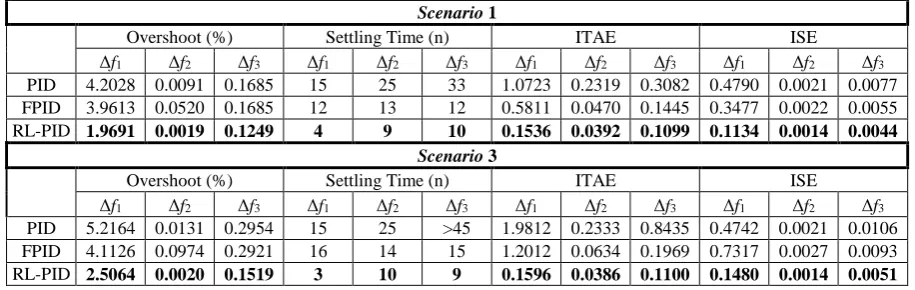
Figs. 12 and 13 show that the RL-PID controller is less sensitive to loading condition variations. Furthermore, to show the superiority of the proposed RL-PID controller over the fuzzy-PID and PID controllers optimized by SCO algorithm, time domain performance indices such overshoot(OS), settling time (Ts), ITAE, and ISE are calculated and shown in Table 3. ITAE and ISE are calculated using Eqs. (16) and (17).
(16)
90
1
[ ]
i i
n
ITAE f n
(17)
50 2 1
100 [ ]
i i
n
ISE f n
As the results is proved that the proposed controller is adaptive, simple and robust against parameter and loading condition changing.
Iranian Journal of Electrical & Electronic Engineering, Vol. 13, No. 4, December 2017 395 Fig. 13 Tie-line power flow deviations in scenario 3.
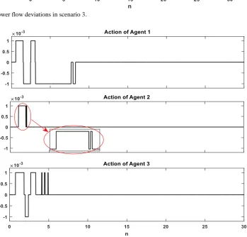
Fig. 14 The actions of the agent of each area in scenario 3.
From Table 3 the improvement in the relative time domain performance indices can be seen. According to the results, we can see that oscillations in area two of the power system are minuscule. This can be due to the presence of DEG in this area. The proposed control strategy has improved the performance of the traditional PID controller even better than fuzzy PID controller. Although the proposed controller is enhanced all characteristics of the deviations in frequency and
tie-line power flow, the largest impact is on the settling time. Since the RL-PID controller is based on discrete time simulation, it is reasonable to have a little impact on the overshoot/undershoot. Here, sampling time considered as 0.05 second. Reducing the sampling time improves the impact of the proposed controller on the overshoot/undershoot and its overall performance, but increases the simulation time and time to learning procedure, too.
396 Iranian Journal of Electrical & Electronic Engineering, Vol. 13, No. 4, December 2017 Table 3 Comparison of time domain performance indices for SC-PID, SC-FPID, and RL-PID controllers.
Scenario 1
Overshoot (%) Settling Time (n) ITAE ISE
Δf1 Δf2 Δf3 Δf1 Δf2 Δf3 Δf1 Δf2 Δf3 Δf1 Δf2 Δf3 PID 4.2028 0.0091 0.1685 15 25 33 1.0723 0.2319 0.3082 0.4790 0.0021 0.0077 FPID 3.9613 0.0520 0.1685 12 13 12 0.5811 0.0470 0.1445 0.3477 0.0022 0.0055 RL-PID 1.9691 0.0019 0.1249 4 9 10 0.1536 0.0392 0.1099 0.1134 0.0014 0.0044
Scenario 3
Overshoot (%) Settling Time (n) ITAE ISE
Δf1 Δf2 Δf3 Δf1 Δf2 Δf3 Δf1 Δf2 Δf3 Δf1 Δf2 Δf3 PID 5.2164 0.0131 0.2954 15 25 >45 1.9812 0.2333 0.8435 0.4742 0.0021 0.0106 FPID 4.1126 0.0974 0.2921 16 14 15 1.2012 0.0634 0.1969 0.7317 0.0027 0.0093 RL-PID 2.5064 0.0020 0.1519 3 10 9 0.1596 0.0386 0.1100 0.1480 0.0014 0.0051
5 Conclusions
In the present work, a two-stage adaptive MA-based controller has been presented for LFC study of a three-area multi-source power system including stochastic DERs and system physical nonlinearities. The suggested control strategy is composed of a traditional PID controller that is tuned using SCO algorithm and supervised by a supplementary control signal, which is provided using Q-learning method of RL paradigm. The proposed control scheme combines the features of the traditional PID controller like simplicity, suitable reliability, and easy realization with the important characteristics of multi-agent systems such as adaptive behavior, independent from the system model, and robustness against different kinds of uncertainties to develop an effective controller for solving the LFC problem in the modern power systems. Simulations are carried out in two phases, offline phase and online phase. The offline phase is based on the exploration and the intelligent agents learn the optimal policy of the LFC through interacting with the environment. The second phase is based on the exploitation and the autonomous agents optimally perform the LFC task based on the learned optimal control laws and update their knowledge. Eventually, the dynamic performance of the proposed RL-PID controller is verified compared to SCO tuned PID and fuzzy-PID controllers in the study of the LFC of a three-area modern power system considering system nonlinearities in some realistic scenarios. According to the results, it is evident that the dynamic performance of the suggested RL-PID controller is superb compared to both SCO tuned PID and fuzzy-PID controllers in terms of settling time, overshoot, ITAE, and ISE. Furthermore, it is found that the RL-PID controller is more robust and stable against different kinds of uncertainties due to the stochastic output of DERs and changes in the plant parameters and the system loading condition. In the other hand, the simple idea and structure of the proposed control strategy beside its amazing properties make it a suitable choice to implement in the real-time applications.
Appendix A. Power System Parameters
Data of The System
B1 = 0.425; B2 = B1; B3 = B1; Kps1 = 120; Kps2 = Kps1; Kps3
= Kps1; Tps1 = 20; Tps2 = Tps1; Tps3 = Tps1; RTH1 = 2.4; RTH2
= RTH1; RTH3 = RTH1; RHY1 = RTH1; RHY2 = RTH1; RHY3 =
RTH1; Tt1 = 0.3; Tt2 = Tt1; Tt3 = Tt1; Tt4 = Tt1; Tsg1 = 0.08;
Tsg2 = Tsg1; Tsg3 = Tsg1; Tsg4 = Tsg1; Kr1 = 0.5; Kr2 = Kr1;
Kr3 = Kr1; Kr4 = Kr1; Tr1 = 10; Tr2 = Tr1; Tr3 = Tr1; T12 =
0.0433; T13 = 0.0433; Tgh1 = 48.7; Tgh2 = Tgh1; Tgh3 =
Tgh1; Tw1 = 1; Tw2 = Tw1; Tw3 = Tw1; Trs1 = 0.513; Trs2 =
Trs1; Trs3 = Trs1; Trh1 = 10; Trh2 = Trh1; Trh3 = Trh1; a12 =-1;
a13 = -1;
Generation Rate Constraint (GRC) and Time Delay (TD)
GRCth = 0.02; TD = 0.05;GRChy_ub = 2.7; GRChy_lb = -3.6;
apf11 = 0.4; apf12 = 0.3; apf13 = 0.3;
apf21 = 0.4; apf22 = 0.4; apf23 = 0.2;
apf31 = 0.4; apf32 = 0.3; apf33 = 0.3; PV
Kpv = 1, Tpv = 1.8; Rpv = 2.4;
Disel Generator
Kdisel = 300-1; Tdiesel = 2; Rdisel = 2.4;
Wind Farm
RWind = 2.4; Twind1 = 6; Twind2 = 0.041; Kwind1 = 1.25;
Kwind2 = 1.4
References
[1] H. Shayeghi, A. Younesi, “A robust discrete fuzzyP+fuzzyI+fuzzyD load frequency controller for
multi-source power system in restructuring
environment,” Journal of Operation and Automation in Power Engineering, Vol. 5, No. 1, pp. 61-74, 2017.
Iranian Journal of Electrical & Electronic Engineering, Vol. 13, No. 4, December 2017 397
[2] P. K. Hota and B. Mohanty, “Automatic generation control of multi source power generation under deregulated environment,” International Journal of Electrical Power & Energy Systems, Vol. 75, pp. 205-214, 2016.
[3] F. Daneshfar and E. Hosseini, “Load-frequency control in a deregulated environment based on bisection search,” Iranian Journal of Electrical & Electronic Engineering, Vol. 8, pp. 303-310, 2012. [4] H. Rajabi Mashhadi, S. M. Eslami, and H. Modir
Shanechi, “Analysis of wind speed forecasting error
effects on automatic generation control
performance,” Iranian Journal of Electrical & Electronic Engineering, Vol. 10, pp. 223-229, 2014. [5] O. Abedinia, N. Amjadi, A. Ghasemi, H. Shayeghi,
“Multi-stage fuzzy load frequency control based on multi-objective harmony search algorithm in deregulated environment,” Journal of Operation and Automation in Power Engineering, Vol. 1, No. 1, pp. 63-73, 2013.
[6] A. Khodabakhshian and R. Hooshmand, “A new PID controller design for automatic generation control of hydro power systems,” International Journal of Electrical Power & Energy Systems, Vol. 32, pp. 375-382, 2010.
[7] D. Guha, P. K. Roy, and S. Banerjee, “Study of differential search algorithm based automatic generation control of an interconnected thermal-thermal system with governor dead band,” Applied Soft Computing, Vol. 52, pp. 160-175, 2017. [8] N. Pathak, T. S. Bhatti, and A. Verma, “New
performance indices for the optimization of controller gains of automatic generation control of
an interconnected thermal power system,”
Sustainable Energy, Grids and Networks, Vol. 9, pp. 27-37, 2017.
[9] Y. Xu, F. Li, Z. Jin, and C. Huang, “Flatness-based adaptive control (FBAC) for STATCOM,” Electric Power Systems Research, Vol. 122, pp. 76-85, 2015. [10]B. K. Sahu, S. Pati, P. K. Mohanty, and S. Panda, “Teaching–learning based optimization algorithm based fuzzy-PID controller for automatic generation control of multi-area power system,” Applied Soft Computing, Vol. 27, pp. 240-249, 2015.
[11]M. H. Khooban and T. Niknam, “A new intelligent online fuzzy tuning approach for multi-area load frequency control: Self Adaptive Modified Bat Algorithm,” International Journal of Electrical Power & Energy Systems, Vol. 71, pp. 254-261, 2015.
[12]D. K. Sahoo, R. K. Sahu, G. T. C. Sekhar, and S. Panda, “A novel modified differential evolution algorithm optimized fuzzy proportional integral derivative controller for load frequency control with thyristor controlled series compensator,” Journal of Electrical Systems and Information Technology, 2016.
[13]P. C. Pradhan, R. K. Sahu, and S. Panda, “Firefly algorithm optimized fuzzy PID controller for AGC of multi-area multi-source power systems with
UPFC and SMES,” Engineering Science and
Technology, an International Journal, Vol. 19, pp. 338-354, 2016.
[14]D. K. Chaturvedi, R. Umrao, and O. P. Malik, “Adaptive polar fuzzy logic based load frequency controller,” International Journal of Electrical Power & Energy Systems, Vol. 66, pp. 154-159, 2015.
[15]H. Yousef, “Adaptive fuzzy logic load frequency control of multi-area power system,” International Journal of Electrical Power & Energy Systems, Vol. 68, pp. 384-395, 2015.
[16]M. R. Sathya and M. Mohamed Thameem Ansari, “Design of biogeography optimization based dual mode gain scheduling of fractional order PI load
frequency controllers for multi source
interconnected power systems,” International
Journal of Electrical Power & Energy Systems, Vol. 83, pp. 364-381, 12// 2016.
[17]P. Alberto and A. Sala, “Fuzzy logic controllers. Advantages and drawbacks.,” in XIII Congreso de la Asociation Chilena de Controlo Automatico, 1998, pp. 833-844.
[18]D. Ernst, M. Glavic, and L. Wehenkel, “Power systems stability control: reinforcement learning framework,” IEEE Transactions on Power Systems, Vol. 19, pp. 427-435, 2004.
[19]T. Yu and W. G. Zhen, “A reinforcement learning approach to power system stabilizer,” in Proc. of the IEEE Power & Energy Society General Meeting, Calgary, AB, pp. 1-5, 2009.
[20]X. Zhang, T. Yu, B. Yang, and L. Cheng, “Accelerating bio-inspired optimizer with transfer
reinforcement learning for reactive power
optimization,” Knowledge-Based Systems, Vol. 116, pp. 26-38, 2017.
[21]J. G. Vlachogiannis and N. D. Hatziargyriou, “Reinforcement learning for reactive power control,” IEEE Transactions on Power Systems, Vol. 19, pp. 1317-1325, 2004.
[22]V. Nanduri and T. K. Das, “A Reinforcement Learning Model to Assess Market Power Under Auction-Based Energy Pricing,” IEEE Transactions on Power Systems, Vol. 22, pp. 85-95, 2007.
[23]T. P. Imthias Ahamed, P. S. Nagendra Rao, and P. S. Sastry, “A reinforcement learning approach to automatic generation control,” Electric Power Systems Research, Vol. 63, pp. 9-26, 2002.
[24]T. S. Gorripotu, R. K. Sahu, and S. Panda, “AGC of a multi-area power system under deregulated environment using redox flow batteries and interline power flow controller,” Engineering Science and Technology, an International Journal, Vol. 18, pp. 555-578, 2015.
398 Iranian Journal of Electrical & Electronic Engineering, Vol. 13, No. 4, December 2017
[25]S. R. Khuntia and S. Panda, “Simulation study for automatic generation control of a multi-area power
system by ANFIS approach,” Applied Soft
Computing, Vol. 12, pp. 333-341, 2012.
[26]D. J. Lee and L. Wang, “Small-signal stability analysis of an autonomous hybrid renewable energy power generation/energy storage system Part I: Time-domain simulations,” IEEE Transactions on Energy Conversion, Vol. 23, pp. 311-320, 2008. [27]S. A. Jeddi, S. H. Abbasi, and F. Shabaninia, “Load
frequency control of two area interconnected power system (Diesel Generator and Solar PV) with PI and FGSPI controller,” in The 16th CSI International Symposium on Artificial Intelligence and Signal Processing (AISP 2012), pp. 526-531, 2012.
[28]D. Das, S. K. Aditya, and D. P. Kothari, “Dynamics of diesel and wind turbine generators on an isolated power system,” International Journal of Electrical Power & Energy Systems, Vol. 21, pp. 183-189, 1999.
[29]R. K. Sahu, T. S. Gorripotu, and S. Panda, “Automatic generation control of multi-area power systems with diverse energy sources using teaching learning based optimization algorithm,” Engineering Science and Technology, an International Journal, Vol. 19, pp. 113-134, 2016.
[30]R. D. O. Pereira, M. Veronesi, A. Visioli, J. E. normey-Rico, and B. C. Torrico, “Implementation and test of a new autotuning method for PID controllers of TITO processes,” Control Engineering Practice, Vol. 58, pp. 171-185, 2017.
[31]S. Mirjalili, “SCA: a sine cosine algorithm for solving optimization problems,” Knowledge-Based Systems, Vol. 96, pp. 120-133, 2016.
[32]R. Hadidi and B. Jeyasurya, “Reinforcement learning based real-time wide-area stabilizing control agents to enhance power system stability,”
IEEE Transactions on Smart Grid, Vol. 4, pp. 489-497, 2013.
[33]C. J. C. H. Watkins and P. Dayan, “Technical note: Q-Learning,” Machine Learning, Vol. 8, pp. 279-292.
[34]N. Vlassis, A Concise Introduction to Multiagent Systems and Distributed Artificial Intelligence, Morgan and Claypool Publishers, 2007.
[35]H. Shayeghi, A. Younesi, and Y. Hashemi, “Optimal design of a robust discrete parallel FP + FI + FD controller for the automatic voltage regulator system,” International Journal of Electrical Power & Energy Systems, Vol. 67, pp. 66-75, 2015.
H. Shayeghi received the B.S. and M.S.E. degrees in Electrical and Control Engineering in 1996 and 1998, respectively. He re ceived his Ph.D. degree in Electrical Engineering from Iran University of Science and Technology, Tehran, Iran in 2006. Currently, he is a full Professor in Technical Engineering Department of University of Mohaghegh Ardabili, Ardabil, Iran. His research interests are in the application of robust control, artificial intelligence and heuristic optimization methods to power system control design, operation and planning and power system restructuring. He has authored and co-authored of 5 books in Electrical Engineering area all in Farsi, one book and two book chapters in international publishers and more than 330 papers in international journals and conference proceedings. Also, he collaborates with several international journals as reviewer boards and works as editorial committee of three international journals. He has served on several other committees and panels in governmental, industrial, and technical conferences. He was selected as distinguished researcher of the University of Mohaghegh Ardabili several times. In 2007 and 2010 he was also elected as distinguished researcher in engineering field in Ardabil province of Iran. Furthermore, he has been included in the Thomson Reuters’ list of the top one percent of most-cited technical Engineering scientists in 2015 and 2016, respectively. Also, he is a member of Iranian Association of Electrical and Electronic Engineers (IAEEE) and Senior member of IEEE.
A. Younesi received B.S and M.S.E degrees both in Electrical Engineering from Faculty of Technical Eng. Department of the Mohaghegh Ardabili University, Ardabil, Iran in 2012 and 2015 respectively. Currently He is a PhD. student in Technical Eng. Department of the University of Mohaghegh Ardabili, Ardabil, Iran. His areas of interest are application of artificial intelligence in power system automation and control, application of Reinforcement Learning to power system control, Fuzzy Systems, Heuristic optimization in power system control. He is a student member of Iranian Association of Electrical and Electronic Engineers (IAEEE) and IEEE.