DOA
E
stimation and
A
daptive
B
eamforming for
S
mart
A
ntenna
S
ystem using
DSP A
lgorithm
A TIGA RI A NGELA FELICE (B.Tech) 1
KA SSULA SOUNDA RYA (B. Tech) 2
KEMBA SRUJA NA (B. Tech) 3
V. SUDA RSHINI KA TA KSHA M (M.Tech, Assistant professor)4
Stanley College of Engineering and technology for women, Hyderabad, Telangana (500001), INDIA
an g elafelice27@g mail.co m1 s o u n d ary a7kas s u la@g mail.co m2 s ru jan akemb a95@g mail.co m3
v s u d ars h an i@s tan ley .ed u .in4
Abstract
In this paper a tool for the modeling analysis and simulation of direction-of-arrival (DOA) estimation and in the design of smart antenna arrays for wireless communication adaptive beam forming is needed. The use of studying adaptive beam forcing is to estimate the three different algorithms as MUSIC, MVDR and LMS. The directions of arrival and number of incident signals are estimated by the MUSIC and the arrival of desired signal is also given by MUSIC. The optimum weight vector will maximize the output signal to noise ratio and interference ratio (SNIR) of multiple antennas. So to obtain the optimum weight vector minimum variance distortion less response (MVDR) is used. LMS is very efficient and robust in application.
Key wo rd s : Adaptive Beam forming, Direction-of Arrival (DoA), MUSIC (Multiple Signal Classifier), RLS (Recursive Least Square), Smart antenna (SA), LMS.
1.
I
NTRODUCTION
At present, many researchers have been motivated to enhance the wireless network capacity by providing high quality wireless access. The Smart antenna (SA) technology is gaining more and more
interest in increasing the wireless network capacity [1] that helps to meet the demand for the subscriber growth and the high speed. Smart antenna is
recognized as most promising technology in 3G wireless network for higher user capacity by effectively reducing the multipath and cochannel interference and thereby enhancing the data rate.
The conventional base station antennas were Omnidirectional i.e. they used to radiate power in all direction, where there will be a waste of resources since power is radiated in all direction other than the desired user view of direction. Also the signal experiences the interference at the receiver side. To overcome this all problems, smart antennas were developed.
or reduce multipath fading and cochannel interference.
For optimal processing, the typical objective is maximizing the output signal-to-noise ratio (SNR). For an array with a specified response in the direction of the desired signal, this is achieved by minimizing the mean output power of the processor subject to specified constraints. In the absence of errors, the beam pattern of the optimized array has the desired response in the signal direction and reduced response in the directions of unwanted interference. The weights of the array system determine system performance. The selection process of these weights depends on the application and leads to various types of beamforming schemes.
Organization of this paper is as follows. Section 2 provides an overview of smart antenna. Section 3 presents a short description of adaptive beamforming algorithm. Section 4 presents the implementation DOA estimation methods MUSIC & MVDR algorithms. Section 5 presents the implementation of LMS algorithm. Whereas simulation results are given in Section 6.
2.
SMART
ANTENNA
A . Smart A n ten n as
Smart antennas can provide higher system capacities, increase signal to noise ratio, reduce multipath and co-channel interference by steering the main beam
towards the user and at the same time forming nulls in the directions of the interfering signal. However, several challenges remain in the development of these adaptive systems and it requires complicated adaptive algorithms to steer the beam and the nulls.
B. Ty p es o f s mart an ten n a
There are two types of smart antennas and they are switched beam smart antennas and adaptive array smart antennas. Switched beam systems have several available fixed beam patterns. A decision is made as to which beam to access, at any given point in time, based upon the requirements of the system. Adaptive arrays allow the antenna to steer the beam to any direction of interest while simultaneously nulling interfering signals.
i. Switch ed Beam A n ten n as
It form multiple fixed beams with heightened sensitivity in particular directions. These antenna systems detect signal strength, choose from one of several predetermined, fixed beams, and switch from one beam to another as the mobile moves throughout the sector.
ii. A d ap tiv e A rray A n ten n as
Adaptive antenna technology represents the most advanced smart antenna approach by using a variety of new signal-processing algorithms. It provides optimal gain while simultaneously identifying, tracking, and minimizing interfering signals.
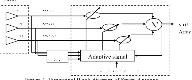
Figure 1. Functional Block diagram of Smart Antenna
1
2
N
D
OA Adaptive signal
∑
Available information X1(t)
X2(t)
XN (t)
y (t) Array output Array
C. Th eoretical mo d el fo r s mart an ten n a Sy s tem A smart antenna combines antenna arrays with digital signal processing units in order to improve reception and transmission of radiation patterns dynamically in response to the signal environment. It can increase channel capacity, extend range coverage, steer multiple beams to track many mobiles, compensate aperture distortion or reduce multipath fading and cochannel interference.
The smart antenna system needs to differentiate the desired signal from the cochannel interferences and
normally requires either the knowledge of a reference signal (or training signal), or the direction of the desired signal source. There exists a range of schemes to estimate the direction of sources with conflicting demands of accuracy and processing power. Similarly, there are many methods and algorithms to update the array weights, each with its speed of convergence and required processing time. "Fig. 1,” shows the functional block diagram of smart antenna system.
The smart antenna system can be divided mainly into three parts.
1) The first one performs the direction of arrival (DOA) estimation and determines the number of incoming signals.
2) The second part performs the DOA classification. It finds out which signals originate from the user and which ones from the interferers.
3) The third part consists in the beamforming algorithm. It forms an antenna pattern with a main beam steered in the direction of the user, while minimizing the influence of the interfering signals and the noise. An antenna array has spatially separated sensors whose outputs are fed into a weighting network. In general any combination of elements in different geometric structures can form an array.
3.
LITERATURE R
EVIEW
Assimakis K. Leros and Vassilios C. Moussas presents an adaptive approach to the problem of estimating the direction of arrival angles of narrowband signals emitted from multiple sources. We reformulatemulti-model partitioning algorithm combined with extended Kalman filters for combined identification of the number of sources and
estimation of the angles of arrival. The proposed algorithm’s performance is assessed by simulation in several operational scenarios. The results presented demonstrate that the algorithm is capable of tracking changes in the angles of arrival and of detecting variations in the number of sources present Suchita W. Varade K. D. Kulat-Robust Algorithms for DOA Estimation and Adaptive Beamforming for Smart Antenna Application Second International Conference on Emerging Trends in Engineering and Technology ICETET-2009 [7]
In this performance of adaptive beamforming algorithm has been studied for two different DOA estimation algorithms namely MUSIC & MVDR estimates the number of incident signals on the array and their directions of arrival. It also gives the direction of arrival desired signal the Minimum Variance Distortion less Response (MVDR) is a very well known algorithm to obtain the optimum weight vector which maximizes the output s ignal to noise and interference ratio (SNIR) of multiple antennas.
algorithms Simulation result shows that beamforming reduces the interference power significantly thereby increasing output signal to interference-noise ratio (SINR). This paper includes simulation results and performance analysis of these beamforming techniques depending on the application one of the methods is selected for deployment of beamforming antenna.
4.
ADAPTIVE
BEAMFORMING
The adaptive algorithm used in the signal processing has a profound effect on the performance of a Smart Antenna system. Although the smart antenna system is sometimes called the ―Space Division Multiple Access it is not the antenna that is smart. The function of an antenna is to convert electrical signals into electromagnetic waves or vice versa but nothing else. The adaptive algorithm is the one that gives a smart antenna system its intelligence without an adaptive algorithm the original signals can no longer be extracted. In the fixed weight beam forming approach the arrival angles does not change with time so the optimum weight would not need to be adjusted. However if desired arrival angles change with time it is necessary to devise an optimization scheme that operates on-the-fly so as to keep recalculating the optimum array weight that’s done by using adaptive beam forming algorithm.
5.
DIRECTION OF
ARRIVAL (DOA)
ESTIMATION
A . DOA ESTIM A TION
Several algorithms have been developed for DOA estimation [7]-[9], [16] and [19]-[21]. The purpose of this estimation is that to acquire the information from the array element and determine the angle of direction of the desired user or signal and gives that output to the digital signal processor (adaptive beamforming algorithms). The different types of DoA estimation algorithms are
MUSIC (Multiple Signal Classifier)
ESPRIT (Estimation of Signal Parameters via Rotational Invariance Techniques). MUSIC is high resolution technique based on exploiting the Eigen structure of input covariance matrix. In this paper, MUSIC algorithm is implemented for DOA estimation. This algorithm uses the Eigen values and Eigen vectors of the covariance matrix of the antenna array to determine the direction of sources based on the properties of the signal and noise subspace.
If there are D signals incident on the array, the received input data vector at an M-element array can be expressed as a linear combination of the D incident waveforms and noise
𝑢 = ∑ 𝑎(𝜙1) 𝐷
𝑙 =1
𝑆1+ 𝑛 = 𝐴𝑆 + 𝑛 (1)
Where A is the matrix of steering vectors,
𝐴 = [𝑎(𝜙1)𝑎(𝜙1) … . . 𝑎(𝜙𝐷)]
The received vectors and the steering vectors can be visualized as vectors in an M-dimensional vector space. The input covariance matrix is
𝑅𝑢𝑢 = 𝐸[𝑢𝑢𝐻] = 𝐴𝑅𝑆𝑆𝐴𝐻+ 𝜎𝑛2 (2)
The DOA’s of the multiple incident signals can be estimated by locating the peaks of a MUSIC spatial spectrum.
𝑃(𝜙) = 𝐸 1
𝑎𝐻(𝜙)𝑉
𝑛𝑉𝑛𝐻𝑎(𝜙)
(3)
B. IM PLEM ENTATION OF M VDR ALGORITHM
Figure2 shows a uniform linear array (ULA) of N equispaced sensors. A number of plane waves from M narrowband sources impinging from different angles𝜃𝑖, i = 1, 2, …, M. At a particular instant of
The signal vector x (t) can be defined as different angles 𝜃𝑖, i = 1, 2, …, M.
𝑥(𝑡) = ∑ 𝑎(𝜃𝑚)𝑠𝑚(𝑡) 𝑀
𝑚=1
(4)
𝑎(𝜃) is referred as array response so that,array steering vector is defines as
𝑎(𝜃) = [1 𝑒−𝑗𝜙… … . . 𝑒−𝑗(𝑁−1)𝜙]𝑇 (5)
Figure2 .Uniform Linear Array with M- Element
Where T is the transposition operator and 𝜙
represents the electrical phase shift from element to element along the array, 𝜙 can be defined by:
𝜙 = (2𝜋 𝜆⁄ )𝑑 cos 𝜃
The signal vector 𝑥(𝑡) of size N×1 can be written as
𝑥(𝑡) = 𝐴. 𝑠(𝑡)
The array output consists of the signal plus noise components, and it can be defined as:
𝑢(𝑡) = 𝑥(𝑡) + 𝑛(𝑡)
Where x(t) and n(t) are signal and noise components. Equation 1 can be written in matrix form of size N×K as:
𝑈 = 𝐴. 𝑆 + 𝑁
The spatial correlation matrix R of the observed signal vector u (t) can be defined as:
𝑅 = 𝐸[𝑢(𝑡) . 𝑢(𝑡)𝐻] (6)
The spatial correlation matrix R can now be expressed as:
𝜃 dsin𝜃
Wave front
𝑤1 𝑤2 𝑤3 𝑤𝑁
∑
Pattern forming network Far field signal
source (wavelength=𝜆)
𝜃
Array Boresight
Array output
1 3
𝐸⌊𝐴. 𝑠(𝑡) . 𝑠(𝑡)𝐻. 𝐴𝐻⌋ + 𝐸⌊𝑛(𝑡). 𝑛(𝑡)𝐻⌋ (7)
gain is defined as
min 𝐸[|𝑦(𝜃)|2] = min 𝑤𝐻𝑅𝑤 , 𝑤𝐻𝐴 = 1 (8)
The output power of the array as a function of the DOA estimation, using MVDR beamforming method, is given by MVDR spatial spectrum as,
𝑊 = 𝑅−1𝐴
𝐴𝐻𝑅−1𝐴 (9)
𝑃𝑀𝑉𝐷𝑅(𝜃) = 1
𝐴𝐻𝑅−1𝐴 (10)
6.
IMPLEMENTATION OF LMS
ALGORITHM
This algorithm was first developed by Widrow and Hoff in 1960. The design of this algorithm was
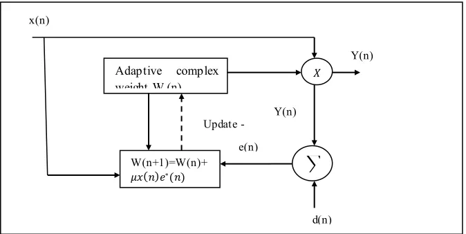
stimulated by the Wiener-Hopf equation. By modifying the set of Wiener Hopf equations with the stochastic gradient approach a simple adaptive algorithm that can be updated recursively we developed. This algorithm was later on known as the least-mean-square (LMS) algorithm. The algorithm contains three steps in each recursion: the computation of the Processed signal with the current set of weights the generation of the error between the processed signal and the desired signal and the adjustment of the weights with the new error information by the gradient method. This algorithm like the preceding one requires a reference signal and it computes the weight vector using the equation.
𝑤 (𝑛 + 1) = 𝑤 (𝑛) + 𝜇𝑥(𝑛)[𝑑 ∗ (𝑛) − 𝑥𝐻(𝑛) 𝑤(𝑛)]
Figure 3. LMS bam former
W(n+1)=W(n)+ 𝜇𝑥(𝑛)𝑒∗(𝑛)
Adaptive complex weight W (n)
∑ 𝑋
d(n) Y(n)
e(n) x(n)
Y(n)
7. S
IMULATION RESULTS
Figure 4. MUSIC Algorithm Result
Figure 5. LMS Algorithm Result
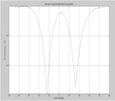
Figure 6. MVDR Algorithm Result
Figure 7. GUI Result
8. C
ONCLUSION
F
UTURE S
COPE
The project can be extended with various integration to this modelled system, as it is depending on DOA estimation and beam-forming of a signal which can be calculated and estimation more precisely by intergrating this system to GPS system so that the receiver is achieved with gain and good directionality.
R
EFERENCES
[1] Raed M. Shubair, Mahmoud A. Al-Qutayri, and Jassim M. Samhan” A Setup for the Evaluation of MUSIC and LMS Algorithms for a Smart Antenna System Journa of Communications, Vol.2 No.4 ,June2007
[2] R. M. Shubair and A. Merri, "Convergence of adaptive beamforming algorithms forwireless communications," Proc. IEEE and IFIP International Conference on Wireless and Optical Communications Networks, Dubai, UAE, March 6-8, 2005
[3] R. M. Shubair and A. Merri, "Robust algorithms for direction finding and adaptive beamfomning: performance and optimization," Proc. IEEE International Midwest Symposium on Circuits and Systems, Hiroshima, Japan, July 25-28, 2004, pp. 589-592.4
[4] Angeliki Alexiou and Martin Haardt, “Smart antenna technologies for future wireless systems: Trends and Challenges”, IEEE Comm. Magazine, pp. 90-97, September 2004. [5] R. M. Shubair “robust adaptive beamfoming using LMS algorithm with SMI initialization” 0-7803-8883- 6/05/$20.00 x2005 . IEEE