A Review on Modern Pulse Width Modulation
Techniques Based Inverters
Manish Sahajwani1, Sushma Patel 2
HOD, Dept. of EX, IES IPS Academy Indore (M.P.) India1
M.E. Scholar (Power Electronics), Dept. of EX
,
IES IPS Academy Indore (M.P.) India2ABSTRACT: The modern inverter technology for serving the society through comfort, making not only changes the domestic life style but in industries where VFD and other lifting & tackles require a new and efficient technology for betterment of performance of the drive and lifting tackles. Here the paper gives the schematic work of various scholars and comparison of different techniques of different pulse width modulation techniques for Power Electronics Inverters used for different industrial and commercial applications.
This paper presents few approaches of above, their brief introduction and literature review.
KEYWORDS: PWM, SPWM, SVPWM, Firing Pulse,Inverter
I.INTRODUCTION
Earlier the utilization of electrical energy was simple and straight forward; generation of electricity & its consumption was a linear process, but now a day’s electrical power system is one of the complex networks in the world with the invention of new techniques of power control and equipment which have better energy efficiency and efficient control with fast and smart switching [1, 2]. Since the development of semiconductor devices in the decades of the 1950s the use of ithas been increased not only in the field of electronics or communication engineering but electrical engineering too. In Earlier days the switching of electric power for the operation of electrical equipments was either through manual or through electromechanical switches, but due to fast speed, accuracy and high range the power electronics and solid state controllers and converters have been used worldwide and in the last two decades their use increases very rapidly[3].
The inversion process of converting DC into AC has taken place for many applications such as renewable energy technology, HVDC transmission, Adjustable speeddrives[4] and high frequency industrial heating processes. The applications using variable frequency inverters are increasing day by day due to its user friendly approach for common men while the technology behind this is very advanced.
The aim of this paper is to review, classify and illustrate the pulse width modulation techniques. Here is a comparison among Cycloconverter, LCI and PWM supply is given in the table shows that how the technology has advantages over other two[2, 5] for different uses in electrical engineering systems pulse width modulation techniques have proven superiority over other techniques
Table 1
Comparison between different technologies for inverters
Sr. No. Control Feature Cyclo-converter LCI PWM 1 Speed (in Drive) Limited Wide Wide 2 Dynamic response Excellent Good Excellent 3 Torque pulsation Low High Very Low 4 Stability,Good Good Moderate Very good 5 Volumetricpower
density
II. PULSE WIDTH MODULATION TECHNIQUES AND COMPARISON
Different approaches and classification of PWM techniques has been shown in fig. 1 [4,7]:
Figure 1 Classification of PWM Technique
The figure shows a detailed classification of PWM strategies for different application using unique strategies as per requirement of supply and end user profile
Among all these techniques here few among them are going to discuss as follows: A. Pulse Width Modulation
B. Sinusoidal Pulse Width Modulation C. Space Vector Pulse Width Modulation
A.Pulse Width Modulation
switch may never fully reach the opposite state and spend an undueamount of time in transitions. Therefore, it is typically recommended to limit the control signal to arange, which avoids overmodulation as well as extremely narrow pulses. The Duty Cycle is[4,8]:
le
OneHalfCyc
Durationof
le
einHalfCyc
tionofPuls
ActualDura
D
………(1)Therefore rootmean square value of AC output voltage will be
1
V
D
V
………. (2)The reader should be reminded that, due to the switching speed of modern power semiconductors, the carrier frequency can be chosen sufficiently high that the harmonics can be easily filtered with capacitors and inductors of small size
B. Sinusoidal Pulse Width Modulation
In addition to a DC reference signal, any other waveform could be used as the modulation signal as long as the highest frequency of its AC components are at least an order of magnitude less than the frequency of the carrier signal. To generate a sinusoidal output voltage for an inverter, which is often desired, the carrier can be modulated with a sinusoidal reference signal. The ratio between the carrier frequency and the frequency of the modulation signal is lower than recommended for actual implementation[5,6]. The resulting sinusoidal PWM voltage drives one phase lag of an inverter. If the voltage level is 1, the upper switch is on, and vice versa. After filtering out the switching frequency components, the resulting output voltage has the shape and frequency of the modulation signal. For the remaining phase legs, the same technique, with reference signals that are phase shifted by 120 and 240 degrees, is used. The amplitude of the output voltage can be controlled by varying the ratio between the peak of the modulation signal and the peak of the carrier wave. If the amplitude of the modulation signal exceeds the amplitude of the carrier, overmodulation occurs and the shape of the fundamental of the output voltage deviates from the modulation signal. Earlier, because the difference between the switching frequency and the fundamental is much larger. Therefore, the carrier frequency components can be easily removed with LC filters of small size [5,8,15]. In addition, the amplitude of the output voltage can be controlled simply by varying the amplitude ratio between the modulation signal and the carrier. If six-step modulation is used, the DC bus voltage would have to be controlled in order to control the amplitude of the output voltage[2,9].
C. Space Vector Pulse Width Modulation
The Space Vector Pulse Width Modulation is a fast, advanced and efficient Pulse width modulation technique among all others for VSI fed loads with superiority of good DC utilization voltage and less harmonic problems as compared to other techniques[8,9]. It has special on off switching sequence of the upper three power devices of a three-phase voltage source inverters applied for 3phase loads.It is a more soft technique for generating sine wave that provides a higher voltage to the load side with lower total harmonic distortion. Space Vector Pulse Width Modulation is better to use as a whole for switching frequency rather than choosing separate modulator for each phase. As the Space Vector Pulse Width Modulation is more complicated than SPWM than to its easy to use with moderrn DSP based control circuits for emerging applications[7,9].
We my understand the concept of Space Vector Pulse Width Modulation by considering three phase waves with phase displacement 120 degree and voltage levels Vr,Vy, Vb as follows[8,10]
0
0
120
120
t
Sin
V
V
t
Sin
V
V
t
Sin
V
V
m B m Y m R
……….…. (3)
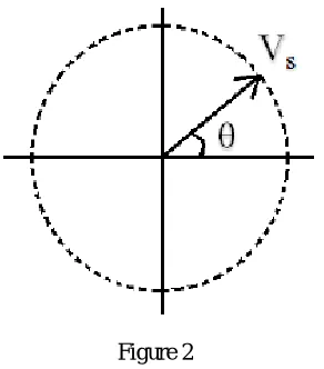
Sin
t
jCos
t
V
V
S
m
2
3
………. (4)
Vs rotates with speed
rad/Sec as represented in fig. 2Figure 2
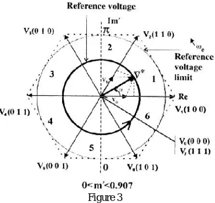
Consider a conventional 3 phase bridge VSI which has six switches, three upper and three lower; total 6 switches hence there are 8 possible combinations (0,0,0), (0,0,1),(0,1,0), (0,1,1), (1,0,0), (1,0,1),(1,1,0),(1,1,1) as shown in the table the different switching strategies for inverter[1,9,11,12]
Table 2 Different Switching Strategis
State On Device Vrn Vyn Vbn Space Voltage Vector 0 S4S6S2 0 0 0 (0,0,0) 1 S1S6S2 2Vd/3 -Vd/3 -Vd/3 (1,0,0) 2 S1S3S2 Vd/3 Vd/3 -2Vd/3 (1,1,0) 3 S4S3S2 (0,1,0) 4 S4S3S5 (0,1,1) 5 S4S6S5 (0,0,1) 6 S1S6S5 (1,0,1) 7 S1S3S5 0 0 0 (1,1,1)
Figure 3
The total harmonic distortion in space vector pulse width modulation based inverter is the ratio of the root mean square of the harmonic content to the root mean square value of the fundamental quantity, expressed as a percentage of the fundamental When the value of current have a harmonic[13,14]
100
*
/
2
rms k
I
krmsI
THD
…. …….……(5)III. CONCLUSION
This paper present review of the recent development in the area of PWM. Emphasis has been given to categorizing various PWM techniques which are reported in the literature. The paper also presented a salient feature of the various PWM. This paper will serve as a valuable resource to any future worker in this important area of research.In the view about further work based on this attempt has been going to implement through carrier based frequency & Pulse width modulation for the efficient control of induction motor drive and other allied activities. Change in modulation index fundamental frequency may get analyzed.
REFRENCES
[1] Bimal K. Bose, "Modern Power Electronics and AC Drives", Pearson Education, 2003.
[2] Muhammad H. Rashid, "Power Electronics, Circuits, Derives and applications”. Pearson Education Inc. 2004. [3] Vas, P., “Electrical Machines and Drives a Space-Vector Theory Approach,” Oxford University Press, 1992. [4] C.M. Poddar,Power Electronics Devices and Circuits,Jain Publication, 1999, 1e
[5] Joseph Vithyathil, Power Electronics , McGraw Hill Publication, 2010
[6] Keith H. Sueker, Power Electronics Design: A Practitioner’s Guide, Newnes Pub, 2005, 1e
[6] S.Prashanth, M.Santhosh, I. Rahul, Space Vector Modulation Algorithm for Multi Level Inverter, International Journal of Scientific & Engineering Research, Volume 4, Issue 6, June-2013, Pages 1980-1988
[7]Nikola Celanovic, Space Vector Modulation and Control of Multilevel Converter, Ph D Thesis,Virginia Polytechnic Institute, September 20, 2000
[8] A. Cataliotti, F. Genduso, G. RiccoGalluzzo ,A Space Vector Modulation Control Algorithm for VSI Multilevel Converters
[9] M. Nigam, A.Dubey, Design and Implementation of SVPWM Inverter are using Soft Computing, International Journal of Engineering Research & Technology Vol. 1 Issue 7, Sep. 2012
[10] Nabe, A., Takahashi, I., and Akagi, H., A new neutral-point clamped PWM inverter, IEEE Trans.Ind. Appl.17, 518, 1981.
[11] D. Sasi1, J. Kuruvilla P, Modelling and Simulation of SVPWM Inverter Fed Permanant Magnet Brushless DC Motor Drive, International Journal of Advanced Research in Electrical, Electronics and Instrumentation Engineering, Vol. 2, Issue 5, May 2013