Dual-Mode BPF with Four Transmission Zeros Using S-L Coupling
Structure with Quadratic Function Coupling Coefficient
Fei Liu, Tao Xu, Liang Sun, Yi-Fan Xue, and Hong-Wei Deng*
Abstract—In this letter, a compact microstrip bandpass filter (BPF) with four transmission zeros (TZs) is designed by using a short-stub centered loaded folded dual-mode resonator and an I/O mutual coupled open-stub loaded feedline structure. The coupling structure can realize source-load (S-L) coupling with quadratic function coupling coefficient, which can generate three TZs in the upper-stopband to improve the selectivity. Owing to the intrinsic characteristics of the dual-mode resonator, one extra TZ can be created near the lower passband edge. Finally, a compact BPF with fractional bandwidth (FBW) of 3.5% located at 2.4 GHz for WLAN application has been designed and fabricated. Good agreement between simulation and measurement verifies the validity of the design.
1. INTRODUCTION
The microstrip filters with compact size and high selectivity have found extensive applications in many RF/microwave circuits and systems. The dual-mode resonators are attractive because each resonator can be used as a doubly tuned circuit, and the number of resonators required for a given degree of filter is reduced by half, resulting in a compact filter structure [1–6]. To obtain good frequency selectivity, enhance out-of-band rejection, and minimize interference of the adjacent channels, finite TZs are critical to meet these specifications in filter design. In general, bypass-coupling, cross-coupling, and source-load-coupling topologies are widely employed to introduce finite TZs [3, 7–9]. Recently, frequency-dependent coupling that inter-resonator coupling varying linearly with frequency has been adopted to generate a designable TZ which will reduce the overall size and facilitate the implementation of high selectivity [10– 13].
In this letter, as shown in Fig. 1(a), a compact dual-mode microstrip BPF with four TZs is presented with the acute frequency-dependent S-L coupling structure. Three TZs in the upper-stopband are determined by the S-L quadratic function coupling coefficient which is realized by I/O mutual coupled open-stub loaded feedline structure. Owing to the main path signal counteraction of the dual-mode resonator, another TZ is created near the lower passband edge. Finally, a BPF with FBW of 3.5% at 2.4 GHz for WLAN application is designed and fabricated, and the measured results are in good agreement with simulated ones. Herein, the substrate is RT/Duroid 5880 with a thickness of 0.508 mm, permittivity of 2.2 and loss tangent of 0.0009.
2. PROPOSED DUAL-MODE BPF WITH FOUR TZ
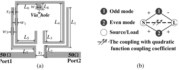
Figure 1(a) depicts the schematic layout of dual-mode microstrip BPF, which consists of the dual-mode resonator and I/O mutual coupled open-stub loaded feedline structure. The resonator is composed of a folded half-wavelength microstrip line (w1, 2(L3+L4+L5+L6)) and a short-ended stub (L8,w2). The
Received 28 July 2018, Accepted 28 September 2018, Scheduled 7 October 2018
* Corresponding author: Hong-Wei Deng ([email protected]).
Via_hole
50 Port1
50 Port2 s1
s2 L5 L6
w1 w2
L3
L4 L1
L2 L7
w3
L8
Ω Ω
S L
1
2 Source/Load
Odd mode
The coupling with quadratic function coupling coefficient
+
+ +
-1
2 Even mode
(b) (a)
Figure 1. Configuration and coupling topology of high selectivity BPF. The final dimensions of the BPF are L1 = 11.15 mm, L2 = 2.47 mm, L3 = 3.6 mm, L4 = 10.4 mm, L5 = 3.4 mm, L6 = 3.56 mm,
L7 = 4.5 mm, L8 = 2.0 mm, w1 = 0.4 mm, w2 = 0.8 mm, w3 = 0.4 mm, s1 = 0.45 mm, s2 = 0.62 mm.
(a) Configuration. (b) Coupling topology.
stub is connected at the central point of microstrip line. Since the resonator is symmetric structure, odd-even mode theory can be adopted to analyze it [1–5]. The dominant odd-mode resonant frequency
fo and even-mode one fe can be calculated as:
fo =
c
4 (L3+L4+L5+L6+w2/2)
/√
εeff
(1)
fe =
c
4 (L3+L4+L5+L6+L8)
/√
εeff
(2)
where c is the velocity of light in vacuum, andεeff is the effective permittivity. Based on the analysis in [3–5], the coupling topology scheme of the filter with the dual-mode resonator is given in Fig. 1(b). Due to the main path signal counteraction, the TZ can be created near the lower passband edge because thefo is higher thanfe
The I/O mutual coupled feedline structure is composed of two additional identically open-ended stubs (w3,L1+L7) and the mutual coupling section with lengthL2 and gaps2between two I/O feeding
lines. The direct signal path from source to load is introduced through the coupling section. Thus, one TZ can be generated owing to the extra path signal counteraction. The coupling coefficient MSL can be extracted by Equation (3) in [13].
MSL=
2
f0
Im(y12)
∂(Im(y11))/∂f
(3)
Figure 2 presents an example of S-L coupling coefficients of the I/O mutual coupled feedline structure with different geometrical parameters L1, L2 and s2. As can be seen, there are two TZs
in the frequency range from 2.5 to 5.0 GHz. Fig. 2(a) illustrates that the positions of two TZs move down as the lengthL1 increases. AsL2 decreases, the position of TZ1 moves down while the position of
TZ2 keeps almost unchanged. As depicted in Fig. 2(b), the larger thes2 is, the smaller the curvature of
the parabola is. However, the positions of two TZs change a little with the variation of s2 Because the
extracted curve of coupling coefficient exhibits a quadratic function of frequency, the form of coupling coefficient can be assumed as: k·(ω−a)·(ω−b), where ω is the normalized angular frequency and
k, a, b are constants. To distinguish this coupling with quadratic function coupling coefficient from conventional liner frequency-dependent coupling, the S-L coupling is indicated by the dash line crossed by two arrows in Fig. 1(b).
Based on the proposed coupling scheme, a BPF centered at 2.4 GHz with FBW of 3.5% is designed with the desired four TZs operating at 2.0 GHz, 2.65 GHz, 3.0 GHz, and 4.8 GHz, respectively. The obtained normalized target coupling matrix M has the following form by an optimization algorithm based on the zero-pole goal function [12]:
M =
0 0.59 0.69 −0.000022·(ω−5.4)·(ω−46)
0.59 −0.85 0 −0.59
0.69 0 0.92 0.69
−0.000022·(ω−5.4)·(ω−46) −0.59 0.69 0
2.5 3.0 3.5 4.0 4.5 5.0 -0.01
0.00 0.01
TZ1 TZ2
Frequency (GHz) C o u p li n g C o ef fi ci en t
L1=10mm L1=11mm L1=12mm
2.5 3.0 3.5 4.0 4.5 5.0 -0.01
0.00 0.01 0.02
TZ1 TZ2
Frequency (GHz) C o u p li n g C o ef fi ci en t
L2=2.5mm
L2=3.0mm
L2=3.3mm
2.5 3.0 3.5 4.0 4.5 5.0 -0.02 0.00 0.02 Frequency (GHz) C o u p li n g C o ef fi ci en t
s2=0.2mm s2=0.6mm s2=1.0mm
TZ2 TZ1
(b) (a)
(c)
Figure 2. Coupling coefficient curve of the I/O mutual coupled open-stub loaded feedline structure for different s2, L1 and L2, when w3 = 0.4 mm, L7 = 4.5 mm. (a) Different L1, when L2 = 2.5 mm.
(b) DifferentL2, when L1 = 11 mm. (c) Different s2, whenL1= 11 mm, L2 = 2.5 mm.
whereω is the normalized angular frequency.
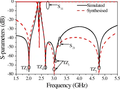
After the mode match and optimization process, the final dimensions are obtained and listed in Fig. 1. Fig. 3 gives full-wave simulated frequency responses in the frequency range from 1.5 to 5.5 GHz. Two reflection zeros and four TZs (TZ1, TZ2, TZ3, TZ4) are easily observed. The simulated frequency
responses near the passband agree well with the synthesized counterpart for the synthesis is based on the narrowband design. But there exists the difference in the out of the frequency range from 2.0 to 3.0 GHz, which may also result from the synthesized responses cannot adequately reflect the actual counterparts. For instance, the coupling coefficients between the source/load and resonator are assumed as frequency-independent.
1.5 2.0 2.5 3.0 3.5 4.0 4.5 5.0 5.5
-80 -70 -60 -50 -40 -30 -20 -10 0 Frequency (GHz) S -p ar am et er s ( dB ) Simulated Synthesised TZ 2
TZ3 TZ4 TZ1
S21 S11
1.5 2.0 2.5 3.0 3.5 4.0 4.5 5.0 5.5 -80
-70 -60 -50 -40 -30 -20 -10 0
Frequency (GHz)
S
-p
ar
am
et
er
s (
dB
)
Simulated Measured
TZ2 TZ3 TZ4
TZ1
S21
S11
(b) (a)
Figure 4. Photograph simulated and measured results of high selectivity BPF. (a) Photograph of the fabricated prototype. (b) Simulated and measured responses.
3. EXPERIMENTAL RESULTS
To validate the above design approach, the compact BPF is fabricated, and the performances are measured by Agilent network analyzer N5230C. Fig. 4 illustrates the simulated and measured responses of the BPF. The photograph of the BPF is illustrated in the inset in Fig. 4. The measured 3 dB FBW of 3.2% at 2.4 GHz with the insertion loss is 1.5 dB in the worst case and return loss better than 10 dB, still a satisfactory result. The position of the TZ1, TZ3 and TZ4 show a good agreement with the simulated
ones while the TZ2 shifts upward by approximately 120 MHz. The depicted discrepancies could be from
the effect of loss due to dielectric substrates, and finite conductivity of the metallization layers as well as the fabrication tolerance in the etching process.
4. CONCLUSION
In this letter, a compact dual-mode microstrip BPF with four TZs is presented by using the S-L coupling with quadratic function coupling coefficient. Good agreement between the simulation and measurement verifies the validity of the design.
ACKNOWLEDGMENT
This work was supported by the National Natural Science Foundation (NSF) of China under Grant 61501232, by the Fundamental Research Funds for the Central Universities under Grant NJ20160012, by the State Key Laboratory of Millimeter Waves of K201716, and by the Fundamental Research Funds for the Central Universities.
REFERENCES
1. Hong, J. S., H. Shaman, and Y. H. Chun, “Dual-mode microstrip open-loop resonators and filters,” IEEE Trans. Microw. Theory Tech., Vol. 55, No. 8, 1764–1770, 2007.
2. Deng, H. W., Y. J. Zhao, X. S. Zhang, W. Chen, and J. K. Wang, “Compact and high selectivity dual-band dual-mode microstrip BPF with single stepped-impedance resonator,” Electron. Lett., Vol. 47, No. 5, 326–327, 2011.
3. Zhou, M. Q., X. H. Tang, and F. Xiao, “Miniature microstrip bandpass filter using resonator-embedded dual-mode resonator based on source-load coupling,” IEEE Microw. Wireless Compon. Lett., Vol. 20, No. 3, 139–141, 2010.
5. Gao, S., S.-Q. Xiao, and J.-L. Li, “Miniaturized microstrip dual-mode filter with three transmission zeros,” Progress In Electromagnetics Research Letters, Vol. 31, 199–207, 2012.
6. Feng, W., X. Gao, and W. Che, “Bandpass filters with improved selectivity based on dual-mode ring resonators,” Progress In Electromagnetics Research Letters, Vol. 56, 1–7, 2015.
7. Xu, Z., Y. Shi, C. Xu, and P. Wang, “A novel dual mode substrate integrated waveguide filter with mixed source-load coupling (MSLC),” Progress In Electromagnetics Research, Vol. 136, 595–606, 2013.
8. Zhang, X.-S., Y.-J. Zhao, H.-W. Deng, L. Zhang, and W. Chen, “High selectivity dual-mode bandpass filter with source-loaded coupling,” Progress In Electromagnetics Research Letters, Vol. 18, 187–194, 2010.
9. Tamiazzo, S. and G. Macchiarella, “Synthesis of cross-coupled prototype filters including resonant and non-resonant nodes,”IEEE Trans. Microw. Theory Tech., Vol. 63, No. 10, 3408–3415, 2015. 10. Leszczynska, N., L. Szydlowski, and M. Mrozowski, “A novel synthesis technique for microwave
bandpass filters with frequency-dependent couplings,” Progress In Electromagnetics Research, Vol. 137, 35–50, 2013.
11. Hsu, C.-L. and J.-T. Kuo, “Microstrip realization of trisection synthesis with frequency-dependent admittance inverter,” Progress In Electromagnetics Research, Vol. 113, 195–210, 2011.
12. Szydlowski, L., A. Lamecki, and M. Mrozowski, “Coupled-resonator waveguide filter in quadruplet topology with frequency-dependent coupling — a design based on coupling matrix,”IEEE Microw. Wireless Compon. Lett., Vol. 22, 553–555, 2012.