Improvement of Power Quality of Microgrid by Using Improved
Droop Controller for Reactive Power Sharing
Tavva Ravisankar Reddy
1, Kurakula Vimala Kumar
2, Thalluru Anil Kumar
3 1M.Tech Student,
2Assistant Professor,
3Professor
1,2Dept. of EEE, JNTUA College of Engineering, Pulivendhula, Andhrapradesh, India 3
Dept. of EEE, CVSR College of Engineering, Hyderabad, Telangana, India
Abstract
Due to the rapid growth in the electricity demand as well as fossil fuels reduction, and the constabularies of government on the greenhouse gas emission mitigation, modalities of renewable energy are more enchanting and several types of distributed generation sources such as solar photo voltaic (PV) panels and wind turbine generators are being associated to the distribution networks those are low-voltage. Micro grid is a unified system that consists management of loads, control systems, distributed generation sources, storage of energy and communication infrastructure capability to work in both grid connected and island mode to optimize energy usage. In this, our proposed implementation mainly concentrates on two vital operations, named as mitigation of error operation and recovering of voltage operation. The precision of sharing has been enhanced by the sharing error mitigation approach, which is triggered by the synchronized signals with the less bandwidth. However, this approach leads to the diminishment in the amplitude of output voltage. Hence, the second operation is proposed to recover the diminished voltage amplitude. The paper presents a advanced control technique for a micro grid system which works efficiently under a decentralized control system.
Keywords: Microgrid, Renewable energy resource, Distributed generation, Droop control
1.
Introduction
Petroleum derivative stores will vanish sooner rather than later, so individuals should discover elective vitality sources to keep away from this debacle. Expanded worries rising cost regular vitality (e.g. petroleum derivative) natural
effects quick moving concentration utilization of
inexhaustible feasible vitality sources. Utilization of sustainable power sources getting noticeably well known alongside petroleum products consumption. The flighty and discontinuous nature of sustainable power sources have shielded them from coordinating with the utility matrix. The use of disseminated age has been increasing quickly previous decades. Contrasted with the conventional brought together power age, DG units have advantages of less contamination, higher effectiveness of vitality utilization, more adaptable establishment area, and less power transmission losses. A large portion of the DG units associated with lattice by means energy electronic converters, which presents
framework reverberation, protection interference, forth. To surmount these issues, microgrid concept Solution. Compared to utilize a solitary DG unit, microgrid could offer unrivaled power management inside the dispersion systems. In addition, the microgrid can work network associated mode islanded mode and advantage both heap control More often than not, the droop control technique which impersonates conduct synchronous generator in customary power framework is received, which does not require the utilization of basic communications. Dynamic power sharing constantly accomplished by droop control strategy effortlessly. In any case, because of impacts of mismatched feeder impedance between the DGs burdens, the reactive
power won't be shared precisely. In outrageous
Advantages:
Cost effective and practical approach Reduction in reactive power sharing error
Robust delay in communication
2.
Distributed Generation
2.1 Background
Dispersed alternator characterized vitality power source associated dissemination arrange or straightforwardly client
application. Because expanding load prerequisites
framework venture extensive incorporated power plants require, an investigation framework fundamentally affect stream of energy and toward the end clients. A microgrid can make a little hearty framework using a large number of these appropriated age units by utilizing neighborhood data every generator. Micro grids offer many points of interest over the
conventional concentrated electrical framework.
Concentrate work is on the power dependability that dispersed age combined idea can accomplish.
Fig1: Microgrid power system
2.2 Applications of Distributed Generation
There are numerous applications that require an abnormal state of dependability and power electrical foundation. Conventional applications incorporate move down power gadgets for the media communications industry however the idea can be extended to fiasco help endeavors, national protection applications and whenever there is an absence of a focal electrical foundation. While a media communications organize has a never-fall flat prerequisite, different applications may have diverse targets and exceptional difficulties. Reaction time is short fiasco help endeavors and almost no site building should be possible ahead conveyance arrange. Capacity make framework effortlessly small
building would give adaptability to include generators and loads as the alleviation exertion advanced. In meantime, this framework ought to likewise give vitality to basic structures, example, and field clinics correspondence focuses. Division of Defense applications has another arrangement of special difficulties that require a versatile, powerful dependable electrical system. A huge army base resembles a city unto itself containing malls, film theaters and living quarters for a huge number of individuals. Regularly such an establishment has few give energy base. makes establishment's central goal extremely traded off if the power supply from feeder lines is hindered for normal alluring establishments had a versatile power framework that would identify flimsiness framework using a controller that would enable the framework to assimilate hose impacts unsettling influences maintaining a strategic distance from an aggregate framework fall. Combined with need clever such a framework would safeguard, to the point power is conveyed basic burdens keeping in mind that keeping the establishment condition of status.
3.
Control Of Microgrid
3.1Control methods for distributed Generation within Microgrid
Additional load demands are chosen by energy sources distributed and therefore intended to be loaded to utility grid. With this configuration, distribution of load that appears from benefit of allowing the microcontroller to handle demand-side loads. Third Configuration is one of previous two is a hybrid, with some sources that control power into MG. Configuration, some units work efficiency, and ensures that other units are stable in situations where current flow from grid current.
3.2 Previous Works Involving the Control of Micro grids
Droop control scheme for parallel inverters is used to connect Proximity operation of method proposes a frequency droop using a master slave connection and loading partnership between distant groups. Master Inverter uses regular recursive voltage control, suppressing harmonic distortion and slave inverter uses recurrent control in current mode. Proposed modify droop feature, which is thus increasing at nodes with a large local load, thus reducing electrical exchange through distribution system from traditional droop schemes. Simulation results show that this hybrid control configuration improve wave reduction of distortion. However, complexity of the master slave relationship and voltage controller creates a unique controller an application. DG sources to MC, permitting island mode operation and grid connected operation. Droop equations are performed by controlling an electrical electronic inverter perform voltage source with the virtual resistive-predicative output impedance.Another met offer a voltage power droop frequency-reactive power boost control scheme, which allows current, controlled VSC to work parallel to same MC. Each VSC in MG has its own controller, its current instructions control the voltage and frequency of a simple MG bus to track dropped references. Control scheme provides voltage and frequency control of MG in ideal mode, providing VSC's current protection, only one 3-step input in VSC output interface. The controller has a change in multiple PI loops and d-q reference frame. The results of the above method are the joint control of voltage and real and reactive power sharing DC. Space Vector PWM algorithm looking for investor controls in a stand-alone system. The advantage of using a voltage vector is that the basic voltage magnitude controls reactive power and the vector's angle can used monitor frequency of inverter output. The voltage vector can be obtained from local information, eliminating need for a communication code between sources. One potential problem scheme uses maximum frequency, which limits the range of applications used. Faults systems with realistic and distributed generators are not exempt in any electrical distribution system. A controller is required to maintain sustainability and provides a regulatory framework for investors to maintain controlled product voltages during system voltage irregularities from system defects. The controller maintains voltage at the sensitivity levels of
devices, generators are in ideal mode, providing real and reactive power-flow controls while working in grid-tied mode. The controller filter indoor current uses a filter capacitor voltage multiple loops that contain regulators for real and reactive forces. Simulation results have been shown study, regulator confirmed that it works in both grid-tide and island mode. The frequency control is not discussed in this work controller is designed in a frequency that does allow use of droop control in frequency. Another method of analysis of droop-based generation control schemes for product waves delivered by using traditional real power-frequency reactive power-voltage coupling control. It develops small-signal patterns with many DG sources in radial networks. Generator radial network with loads and loaded with an infinite bus at each distribution source bus. The system's matrix MG will be sent into sub matrices indicating streams. And adequate conditions have been developed ensure their small signal stability, and guidance has been given to the design of active power-frequency and reactive power-voltage controllers. Analysis of line pharos dynamics improves the stability of a grid with DGs exceeding traditional droop control. Assuming generators on electrical system, PWM output filters are considered to be an ideal voltage source three-step VSI, generator controlled frequency and voltage. If a low pass filter is included on output to reduce harmonics, frequency control system is a sample of rotating generator that is similar to inertia dumping torque, which depends on the benefit of two times. Because adjustment of frequency of low pass filter, the root position plots indicate that it is usually difficult to get stable behavior larger duplex gains. The authors provide a compensation based on the Line phase model that introduces an additional three parameters allows the controller design voltage and frequency when determining their stability. Over the simulations in the project show develop stability improved performance time settlers.
3.3 Droop Control
Rotation speed, direct frequency, decreases, indicates torque improvement. Torque increases without increase main torque. Slowing frequency with increased load attempts to control droop achieve controlled stable manner.
3.4 Power Sharing in Microgrid
used to achieve the goal of active power. According to this method, the present value of each SG's rotational speed on the network exceeds production of the energy required to provide SG. Investigators have proposed to investigate similar control of AC inverter, as it stimulates. This is shown for loss less MGs and Networks. This heuristic objective decentralization regulation Act actually stabilizes network frequency and control gains and set areas are selected, with clear communication between fixed different sources with none of the desired reactivity distribution. The unwanted clear communication system is explained by the fact that the
network frequency works as a normal internal
communications signal. Since the actuator signal of this control is a local frequency, it is called frequency droop control in the presentation of the project. Furthermore, in large transmission systems, droop control is generally applicable only to obtain the desired active power distribution, but voltage penetration at the generator bus controls nominal voltage setting by AVR in the activated system of SG. Electric lines are relatively small in MGs. Then, in AVR voltage expansions that operate at the transmissible level, it is generally not enough to provoke higher reactive power flows from slight deviations. Hence, droop regulation is typically intended to achieve the required reactive power distribution in MG for voltage. The most common mechanism is to set voltage distribution through a proportional control.
3.5 Proposed Method for Control of Micro Grid
3.5.1 Configuration of The Proposed Microgrid
The classic configuration of MG that contains multiple PCC is connected to microprocessor using static transfer switch. Each DG unit is connected to the MG through the electrical and electronic converter and its corresponding feeder.
Fig2: Configuration of micro grid
3.6 LC Filter
An LC circuit is a resonant circuit or tune circuit that consists of an inductor, represented by the letter L, and a capacitor, represented by the letter C. When connected together, an electric current can alternate between them at the circuit's resonant frequency. LC circuit used either for generating signals at a particular frequency or picking out a signal at particular frequency from a more complex signal. They are key components in many applications such as oscillators, filters, tuners and frequency mixers. An LC circuit is an idealized model once it assumes there is no dissipation of energy due to resistance.
Operation: An LC circuit can store electrical energy vibrating at its resonant frequency. A capacitor stores energy in the electric field between its plates, depending on the voltage across it, and an inductor stores energy in its magnetic field, depending on the current through it.
Fig3: LC Filter
If a charge capacitor is connected to an inductor, the charge flows through inductor, surrounding it by building a magnetic field, and reducing the voltage on the capacitor. Eventually the charge on the capacitor has gone and the voltage will reach zero. Nevertheless, it is currently undergoing, because current inductions block current changes, and it captures energy from the magnetic field to make it flow, which starts to decline. The electric charge begins to charge the capacitor with a voltage opposite to its original charge. When the magnetic field is completely lost, the current is deactivated and the charge is again stored in the capacitor, the previous inner polarity. Then the cycle starts again, the current flowing through the opposite direction by electricity. The charge flows back and forth between the capacitor's plates, by the electric conductor. The power between the capacitor and the inductor swings back of internal resistance. Its action is mathematically known as a harmonic oscillator, which resembles a pendulum on the back and forward, or water backwards. For this reason the circuit is also called a tank circuit. Used capacitance and inductive values determine the frequency of anxiety. In normal tuned circuits in electronic devices, oscillations are very fast, Time Domain Solution:
By KVL law: By KCL law:
From the constitutive relations for the circuit elements:
The Second Order Differential Equation: i(t)=0
3.7 Conventional Droop Control Method
Equivalent circuit model of a DG unit is as shown in Fig.3.7, which is linked to common bus of MG through a power inverter in addition with output LCL filter.
Fig4: Model of DG unit
∟ indicates voltage across filter capacitor, and Vpcc∟0◦ is common ac bus voltage. Inductance of LCL filter Compared with the line resistance is ignored. Then, impedance between inverter and common bus can be described as Xi (Xi = ωLi). Based on equivalent circuit, the inverter output apparent power is Si, and it can be written as
………..(3.7.1)
DG is regulated by and voltage amplitude output respectively. Then, the conventional droop control is given by
} …….…..(3.7.3)
4.
Proposed Reactive Power Sharing Error
Compensation Method
The proposed droop control method is given as follows …….(4.1)
…………..(4.2)
where k means season synchronization occasion until time t. As indicated by (4.2), the control is a mixture framework with ceaseless and discrete qualities. In the computerized execution of the proposed strategy, the nonstop variables Ei(t) and Qi(t) are discretized with examining period Ts , and Ts is incredibly not as much as the time interim between two successive synchronization occasions. In this manner, the hang (4.2) at the kth synchronization interim communicated as
……….(4.3)
where ω^*and E^*are estimations recurrence yield voltage an abundance at no heap condition; mi and ni are the hang increases of recurrence interim, Gn has two conceivable esteems: 1 or 0. On the off chance that Gn= 1, it means the voltage recuperation operation is performed. Q_i^n represents the output responsive energy synchronization interval. Kiis a remuneration coefficient for the DG-I unit, ΔE is a consistent incentive for voltage recuperation. For simplicity of portrayal, the third term of (4.3) is alluded to the sharing error decrease operation, and the last term is known as the voltage recuperation
………….(4.4)
Thusly, for its execution, just E_i^(k-1)andQ_i^(k-1)should be put away in DSP. To better comprehend the proposedmethod, a particular illustration is given. In the event that there are two DG unitswith a similar limit working in parallel, and the conventionaldroop is just utilized. responsive power sharingerror because of a few components. In the event that the sharing mistake lessening operationfor every the subsequent reactivepower sharing blunder will
diminish. The standard behind thesharing mistake
diminishment operation can be comprehended with the aidof figure demonstrated as follows
Fig5: Schematic diagram of sharing error reduction operation
Fig6: Schematic diagram of voltage recovery mechanism
4.1 Communication Setup
Every Daunt has chance to trigger synchronization occasion on the condition that the time interim sequential occasions is more noteworthy than a passable least esteem and the yield voltage of each DG unit is in the sensible range. On the off chance that the yield not as much as its permitted low point of confinement, it will request need to trigger a synchronization occasion immediately. Until the limitation interim between two successive synchronization occasions is more prominent than an allowable minimum value is fulfilled, the DG unit with the need will trigger synchronization occasion, and in this occasion, the charge for voltage recuperation. Off chance that the correspondence comes up short (the time interim between two sequential synchronization occasions is more prominent than a passable maximum value), all the mistake diminishment technique returns to the ordinary one. As indicated by the previously mentioned investigation, such a microgrid framework just needs a low bandwidth correspondence. Furthermore, it is robust the postponement of correspondence. To represent
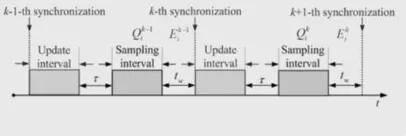
Fig7:Controltimingdiagram of one DG withtwo consecutivesynchronisation events
The sharing mistake recuperation operation is performed in refresh interim. Testing operation happens in inspecting interim. There is a period interim which is sufficiently long to ensure the framework being in relentless state. Clearly proposed technique is hearty since important operations just should be finished interim, not a basic point.
4.2 Convergence Analysis
Proposed strategy proved. Without loss of all inclusive statement, the sharing responsive power blunder between-I
and DG-j with a similar limit broke down. As indicated by (4.3), the receptive hang condition for communicated as
…………..(4.2.1) Subtracting(4.3.1) from (4.3)
………..(4.2.2)
....…………..(4.2.3)
Where According to the contraction mapping
algorithm, |r| <1 and
ΔX = 0then responsive power sharing mistake will join to zero. For the most part, ΔX ≠ 0, we ought to likewise consider the impact of the second term of (4.2.3).
As per the feeder trademark, we have
………..(4.2.4)
Voltage recovery mechanism, ensures Emin for
all k
………(4.2.11)
Therefore thesecondterm of (4.2.3) is bounded.
Accordingaforesaidanalysis, it couldbe concluded thatthe reactive powersharingerror is alsobounded.
5.
Simulation Modeling & Results
5.1 Proposed simulation diagrams A. Proposed Droop Controller
The proposed enhanced responsive vitality distorting methodology confirmed analysis. The related recorded in Table I. Also, keeping in mind the end goal to encourage the perception of the responsive receptive forces
Fig8: Proposed simulation diagram
Fig9:Proposed Control Diagram
Controlling of simulation diagram is performed for the following three cases
1. Power sharing accuracy improvement 2. Effect of Communication delay 3.Effect of Load Change
5.2 Simulation results
Case-1:PowerSharingAccuracyImprovement
Two identical DG units work voltage droop control.
Fig. 5.2.1 shows the responsive power sharing performance of the two DGs. Before t=0.5s the sharing error education recuperation disabled, which is proportionate to the regular hang control being in effect. There exists a conspicuous responsive power sharing blunder due to the unequal voltage drops on the feeders. After t =0.5 s, there active blunder lessening performed, and obviously the responsive power sharing mistake unites to zero step by step. After t = 1 s, the voltage recuperation operation is performed. It can be watched that the yield receptive power increases however the responsive power sharing execution does not debase.
Q/Var
t/s
Fig10: Output reactive powers of two inverters with the improved droop control.
U0/V
t/s
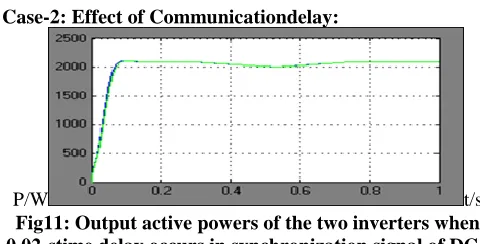
Case-2: Effect of Communicationdelay:
P/W t/s
Fig11: Output active powers of the two inverters when 0.02-stime delay occurs in synchronization signal of DG1
unit. Case-3:Effectof Loadchange
Keeping in mind the end goal to test the impact of load technique, the dynamic load increases about 1.6 kW and the receptive load increments around 0.4 k Var at t = 2.5 s, and at t = 4.5 s the dynamic load diminishes about3.0 kW and the responsive load diminishes around 0.8 kVar.
U0/V
t/s
Fig12: DG output voltage of the improved droop control (with load changing)
6.
Conclusion
In this task, another receptive power managing for enhancing responsive dispatch proposed for control hardware interfaced DG units in air conditioning micro grids. Proposed control technique acknowledged accompanying dispatch mistake decrease operation voltage recuperation operation. Main work changes voltage predisposition ordinary hang trademark bend occasionally, which is actuated by the transmission synchronization signals. The second operation is performed to reestablish the yield voltage to its evaluated esteem. The enhanced power sharing can be accomplished exceptionally basic interchanges. Besides, attachment highlight of every DG unit won't be influenced. The reenactments comes about are given to confirm the viability of the proposed control technique.
References
[1] Jinwei He and Yun Wei Li, An Enhanced Micro grid Load Demand Sharing Strategy, IEEE-2012.
[3] Y. Li and Y. W. Li, Power management of inverter interfaced autonomous microgrid based on virtual frequency-voltage frame, IEEE Trans. Smart Grid., vol. 2, no. 1, pp. 30–40, Mar. 2011.
[4] C.-T. Lee, C.-C. Chu, and P.-T. Cheng, A new droop control method for the autonomous operation of distributed energy resource interface converters, in Proc. Conf. Rec. IEEE Energy Convers. Congr. Expo., Atlanta, GA, 2010, pp. 702–709.
[5] J. M. Guerrero, L. G. Vicuna, J. Matas, M. Castilla, and J. Miret, Output impedance design of parallel-connected UPS inverters with wireless load sharing control, IEEE Trans. Ind. Electron., vol. 52, no. 4, pp. 1126–1135, Aug. 2005.
[6] Y. W. Li and C.-N. Kao, An accurate power control strategy for power electronics- interfaced distributed generation units operation in a low voltage multibus microgrid, IEEE Trans. Power Electron., vol. 24, no. 12, pp. 2977– 2988, Dec. 2009.
[7] J. He and Y. W. Li, Analysis, design and implementation of virtual impedance for power electronics interfaced distributed generation, IEEE Trans.Ind. Appl., vol. 47, no. 6, pp. 2525–2538, Nov./Dec. 2011.
[8] E. A. A. Coelho, P. C. Cortizo, and P. F. D. Garcia, Small-signal stability for parallel-connected inverters in stand-alone AC supply systems, IEEE Trans. Ind. Appl., vol. 38, no. 2, pp. 533–542, Mar./Apr. 2002.
[9] Y. W. Li, D. M. Vilathgamuwa, and P. C. Loh, Design, analysis and real- time testing of a controller for multibus microgrid system, IEEE Trans. Power Electron, vol. 19, no. 5, pp. 1195–1204, Sep. 2004.
[10]L.V Narasimha. "Power Quality Improvement in a Grid Connected PV Cell using UPQC with Fuzzy Logic Controller.", International Journal gor Modern Trends in Science and Technology, Vol 2, no.2, pp.31-37, Feb 2016. [11]M. Sudhakar Babu, and S. Rajasekhar. "ANFIS Based UPQC for Power Quality Improvement.", International Journal for Modern Trends in Science and Technology, Vol 2, no.5, pp. 6-10, May 2016. (2016).