Experimental Investigation and Optimization
of Process Parameters of Electrical Discharge
Machining with H13 Steel
Ranjith.R1, Rakesh.N2
PG Student,Department of Mechanical Engineering, Sri Krishna College of Engineering and Technology, Coimbatore,
Tamilnadu, India1
Assistant Professor, Department of Mechanical Engineering, Sri Krishna College of Engineering and Technology,
Coimbatore, Tamilnadu, India2
ABSTRACT: H13 steel is well known for its high strength to weight ratio along with high corrosive resistance makes it inevitable application in the field of automobile and aeronautical industries. Electrical Discharge Machining (EDM) is used to machine the ‘hard-to-cut’ materials which are not machined by traditional methods. In this method an attempt is made to optimize the output parameters such as surface roughness (Ra), material removal rate (MRR), and tool wear rate (TWR) by varying the input parameters such as peak current (Ip), pulse on (Ton) time and pulse off (Toff) time. Response Surface Methodology (RSM) is applied to design the number of experiments and the experimental results are to be analyzed using analysis of variance (ANOVA) to find out significant contribution of machining parameters over responses and the optimal combinations of the parameters are determined.
KEYWORDS: H13 steel, Ra, MRR, TWR, Ip, Ton, Toff, Response Surface Methodology, Analysis of variance
І.INTRODUCTION
Electrical discharge machining (EDM), sometimes colloquially also referred to as spark machining, spark eroding, burning, die sinking, wire burning or wire erosion, is a manufacturing process whereby a desired shape is obtained using electrical discharges (sparks). Material is removed from the workpiece by a series of rapidly recurring current discharges between two electrodes, separated by a dielectric liquid and subject to an electric voltage. One of the electrodes is called the tool-electrode, or simply the "tool" or "electrode", while the other is called the workpiece-electrode, or "workpiece”. When the distance between the two electrodes is reduced, the intensity of the electric field in the volume between the electrodes becomes greater than the strength of the dielectric (at least in some point(s)), which breaks, allowing current to flow between the two electrodes. This phenomenon is the same as the breakdown of a capacitor (condenser). As a result, material is removed from both electrodes. Once the current stops (or is stopped, depending on the type of generator), new liquid dielectric is usually conveyed into the inter-electrode volume, enabling the solid particles (debris) to be carried away and the insulating properties of the dielectric to be restored. Adding new liquid dielectric in the inter-electrode volume is commonly referred to as "flushing". Also, after a current flow, the difference of potential between the electrodes is restored to what it was before the breakdown, so that a new liquid dielectric breakdown can occur.
II. EXPERIMENTAL WORK
In this work H13 hot work tool steel is used for the experimentation. H13 hot work tool steel has high tensile strength, wear-resistance and toughness with good thermal conductivity and insensitiveness to hot cracking. H13 type grade offers a good resistance to softening, up to 600ºC, combined with good stability in hardening and high toughness, making it suitable not only for hot die applications but also plastic moulds. It have many application for making hot punches and dies for blanking, bending, swaging and forging, hot extrusion dies for aluminium, cores, ejector pins, inserts and nozzles for aluminium, tin and lead die casting. In this work H13 tool steel plate of 100mm x 100mm x 8mm is used for experimentation.
Table 1: H13 tool steel composition
Element C Mn S Si Cr V Mo P Fe
% 0.316 0.338 0.0134 0.8025 4.956 1.09 1.285 0.0125 Remaining
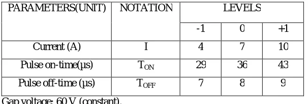
In this experimental study, it was decided to study the effects of current, pulse on time and pulse off time on process performance keeping voltage as constant. Based on earlier studies, trial conditions, the range of input parameters was decided as in Table 2. In selecting an appropriate orthogonal array, the pre-requisites are (i) selection of process parameters and interactions to be evaluated and (ii) selection of number of levels for the selected parameters.
Table 2: Controllable parameters and their levels
PARAMETERS(UNIT) NOTATION LEVELS
-1 0 +1
Current (A) I 4 7 10
Pulse on-time(µs) TON 29 36 43
Pulse off-time (µs) TOFF 7 8 9
Gap voltage: 60 V (constant).
Evaluation of response parameters
The MRR is expressed as the ratio of the difference of weight of the workpiece before and after machining to the machining time.
MRR = (Wjb-Wja)/t
whereas Wjb = Weight of the job before machining. Wja = Weight of the job after machining. t = Machining time
TWR is expressed as the ratio of the difference of weight of the tool before and after machining to the machining time.
TWR = (Wtb-Wta)/t
whereas Wtb = Weight of the tool before machining. Wta = Weight of the tool after machining.
t = Machining time
III. RESULTS AND DISCUSSION
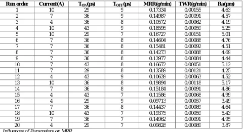
Table 3 shows the response values for MRR, TWR and surface roughness along with the input factors.
Table 3: L20 orthogonal array with multi-response values
Run order Current(A) TON(µs) TOFF(µs) MRR(g/min) TWR(g/min) Ra(µm)
1 10 29 9 0.17334 0.00155 4.63
2 7 36 9 0.14987 0.00091 4.57
3 4 36 8 0.10572 0.00062 4.19
4 10 43 9 0.18595 0.00059 5.25
5 10 29 7 0.16727 0.00151 5.01
6 7 36 8 0.14604 0.00088 4.76
7 7 36 8 0.15481 0.00092 4.51
8 7 36 8 0.14273 0.00088 4.69
9 7 36 8 0.13977 0.00084 4.44
10 7 43 8 0.16672 0.00051 5.12
11 7 29 8 0.13589 0.00121 4.25
12 4 43 9 0.10639 0.00063 4.52
13 10 36 8 0.19894 0.00118 5.17
14 7 36 8 0.15184 0.00091 4.86
15 4 43 7 0.11586 0.00068 4.99
16 4 29 9 0.09713 0.00057 3.49
17 7 36 8 0.14437 0.00089 4.64
18 10 43 7 0.19375 0.00059 5.43
19 7 36 7 0.14962 0.00091 4.95
20 4 29 7 0.09828 0.00089 3.87
Influences of Parameters on MRR
Figure 1: Effect of input parameters on MRR
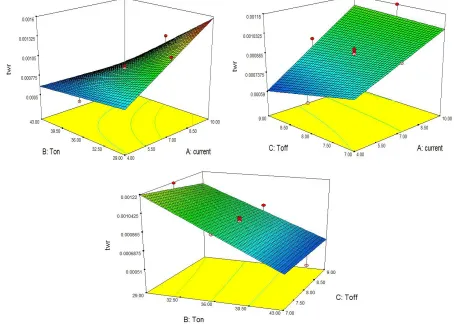
Influences of Parameters on Tool Wear Rate
The effects of the each input parameter on Tool Wear Rate (TWR) are discussed, where the combined effects of the input parameters on Tool Wear Rate are represented in graphs, which clearly shows that increase in current increases the Tool Wear Rate and increase in pulse on time decreases Tool Wear Rate and pulse off time not showing a greater influence over TWR. Combined effect of input parameters on TWR is represented in graphs.
Influence of Parameters on Surface Roughness
The effects of the each input parameter on Surface Roughness (Ra) are discussed, where the combined effects of the input parameters on Surface Roughness are represented in graphs, which clearly shows that increase in current increases the Surface Roughness and also in the same manner increase in pulse on time increases the Surface Roughness and increase in pulse off time decreases the Surface Roughness. Combined effect of input parameters on Surface Roughness is represented in graphs.
Figure 3: Effect of input parameters on Surface Roughness.
IV. CONCLUSION
The following conclusions are made based on the results and discussion for the H13 steel material with copper electrode:
From the combined effects of the parameters, it is studied that MRR increases with increase in current and pulse on time and pulse off time didn’t show significant contribution.
The TWR increases with increase in current and decreases with increase in pulse on time whereas pulse off time didn’t show significant contribution.
Surface roughness increases with increase in current and pulse on time and decreases with pulse off time.
REFERENCES
[2] Gurtej Singh, Paramjit Singh, Gaurav Tejpal, Baljinder Singh ‘Effect of machining parameters on surface roughness of h13 steel in edm process using powder mixed fluid’ International Journal of Advanced Engineering Research and Studies E-ISSN2249–8974.
[3] Paulo Pecas, Elsa Henriques ‘Effect of the powder concentration and dielectric flow in the surface morphology in electrical discharge machining
with powder mixed dielectric (PMD-EDM)’ Int J Adv Manuf Technol (2008) 37:1120–1132.
[4] P. Pecas, E. Henriques ‘Electrical discharge machining using simple and powder-mixed dielectric: The effect of the electrode area in the surface roughness and topography’ journal of materials processing technology 200 (2008) 250 258.
[5] D.K.Aspinwall, R.C. Dewes, H.G. Lee, J. Simao ‘Electrical Discharge Surface Alloying of Ti and Fe Workpiece Materials Using Refractory Powder Compact Electrodes and Cu Wire’.
[6] P.Pecas, E.Henriques ‘Influence of silicon powder-mixed dielectric on conventional electrical discharge machining, International Journal of Machine Tools & Manufacture 43 (2003) 1465–1471.
[7] Jia Tao, Albert J. Shih, Jun Ni ‘Near-Dry EDM milling of Mirror-Like surface finish’ International Journal of Electrical Machining, No.13, January 2008.
[8] Anirban Bhattacharya, Ajay Batish, Gurmail Singh, V. K. Singla ‘Optimal parameter settings for rough and finish machining of die steels in
powder-mixed EDM’ Int J Adv Manuf Technol (2012) 61:537–548.
[9] Naveen Beri, Anil Kumar ‘Optimisation of electrical discharge machining process with CuW powder metallurgy electrode using grey relation theory’ Int. J. Machining and Machinability of Materials, Vol. 9, Nos. 1/2, 2011.
[10] A Bhattacharya, A Batish, G Singh ‘Optimization of powder mixed electric discharge machining using dummy treated experimental design with analytic hierarchy process’ Journal of Engineering Manufacture 2012 226: 103.
[11] Naveen Beri, S.Maheshwari, C.Sharma, Anil Kumar ‘Performance Evaluation of Powder Metallurgy Electrode in Electrical Discharge Machining of AISI D2 Steel Using Taguchi Method’ International Journal of Mechanical, Aerospace, Industrial, Mechatronic and Manufacturing Engineering Vol:2, No:2, 2008.
[12] Anil Kumar, Sachin Maheshwari, Chitra Sharma, Naveen Beri ‘Research Developments in Additives Mixed Electrical Discharge Machining (AEDM): A State of Art Review’ Materials and Manufacturing Processes, 2013.
[13] Ajay Batish, Anirban Bhattacharya, V. K. Singla, Gurmail Singh ‘Study of Material Transfer Mechanism in Die Steels Using Powder Mixed Electric Discharge Machining’ Materials and Manufacturing Processes, 27: 449–456, 2012.
[14] Sarabjeet singh sidhu, Ajay batish, Sanjeev kumar ‘Study of Surface Properties in Particulate-Reinforced Metal Matrix Composites (MMCs) Using Powder-Mixed Electrical Discharge Machining (EDM)’ Materials and Manufacturing Processes, 29: 46–52, 2014.