Abstract
STUBBLEFIELD, RASHONDA KIAM. Extensional Tectonics at Alba Mons, Mars: A Case Study for Local versus Regional Stress Fields. (Under the direction of Dr. Paul K. Byrne). Alba Mons is a large shield volcano on Mars, the development of which appears to be
responsible for tectonic landforms oriented radially and circumferentially to the shield. These landforms include those interpreted as extensional structures, such as normal faults and systems of graben. These structures, however, may also be associated with broader, regional stress field emanating from the volcano-tectonic Tharsis Rise, to the south of Alba Mons and centered on the equator. In this study, I report on structural and statistical analyses for normal faults proximal to Alba Mons (in a region spanning 95–120° W and 14–50° N) and test for systematic changes in fault properties with distance from the volcano and from Tharsis. A total of 11,767 faults were mapped for this study, and these faults were all measured for strike, length, and distance from Alba Mons and Tharsis. Additional properties were qualitatively and quantitatively analyzed within a subset of 62 faults, and model ages were obtained for two areas with crater statistics. Distinguishing traits for each structure
region. Faults that are circumferential and radial to Alba Mons are likely primarily associated with a local, volcano-related stress field. Faults that are radial to Tharsis are primarily
Extensional Tectonics at Alba Mons, Mars: A Case Study for Local versus Regional Stress Fields
by
Rashonda Kiam Stubblefield
A thesis submitted to the Graduate Faculty of North Carolina State University
in partial fulfillment of the requirements for the degree of
Master of Science
Marine, Earth, and Atmospheric Sciences
Raleigh, North Carolina 2018
APPROVED BY:
________________________ _______________________ Dr. Paul K. Byrne Dr. Karl W. Wegmann Committee Chair
ii
Dedication
iii
Biography
iv
Table of Contents
List of Tables ...v
List of Figures ... vi
Chapter 1: Introduction, Background, and Overview ...1
Geological setting ...1
Normal faults and graben ...5
History of Mars data ...6
Previous Alba Mons work ...7
Study rationale ...14
Chapter 2: Methods ...15
Data ...15
Study areas ...16
Mapping methods and techniques ...17
Analyses for all mapped faults ...18
Fault analysis ...19
Crater statistics analysis ...20
Chapter 3: Results...20
Study region results...21
Study area results ...26
Study fault results by study area ...37
Study fault results collectively ...43
Crater statistics results ...44
Chapter 4: Discussion ...48
All faults...48
Study faults ...60
Cratering statistics ...67
Chapter 5: Conclusions ...69
v
List of Tables
Table 1 Study areas in this study. ...16
Table 2 Number of faults, mean fault strike, and standard deviation for all structures mapped in this study. ...22
Table 3 Total faults, mean fault strike, and standard deviation of fault strike by geological unit. ...23
Table 4 Results for selected faults in the “Tantalus North" study area. ...34
Table 5 Results for selected faults in the “Tantalus South” study area. ...36
Table 6 Results for selected faults in the “Ceraunius North” study area. ...36
Table 7 Results for selected faults in the “Ceraunius South” study area. ...37
Table 8 Results for selected faults in the “Tractus” study area. ...37
vi
List of Figures
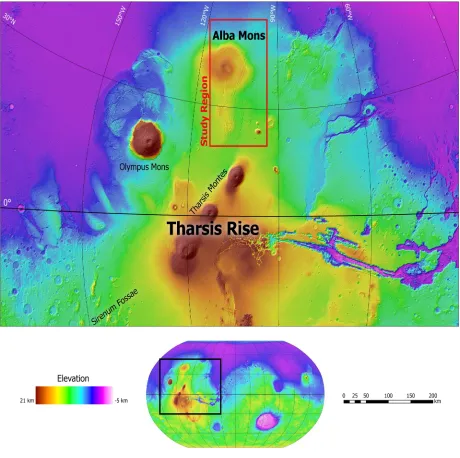
Figure 1 The Tharsis Rise on Mars, a broad, elevated dome situated at the planet’s
equator and host to the largest volcanoes in the Solar System. ...2
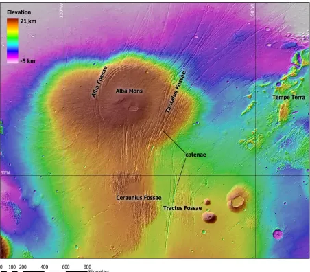
Figure 2 The Alba Mons volcano. ...4
Figure 3 A cartoon schematic of a graben in cross section. ...5
Figure 4 The relationship between vertical fault displacement (D) and fault length (L), shown here for an unrestricted normal fault. ...13
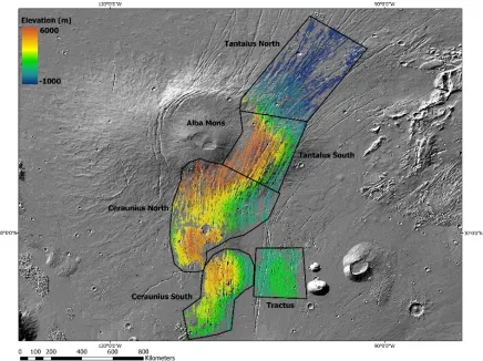
Figure 5 All faults mapped in this study, color-coded by mean elevation along strike. ...21
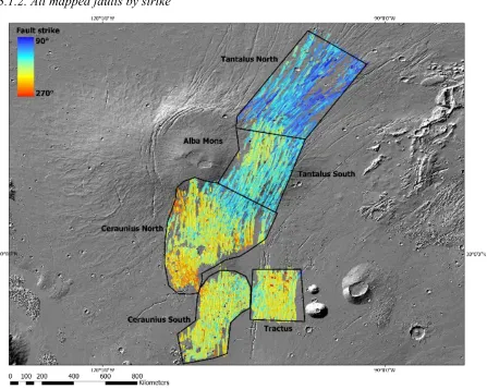
Figure 6 All faults mapped in this study, color-coded by along strike. ...22
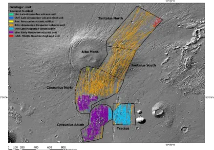
Figure 7 All faults mapped in this study, color-coded by geological unit. ...23
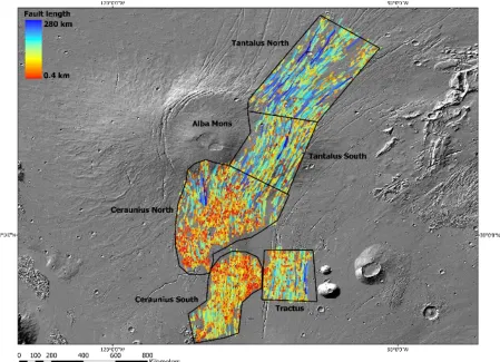
Figure 8 All faults mapped in this study, color-coded by length. ...25
Figure 9 All faults mapped in the “Tantalus North” study area, color-coded by strike. ....27
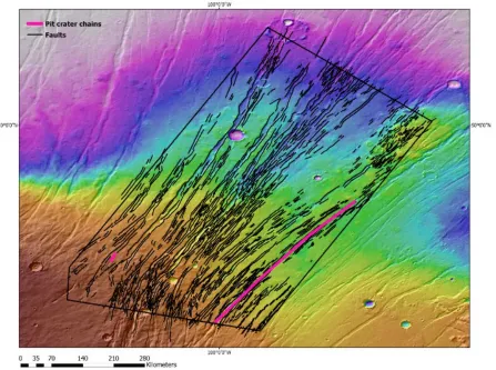
Figure 10 Trend of pit crater chains mapped with pits over 1 km in diameter mapped alongside all normal faults mapped in the “Tantalus North” study area. ...28
Figure 11 All faults mapped in the “Tantalus South” study area, color-coded by strike. ....29
Figure 12 Trend of pit crater chains with pits over 1 km in diameter mapped alongside all normal faults in the “Tantalus North” study area. ...30
Figure 13 All faults mapped in the “Ceraunius North” study area, color-coded by strike...31
Figure 14 Trend of pit crater chains with pits over 1 km in diameter mapped alongside all normal faults in the “Ceraunius North” study area. ...32
Figure 15 All mapped faults in “Ceraunius South” study area, color-coded by strike. ...33
Figure 16 Trend of pit crater chains with pits over 1 km in diameter mapped alongside all normal faults in the “Ceraunius North” study area. ...34
Figure 17 All mapped faults in “Tractus” study area, color-coded by strike. ...35
Figure 18 Trend of pit crater chains with pits over 1 km in diameter mapped alongside all normal faults in the “Tractus” study area. ...36
vii
Figure 20 Fault displacement profiles for all 14 study faults in “Tantalus North” ...39
Figure 21 Fault displacement profiles, normalized by length and maximum displacement, for all 14 study faults in the “Tantalus North” study area. ...40
Figure 22 Dmax/L ratios for this study plotted with corresponding measurements for structures on Earth ...43
Figure 23 The “Tantalus South” study area is shown with a grey outline, and the area for which crater statistics were obtained is outlined in black. ...45
Figure 24 The “Tantalus South” CraterStats surface age estimates ...46
Figure 25 The “Ceraunius South” study area is shown with a grey outline, and the area for which crater statistics were obtained outlined in black ...47
Figure 26 The “Ceraunius South” CraterStats surface age estimates ...48
Figure 27 Fault strike plotted by elevation for all mapped faults. ...50
Figure 28 Fault length plotted by distance from Alba Mons for all mapped faults. ...52
Figure 29 Fault strike plotted by distance from Alba Mons for all mapped faults. ...54
Figure 30 Fault strike plotted by latitude for all mapped faults. ...55
Figure 31 Faults that are (Left) only radial to Alba Mons and (Right) only circumferential to the volcano. ...56
Figure 32 Faults that are radial both to Alba and Tharsis ...57
1
1. Introduction, Background, and Overview
1.1. Geological Setting
Today, the planet Mars is in a phase of volcanic and tectonic quiescence (Cailleau et al., 2005). However, low erosion rates (Quantin et al., 2015) preserve billions-year-old volcanic and
2
The tectonic activity in the Tharsis region predominantly occurred in the early history of Mars, before 3.7 billion years ago (Ga), decreasing until the middle-late Amazonian epoch, 1.4–0.3 Ga (Anderson et al., 2001; Cailleau et al., 2005). However, the basic lithospheric structure and stress
3
fields of the Tharsis Region have likely not changed since early Martian history (~4 Ga)
(Anderson et al., 2001; Phillips et al., 2001; Williams et al., 2008; Golombek and Phillips, 2010). The entire region is characterized by a giant system of landforms interpreted as normal faults, formed by large-scale extensional stresses (Cailleau et al., 2005). The complexity of these faults renders Tharsis one of the most tectonically deformed and complicated regions on Mars.
4
The Alba Mons volcano itself (Figure 2), located at 20–60°N and 90–130°W (Ivanov and Head, 2006), is the largest edifice on Mars in terms of surface area. As a shield volcano, it is a broad, gently sloped (i.e., ~1°) construct (Plescia, 2004). The volcano and its environment are intensely deformed by faults (Raitala, 1988; Cailleau et al., 2005). Alba Mons has been a location of persistent volcanic activity during several 100-Myr time spans (Tanaka, 1990; Cailleau et al., 2003, 2005). Systems of normal faults cut across the volcano and the adjacent region, including circumferential faults that curve around the midflanks, and radial faults that extend from Tharsis highlands in the south to volcanic plains in the northeast (McGovern et al., 2001) (Figure 2).
5 1.2. Normal Faults and Graben
On the basis of image data returned for Mars (see Section 2.1), faults in the Alba Mons region are interpreted mainly as those with normal movement along the fault plane. Such faults form in an extensional tectonic regime, wherein the maximum compressive stress is oriented vertically, and the intermediate and minimum compressive stresses are horizontally oriented. If the yield strength of the crust is matched, shear failure along fault planes can occur (Figure 3). When two normal faults dip toward one another, such that the block of crust between them is
down-dropped, the topographic low is termed a graben. Such a scenario occurs because the initial normal fault that forms (the primary fault) flexes the adjacent crust until a new (secondary) fault forms that dips toward (i.e., is antithetic to) the primary fault (Melosh and Williams, 1989).
Figure 3. A cartoon schematic of a graben in cross section. Credit: ASU/Smithsonian Institution.
6
Matela, 1998) (Figure 2), the changes in graben orientation associated with the volcano, and the presence of distinct “patches” of graben at various distances to the volcanic edifice, it is clear that tectonic deformation in this region was far from straightforward.
Despite considerable focus on Alba Mons over the past several decades (see Section 1.3), several important questions remain. Did the graben in this region form solely from the stresses related to the Alba Mons volcano itself, are they part of a larger, Tharsis-related stress field, or might they even reflect the interaction between both local and regional stresses? Additionally, what was the nature of the faulting: a purely tectonic process, a process involving magmatism (such as dike intrusion), or, again, an interaction of both? These questions are much easier addressed for regions on Earth, where field studies and comprehensive geophysical measurements can test for the presence of tectonic versus volcanic activity, but for Mars we depend on observations returned by robotic spacecraft. Fortunately, substantial volumes of such data exist (see Section 2.1); moreover, that landforms are preserved on Mars for billions of years means that we are able to assess their morphology, and address these questions, long after tectonic activity has ended.
1.3. History of Mars Data
Viking 1 was the first spacecraft to provide global, high-resolution images of the surface of Mars. These images varied from 150–300 meters per pixel (m/px), and in some select areas of interest were at resolutions of up to 8 m/px. Several studies (e.g., Wise, 1976) and derived maps (e.g., Scott and Tanaka, 1986) used these images to investigate the pattern of faulting in the Tharsis region, including Alba Mons. In 1998, a global digital elevation model (DEM) became available thanks to the Mars Orbiter Laser Altimeter (MOLA) aboard the Mars Global Surveyor spacecraft (Smith et al., 2001). This new data set greatly facilitated the ability to study Martian tectonics. With the added third dimension (elevation), detailed structural studies could be
7
(MRO) Context Camera (CTX), are employed in this study of the tectonic characteristics and evolution of the Alba Mons volcano.
1.4. Previous Alba Mons Work
The first model to explain the complex fault pattern at Alba Mons was proposed by Wise (1976). In that study, Wise interpreted the faults of Alba and Tantalus Fossae (Figure 2) to be an
expression of lithospheric stresses produced by the crustal loading by the volcano itself. Indeed, he was the first to suggest that the fault patterns at the Alba Mons region resulted from a
combination of local, volcanic loading and a regional stress field. Numerical modeling by Wise (1976) reproduced circumferential faults by combining regional extension with a volcanic load on a thick plate, and predicted stresses to be generally E–W oriented, resulting in regional, Tharsis-originating faults with strikes that deviated from that trend in the vicinity of Alba Mons. This model, however, assumed that Alba Mons exerts only a surface load on the lithosphere, and so the results of Wise (1976) included only circumferential faults; the radial structures observed at the volcano were not replicated. Later studies (e.g., McGovern et al., 2001) determined that this incorporation of a surface load alone was the reason the model did not fully match
observations. Moreover, the Wise (1976) model also utilized very low regional stress values that were insufficient to reorient principal stresses to produce the observed fault pattern. This issue may have arisen because knowledge of the topography of the Alba Mons region was poor at the time of this work.
Although no radial structures were produced in the model reported by Wise (1976), subsequent studies (e.g., McGovern et al., 2001; Cailleau et al., 2005; Ivanov and Head, 2006) expanded on the concept of treating Alba Mons as a lithospheric load, with the general view that both regional and local stress fields were involved in graben formation in the vicinity of the volcano (Raitala, 1988; Turtle and Melosh, 1997). The ultimate goal of these subsequent studies was to
successfully account for both the circumferential and radial fault systems observed at Alba.
8
youngest: Noachian, Hesperian, and Amazonian. These systems were divided based on physical characteristics and stratigraphic relations observed with data returned by the Mariner-9 mission, a NASA orbiting probe that took photos of the surface from 1971 to 1972 (Hartmann and Raper, 1974). The later map (Scott and Tanaka, 1986) divided the Alba Mons region into three units: a Hesperian lower member (Hal), composed primarily of flood lava sheets (Cattermole, 1987); an Amazonian middle member (Aam) that surrounds the summit region; and an Amazonian upper member (Aau) that includes the summit region and is generally within the bounds of the circumferential graben (Schneeberger and Pieri, 1991). This mapping revealed two interesting observations: that Alba Mons’ topography is asymmetric with respect to the geologic units present there, and that the summit is offset to the south and west of the circumferential normal faulting at the volcano (McGovern et al., 2001).
The Scott and Tanaka (1986) map also documented temporal relations between units associated with Alba Mons and the surrounding fault systems, indicating for instance that the radial graben of Tantalus Fossae (Figure 2) are generally of the same orientation as Tempe Terra graben, which cut into Hesperian and Noachian units. Further, some Ceraunius graben continue into the Amazonian-era “At5” unit (interrupted as lava flows from the Tharsis Montes volcanoes). And the lower Alba unit is largely superposed by the Arcadia Formation in the north, yet some radial graben propagate into these units. This additional information helped to shed light on the relative timing of faulting at Alba Mons, the possible driving formation mechanisms, and the resultant control over fault orientations. Scott and Tanaka (1986) also reported observations of the individual structures themselves, attempting to tie their formation into the volcanotectonic history of Alba Mons. For instance, these workers concluded that resurfacing by lava flows likely contributed to the current distribution of faults on the flanks of the volcano. The upper geologic unit (“Aau”)—that is, the youngest flows of Alba Mons—shows evidence of fault reactivation and/or continued tectonic movements, due to some older faults being partially buried by flows that are in turn displaced by younger faults (Scott and Tanaka, 1980; 1986). This
9
Tanaka later narrowed his focus to a study on the tectonics of the Alba–Ceraunius region (Tanaka, 1990). With these observations, it became possible to construct a sequence of faulting in the area. Tanaka (1990) found that a first tectonic episode formed northeast-striking graben parallel to the Tharsis Montes (Figure 1), the Tantalus Fossae. A later and more widespread tectonic episode, probably related to Syria Planum- or Claritas Rise-centered radial faulting in the Noachian or in the early Hesperian (>3.6 Ga ago), formed the north-striking graben system, Ceraunius Fossae. The northern portion of Ceraunius Fossae that cuts across the main shield unit was reactivated—or was continuously active—until the early Amazonian (approximately 2.9–2.1 Ga). These Ceraunius Fossae structures imply an early E–W regional tensile stress field radial to Tharsis (Tanaka, 1990).
In a study of Tharsis rise-related structures, Tanaka et al. (1991) concluded that linear graben in the vicinity of Alba Mons (Fig. 2) could be generally attributed to regional extension arising from activity centered at Tharsis itself. These workers suggested that radial-to-arcuate graben on the flanks of Alba Mons may have been induced by spreading of the volcano (e.g., Borgia et al., 2000) enabled by a ductile layer between the upper crust and the strong upper mantle (Tanaka et al., 1991).
10
Turtle and Melosh (1997) regarded Alba Mons’ circumferential faults as a manifestation of volcanic surface-load stresses. These authors built on the model proposed by Wise (1976) by starting with a surface load emplaced on an elastic plate overlying an inviscid substrate. Turtle and Melosh (1997) varied in their numerical model load dimensions and elastic lithosphere thickness to fit the then-available topography and gravity data, and calculated a thickness of the lithosphere of 10–50 km. To match the observed fault trends, these workers superposed a regional stress field onto the volcano-driven flexural stress. They found that extensional stresses with magnitudes of 150–200 MPa, combined with the local axisymmetric stress field arising from the loading of the lithosphere by Alba Mons, could create the observed pattern of strain. However, such a stress magnitude is beyond the highest recorded strength of intact basalt (tensile strength, −14 MPa), and so the prospect for stresses this high acting on the Martian lithosphere is unlikely (Schultz, 1993).
The acquisition in the early 2000s of the MOLA global topographic dataset by the Mars Global Survey mission (Smith et al., 2001) revealed a key observation: that Alba Mons is a much larger volcano than previously assumed. In Viking images, it appeared that the volcano was almost entirely situated between Alba Fossae, to the west, and Tantalus Fossae, to the east (Mouginis-Mark et al., 1988; Cattermole, 1990; Turtle and Melosh, 1997) (Figure 2). However, MOLA indicated that the shield actually extends from 20–60°N and 90–130°W (Ivanov and Head, 2006). With these new elevation data, workers were able to study the graben of Alba Mons region in much greater detail. For example, it became apparent that the circumferential graben of Alba Fossae are at higher elevations, on average, than those of Tantalus Fossae: indeed, the western quadrant of Alba Mons lies more than 1 km higher on the midflank than its eastern counterpart (McGovern et al., 2001). Additionally, it became clear that the circumferential faults cut into the midflank of the volcano, casting doubt on the view that they were caused purely by surface loading (e.g., Wise, 1976; Turtle and Melosh, 1997) of the volcanic edifice (McGovern et al., 2001).
11
uplift from a deep, buoyant sublithospheric load (e.g., underplated magma), focusing more on intralithospheric loading (e.g., magmatic intrusions such as dikes and sills, or underplating) than the previous surface load models (Wise, 1976; Turtle and Melosh, 1997). With this approach, McGovern et al. (2001) explained the lower-flank faults that transition from circumferential to radial as conjugate shear planes, such that these faults may have both dip-slip and strike-slip displacements. These workers proposed that such oblique-slip displacement could allow dikes to preferentially follow these linear fractures and influence radial graben orientation.
A subsequent finite element model (FEM) study (Cailleau et al., 2003) noted that faults
circumferential to Alba Mons formed after the radial graben, suggesting a temporal change from a radially to a circumferentially oriented extensional stress field. The model of Cailleau and co-authors supported the view that local subsidence, paired with regional extension, drove the formation of the extensional, circumferential faults on the volcano. These authors next studied the radial faults with an updated FEM (Cailleau et al., 2005) and argued that, based on
observations of converging fault patterns, the radial structures of Tantalus Fossae resulted from local, Alba Mons-related stresses at a time of widespread volcanism. This later study (Cailleau et al., 2005) focused on fine-tuning the model of McGovern et al., (2001), which could not
12
Cailleau et al. (2005) did not address the striking difference in number and spacing of graben on either side of the Alba Mons summit (Ivanov and Head, 2006).
Ivanov and Head (2006) agreed that the normal faults on Alba Mons’ flanks are, in general, the youngest features of the volcano (and placed them in early Amazonian), and that these structures postdate the formation of the central edifice. These authors reconsidered the early hypothesis that the majority of Alba Fossae formed as a response to the loading of the summit dome and
solidification of the magma reservoir (Wise, 1976; Walker, 1984, 1988). Tantalus Fossae, Ivanov and Head (2006) argued, may instead represent the long-lived and presumably deep-seated main tectonic zone (resulting from a Tharsis-related, regional stress field) that existed before the formation of Alba Mons, and that was reactivated because of Alba’s volcanic loading.
Displacement along circumferential Tantalus Fossae faults accommodated tilting of the eastern flank lobe of Alba Mons, and this deformation could be responsible the asymmetry of both the volcano’s topographic form and the distribution of volcanic units on and around the shield (Tanaka, 1986). In their study, Ivanov and Head (2006) employed then-newly available Thermal Emission Imaging Spectrometer (THEMIS) infrared image data (with a resolution of 100 m/px) to assess in relatively high resolution both individual structures and the cross-cutting relations between graben and lava flows.
Following THEMIS, orbiting cameras imaged the surface of Mars at increasingly higher resolution (see Section 2.1). With these new data, especially when combined with topography from, for instance, the MOLA DEM, it became possible to investigate smaller faults and thus more complex cross-cutting patterns, explore relative age relations in more detail, characterize fault morphology more fully, and search for evidence of erosion. It is with this wealth of high-resolution images and data that structural geologists began to study the Alba Mons region graben to a greater extent than before, focusing on individual faults’ geometric properties and age-relations within fault systems, further refining theories of formation for these structures.
13
factors leading to Martian fault growth and fault population evolution (e.g., Schultz, 1991, 1997; Polit et al., 2009). In the case of Alba Mons graben, this method involves measuring for
individual graben-bounding normal faults the total fault length (L) and the maximum vertical displacement (Dmax), which requires horizontal and vertical measurements (and, therefore, high-resolution topographic data). Studies of fault populations on Earth have found that the
relationship between maximum displacement and total fault length is, generally, linear in nature (Dawers et al., 1993). Nonetheless, it has been shown that this scaling ratio is lower by
sometimes as much as a factor of five for Martian and Mercurian faults, possibly because of the lower surface gravitational accelerations on those worlds compared with that of Earth (Schultz et al., 2006).
Figure 4. The relationship between vertical fault displacement (D) and fault length (L), shown here for an unrestricited normal fault. Ideally, maximum vertical displacement (Dmax) is situated at the center of the fault and D goes to zero at the tips. Figure from Fossen (2010).
14
implications for Dmax/L scaling because ratios for the faults that are mechanically restricted do not scale linearly, in contrast to the generally linear scaling ratio of unrestricted faults (e.g., Dawers et al., 1993). Additionally, Polit et al. (2009) concluded that the faults closer to Alba Mons possess greater extensional strain, and are therefore more likely to be the result of local stresses centered in the Alba Mons vicinity, than those farther from the shield, to which these workers attributed an origin from regional stresses arising at the Tharsis center.
It is important to note that, although many studies and models over the years converged upon a dike-related origin for graben in the Tharsis region (e.g., Mège and Masson, 1996; Ernst et al., 2001; Cailleau et al., 2005), Polit et al. (2009) found no evidence for any volcanic activity that might have been associated with such dikes, were they present (e.g., pit craters, troughs, or emanating lava flows) in either of the two areas these authors studied (the graben on the flanks of Alba Mons and those that extend into the northern plains). Finally, Wyrick et al. (2011)
conducted a structural study of circumferential and radial Alba Fossae faults on the northwest flanks of Alba Mons where they measured maximum fault displacements and lengths, thus calculating Dmax/L ratios, for over 300 normal faults. In the Wyrick et al. (2011) study area, substantial fault lengths tend to reflect fault linkage, which is the primary determinant of fault length, and results in lower Dmax/L values.
1.5. Study Rationale
Firstly, I believe that to properly investigate the origin of stresses that caused the Alba Mons region graben, and more importantly, the possibility of these structures reflecting more than a single stress field, the graben systems around the volcano (i.e., Tantalus, Alba, and Ceraunius Fossae) need to be split into smaller study areas than have been assessed so far. By doing so, especially with recent high-resolution image data, it will be possible to test existing hypotheses for the formation and timing of the complex extensional systems of structures around the
15
To test this hypothesis, my approach is to split these faults into five discrete “study areas,” with that division based primarily on fault orientation and distance to the volcano, and then selecting a further subset of faults in each area for detailed structural analysis. The basis by which I select these study fault subsets is described in Section 4.4. After acquiring detailed measurements of fault properties, I will assess the spatial variation of those properties with distance from Alba Mons as well as distance from Tharsis, with a view to attributing the faults to the volcano, to Tharsis, or to both. I will also focus on the temporal component of tectonic deformation, especially on fault cross-cutting relations and on the absolute model ages of two areas in particular, assessed with crater statistics.
2. Methods
2.1. Data
The primary base maps used for digitizing faults and related landforms for this study include the “Day IR” global mosaic from the Thermal Emission Imaging System (THEMIS) instrument. This instrument arrived in Mars orbit in 2001 aboard the NASA Mars Odyssey orbiter, and acquires image data of the surface in both the visible and infrared, both during the Martian day and at night. Like a conventional imaging system, data from the THEMIS instrument reveal details of the Martian surface and the morphology of the landforms there. The THEMIS Day IR mosaic is particularly useful because it has global coverage of the planet’s surface at a resolution of 100 m/px.
16
study region that HRSC does not, and so these data together provide an enhanced view of the study region over THEMIS alone.
To assign inferred lithologies and stratigraphic ages to faults in this study, the most recent global geological map was used. This updated map by Tanaka et al. (2014) reports adjusted absolute ages for several units, including those within the study region. (For example, geological units associated with Ceraunius Fossae are updated from Noachian-age to early and late Hesperian.
2.2. Study Areas
Previous analyses of the extensional systems associated with Alba Mons considered the graben sets as a group. It is my view, however, that the complexity of faulting in the Alba Mons region necessitates the partioning of these fault systems into smaller study areas. This opinion is based on the presence in some places of at least four different and resolvable fault strike orientations, the general complexity of cross-cutting relationships of faults in the region, the possibility of fault reactivation, and the prospect that some areas experienced both regional- and local-scale stresses (and possibly both simultaneously) at different times. For these fault systems to be compared and contrasted properly, and to attempt to craft a synthesis of deformation history as recorded by these fault populations, dividing this large study region into smaller areas is necessary.
17
major structural complexity, with up to four distinct strike orientations. For the purpose of this study, then, I divided both Tantalus and Ceraunius into “north” and “south” areas. The fifth study area, “Tractus”, is comparatively distant from the volcano (~900 km from the caldera complex), but is included in this project because of its structural similarity to the other faulted areas. Additionally, it is necessary to compare faults near the volcano with those that are farther away, to test the extent to which local- versus regional-scale stresses have acted upon this part of Mars.
Study Area Centered at Geologic unit(s) Fault strike
Tantalus North 99° W, 48° N ■ Amazonian-Hesperian volcanic unit (AHv)
■ Middle Noachian highland unit (mNh) NE
Tantalus South 102° W, 39° N ■ Ahv N to NE
Ceraunius North 108° W, 33° N ■ Late Amazonian volcanic unit (lAv) ■ Late Amazonian volcanic field unit (lAvf) ■ Amazonian volcanic edifice (Ave)
■ AHv
■ Early Hesperian volcanic unit (eHv)
N
Ceraunius South 108° W, 23° N ■ lAvf
■ AHv
■ Late Hesperian volcanic unit (lHv) ■ eHv
N
Tractus 101° W, 26° N ■ lAv
■ AHv ■ lHv
N
2.3 Mapping Methods and Techniques
Mapping was performed with ESRI’s ArcGIS ArcMap v. 10.6, using as a base map the THEMIS Day IR global image mosaic, together with a global hillshade derived from MOLA topography, and supplemented with high-resolution images as needed and where available. Landforms were mapped at a scale of 1:200,000 and saved in separate ArcGIS shapefiles for each study area.
Mapped structures include fault scarps, pit crater chains, sinuous channels, and impact craters. Fault scarps were mapped as linear features, identified as such with the THEMIS base map with help of the MOLA DEM. Inferred fault down-dip direction was recorded with a hatched line symbology. Fault strike was calculated with the EasyCalculate10 Add-In for ArcMap, which finds the azimuth of the bearing of the fault scarp polyline; this value was then converted into strike (and given as a three-digit number between 0° (000) and 180° (180)). In addition to fault
18
scarps, pit crater chains were mapped by recording an approximate strike of the chains of craters separately, for use in comparison of fault and pit crater chain orientations. Several examples of sinuous channels of indeterminate origin are present in the study region, and so were also digitized as linear features with polylines that follow their curved morphology. Impact craters of all sizes at mapping scale were mapped as circular features, for use in crater statistics studies.
The geodetic distance of a given structure to Alba Mons was measured with the Euclidean distance tool in ArcMap. The latitude of each fault is used as a proxy for its distance from the Tharsis region, because that major volcanotectonic rise is centered approximately at the equator. To represent the centers of individual faults, the centroids of their shapefile polylines were calculated.
2.4. Analyses for All Mapped Faults
All normal faults in the study region were identified with the image and topographic data described above. For each of these structures, key geometric and geological properties were recorded including fault length, strike, elevation, geological unit in which they occur, their distance from Alba Mons, distance from Tharsis, and any cross-cutting relationships with adjacent faults with different strikes.
Most graben have one bounding fault, often referred to as the “primary” fault that has more vertical displacement than the other. Where a difference in vertical relief (and thus inferred fault throw) was identified for the bounding faults of a given graben, the larger fault was interpreted as the primary fault and its location and down-dip direction recorded. Primary and secondary faults are predicted to form together (Illies, 1981), and so the location and dip direction of the primary fault may indicate the source of the stress field which activated faulting. Additionally, in rift-type extensional provinces, transfer faults will switch primary faults from one graben
segment to another (Mège and Masson, 1996; Ernst et al., 2001), and so evidence for such switching was also noted.
19
resolution image data available, and locations of cross-cutting and stratigraphic relationships were investigated to determine the relative ages of mapped faults. This is important because many areas, especially “Ceraunius North,” “Ceraunius South”, and “Tantalus South,” have at least three distinct fault orientations (see Section 3.1.2) that plausibly indicate multiple phases of faulting and/or changes in stress orientation(s).
2.5. Fault Analysis
Several faults (graben-bounding pairs) in each study area were selected for detailed structural analysis. These study fault subsets were selected on the basis of their suitability for
three-dimensional geometric investigations at the resolution of the MOLA topographic data, which has substantially lower horizontal resolution (463m/px) than the THEMIS global image base map (i.e., 100m/px). When selecting the subset of study faults from the entire fault population of this region, consideration was given to the importance that selected faults be a good representation of structural trends for their respective study areas. As a result, and to the maximum extent possible, the data set of study faults included faults of as broad a range of orientations, depths, and spatial extents as possible. For the derivation of a ratio relating fault length to displacement, it is also preferable that study faults be as isolated as possible, i.e., they must have had minimum mechanical linking with adjacent faults, and must also have minimal modification by cross-cutting, impact cratering, infill by lavas, and mass-wasting. Satisfying these latter criteria for faults in the study area was challenging, however, due to the high level of structural complexity of the graben systems here, especially in the “Ceraunius South” study area. I measured fault length and graben width from the base map of THEMIS images and MOLA elevation, and I measured the vertical relief of a given fault scarp as recorded with the MOLA cross-sections. Only hard-linked (i.e., physically linked at the surface) faults are considered to be continuous.
20
each fault, then, the maximum vertical displacement value was taken as the greatest relief value from the profiles along a given fault. A ratio of maximum vertical displacement (Dmax) to total fault length (L) was then calculated for each study fault. (This ratio is the displacement–length ratio (Dmax/L) of the fault.)
2.6. Crater Statistics Analysis
Absolute model ages were calculated for two study areas, “Tantalus South” and “Ceraunius South.” These areas were chosen because they are proximal and distal to the volcano, respectively, and because sufficient CTX and HRSC image coverage is available. By
determining model ages for these surfaces with all craters present, I can test the stratigraphic interpretations for the units in these areas by Tanaka et al. (2014). Moreover, by calculating model ages with only those craters in each of these areas that are not faulted, we can place an estimate on the timing and even duration of extensional deformation in “Tantalus South” and “Ceraunius South.” To map the primary impact craters at each site, I used the CraterTools extension (Kneissl et al., 2011) for ArcMap 10. Absolute model ages were determined for each site with the “Craterstats program” (e.g., Michael and Neukum, 2010), using the model
production function and chronology of Ivanov et al. (2001). The CraterStats model ages are calculated by Poisson timing analysis (Michael et al., 2016), given assumed scaling relations between impactor diameter and crater diameter. The determination of model ages with Poisson timing analysis returns plots of model age uncertainty as a probability density function, marked by vertical lines at the 50 ± 34 percentiles (Michael et al., 2016). Because systematic
uncertainties in the chronology model are much larger than errors from counting statistics (by at least several hundred million years) and are not very well constrained, I give model ages in Section 3.5 only to two significant figures.
3. Results
21
Next, qualitative descriptions of the five study areas are given, including general fault strike and observations of any abrupt changes or cross-cutting patterns that occur, comparisons between normal fault strike and orientations of other linear features (i.e., pit crater chains), and other relevant morphological observations of landforms in the study area. Then, the results for in-depth structural analyses of a select subset of normal faults in each of the five study areas are reported, followed by the crater statistics results.
3.1. Study Region Results
3.1.1. All mapped faults by elevation
Figure 5. All faults mapped in this study, color-coded by mean elevation along strike.
22
they are situated on a broad volcanic edifice, but there are also areas in the “Ceraunius North” and “Ceraunius South” study areas south of the volcano that are situated at elevations of between 3 and 6 kilometers.
The lowest elevation faults are in the “Tantalus North” study area to the northeast of the volcano, and are situated below 0 m elevation (i.e., the Martian “sea level”, given as that elevation where the gravitational potential of the planet is equal to the mean radius (Smith et al., 2001)).
3.1.2. All mapped faults by strike
Figure 6 shows all mapped faults in the study region color-coded by strike (that is, the bearing relative to 0° of the normal fault scarp). The specific strike value for each structure corresponds to the angle of a line that extends from the start and end point of the digitized fault trace. It is clear both that fault strike is generally consistent in each study area, and a generally continuous
23
northeasterly change in strike at progressive latitudes, but there are also instances of abrupt changes in strike and patches of cross-cutting faults in places.
Figure 7. All faults mapped in this study, color-coded by geological unit (from Tanaka et al., 2014).
Study Area # Faults Mean Strike (°) Strike S. D. (±°)
Tantalus North 1,054 039 16
Tantalus South 1,320 022 14
Ceraunius North 3,676 003 19
Ceraunius South 3,728 004 16
Tractus 1,518 004 16
Study Total: 11,296 Study Mean: 015
24
The geospatial distribution of fault strike for each of the five study areas is given in Table 2. It is clear from this tabulation that, in order of descending latitude, fault strike is notably different in the northern study areas (i.e., “Tantalus North” and “Tantalus South”), compared with the three study areas that are south of Alba Mons (“Ceraunius North,” “Ceraunius South,” and “Tractus”). The geological unit classifications published by Tanaka et al. (2014) were added to the fault database, to analyze patterns of fault strike in regard to interpreted bedrock geology and relative stratigraphic age. From a comparison, then, of fault trace mapping and geological unit (Figure 7), it appears that bedrock geology cannot be relied upon to determine the origin of faults in the study region.
Geological Unit (youngest to oldest) # Faults Mean # Strike (°) Strike S. D. (±°)
■ Late Amazonian volcanic unit (lAv) 51 005 20
■Late Amazonian volcanic field unit (lAvf) 64 167 15
■ Amazonian volcanic edifice (Ave) 58 016 17
■Amazonian-Hesperian volcanic unit (AHv) 5,312 018 22
■ Late Hesperian volcanic unit (lHv) 1,752 005 17
■ Early Hesperian volcanic unit (eHv) 4,571 002 17
■ Middle Noachian highland unit (mNh) 92 048 10
Total/mean Study total: 11,900 Study mean: 011
Table 3 lists the total faults in each geological unit (i.e., those from the geological map of Tanaka et al. (2014)), as well as the mean fault strike for each of the geological units that comprise the study region. The only conclusion that can be made from this data is that bedrock geology is not controlling the strike of these faults (based on the high standard deviation for fault strike mean in Table 3), and the fact that every geologic unit in this region is host to faults with a wide range of strike (and, in the case of study areas “Ceraunius North” and “Ceraunius South,” a lot of cross-cutting). However, it is worth noting that the two southernmost study areas (“Ceraunius South” and “Tractus”) are almost entirely comprised of Hesperian (3.7–3.0 Ga) geologic units with thousands of mapped faults that strike nearly due north (Table 3).
25 3.1.4. All mapped faults by total fault length
Figure 8. All faults mapped in this study, color-coded by length.
26 3.2. Study Area Results
3.2.1. “Tantalus North”
27
28
Faults in this study area generally trend northeast, with a mean strike of 039° (see Table 2). At 42–45° N, there is an combination of two fault arrays, defined on the basis of strike, that cross-cut one another, with some faults slightly curving around the volcano (i.e., the warm colors at the southern margin in Figure 10). The bulk of faults in this study area form graben that are
hundreds of meters deep and several kilometers wide, trend northeast, and appear to be older in age than faults that strike more north-south, based on cross-cutting relationships (Figure 9, dark blue colors). At 45–54° N, all faults trend northeast, are mainly parallel to one another, and thus rarely intersect. At 50–54° N, faults begin to fan out toward north and northeast, with strikes ranging from 011° to 074° (Figure 9). Within this study area, there is one 416 long, ~1.6
29
deep pit crater chain (named Phlegethon Catena) that trends approximately 049° (Figure 10). Faults adjacent to this pit crater chain (within ~80 km) strike parallel to its general trend (049°).
3.2.2. “Tantalus South”
This study area is primarily located on the eastern flanks of Alba Mons, and all faults here cut into the “Amazonian-Hesperian volcanic” (Ahv) geological unit. There are 1,320 faults
mapped in this area (Figure 11). As for “Tantalus North,” this study area also includes two very long pit crater chains, Phlegethon and Archeron Catenae (the former of which extends into the more northerly area).
Approximately 75% of mapped faults strike northeast (between 015° and 060°), with a mean strike for the entire study area of 023° (Figure 11, light blue–green colors). However, some
30
cross-cutting occurs in the center–north of the area (Figure 11, yellow–orange colors), with the other 25% mapped faults that strike more northerly to northwesterly (between 135° and 015°) (Figure 11, yellow–orange colors).
The array of faults (25% of the study area total) that strikes north–northwest is entirely located within ~450 km radius of the volcano’s caldera complex. These faults and fault segments have linked in a stepwise fashion that makes longer graben appear to slightly curve (~0.1 degree/km) around the flanks (Figure 11, yellow colors). Pit crater chains (Phlegethon and Archeron Catenae), both of which trend 035° in this study area (Figure 12), are slightly oblique to the
31
mapped faults. The northeast-trending faults appear older, but they are in turn are cut by younger (or more recently active) pit crater chains.
3.2.3. “Ceraunius North”
Figure 13. All faults mapped in the “Ceraunius North” study area, color-coded by strike. Strikes here are complex. The mean strike is N–S (003°); however, there are several areas with
incongruent patches of faults (red and blue colors) that have been cut by these N–S-striking faults.
32
Figure 14. Trend of pit crater chains with pits over 1 km in diameter (hot pink) mapped alongside all normal faults (black) in the “Ceraunius North” study area. The base map is color-coded MOLA elevation atop a MOLA-derived hillshade.
There are a total of 3,676 faults mapped in this area, and 83 pit crater chains with individual pits over 1 km in diameter.
33
and when compared with mean fault strike in the study area (003°), are oblique to these faults. Of note, however, normal faults adjacent (within 200 km radius) to these catenae are parallel with them. Smaller-scale (3–100 km long) pit crater chains that contain at least one pit crater over 1 km in diameter in this study area (n = 83) trend at a mean 015°, ranging from 153° to 072°.
3.2.4. “Ceraunius South”
Faults in the “Ceraunius South” study area generally trend north–south, with a mean strike of 004° (Table 2), but there is considerable cross-cutting of faults of different strikes. Most mapped faults in this study area (~90%) deform the “early Hesperian volcanic unit” (eHv). There are 3,728 faults mapped in this region, and 42 pit crater chains.
34
This area has substantial cross-cutting of faults in the northeast (Figure 15, blue colors). Some of the faults that strike northeast are in fact on the horsts of larger, adjacent graben.
The long, deep regional catanae here strike 070° (Figure 16). There are also 42 pit crater chains (2–56 km long), of which most are parallel with the surrounding faults (from 154–015°), but some are perpendicular to the mean fault strike (up to 090°) (Figure 16).
35
Figure 17. All mapped faults in “Tractus” study area, color-coded by strike. 3.2.5. “Tractus”
36
Figure 18. Trend of pit crater chains with pits over 1 km in diameter (hot pink) mapped alongside all normal faults (black) in the “Tractus” study area. The base map is color-coded MOLA elevation atop a MOLA-derived hillshade.
37 3.3. Study Fault Results by Study Area
Here, I present the results for select subsets of normal faults in each of the five study areas. The 62 study faults are in 31 pairs because they represent the two bounding faults (primary and secondary) of a graben. These faults were selected based on their isolation from other faults (which nominally reduces the prospect for fault linkage), craters, mass wasting deposits, and other landforms that might impede a structural study.
The following results include ranges and mean measurements for fault strike, total fault length, maximum graben width (i.e., the horizontal distance between the pairs of fault scarps), maximum
38
vertical relief (i.e., the inferred vertical fault displacement), and the dip direction of the primary fault. These results also include the Dmax/L ratio and displacement profile for each study fault.
3.3.1. “Tantalus North” study fault results
Fourteen faults (seven pairs of graben-bounding faults) in this study area were selected for more in-depth structural analysis. Results for this study area are presented in Table 4. For individual measurements, see the Appendix. Study faults in “Tantalus North” have the highest mean lengths and widths of the five study areas. Due to the long fault lengths (44–131 km), this area has the lowest measured Dmax/L ratio values (2.0 × 10⁻³) in the study region.
Fault Property Value Range Value Mean
Strike 027–057° 040°
Total length 44–131 km 95 km
Maximum graben width 4.6–9.4 km 6.9 km
Vertical relief (displacement) 85–391 m 200 m
Primary fault dip direction n/a Mixed
Dmax/L 1–4.5 × 10⁻³ 2.20 × 10⁻³
39
Fault displacement profiles for the study area show both peaked and plateaued profile shapes (Figure 20). For example, fault pair “AE3E” and “AE3W” shows the characteristics peaked profile shape. In contrast, fault pair “AE9E” and “AE9W” shows a plateaued displacement profile: displacement for this pair maximizes at ~125 m at a distance of around 20 km along the length, and remains largely constant across the structure until ~80% of the length. Of the 14 faults measured, six are peaked and eight are plateaued (Figure 20). Note that the profiles shown in Figure 20 are given without scaling, i.e., they are shown with their true dimension. These same profiles are shown in Figure 21 normalized by length and maximum displacement.
40 3.3.2. “Tantalus South” study fault results
Ten faults (five pairs of graben-bounding faults) in this study area were selected for more in-depth structural analysis. Results for this study area are presented in Table 5. For individual measurements, see the Appendix.
Fault Property Value Range Value Mean
Strike 016–033° 024°
Total length 33–99 km 68 km
Maximum graben width 3.6–12.8 km 6.8 km
Vertical relief (displacement) 19–449 m 189 m
Primary fault dip direction n/a West
Dmax/L 0.6 × 10⁻³–4.7 × 10⁻³ 2.6 × 10⁻³
Figure 21. Fault displacement profiles, normalized by length and maximum displacement, for all 14 study faults in the “Tantalus North” study area.
41
Study faults in “Tantalus South” have the second highest mean lengths (68 km) and widths (6.8 km) of the five study areas. Due to the long fault lengths (33–99 km), this area has the second lowest measured Dmax/L ratio values (3.0 × 10⁻³) in the study region. Fault displacement profiles for the study area show that eight of the ten profiles are peaked, with the remaining two being plateaued.
3.3.3. “Ceraunius North” study fault results
Fourteen faults (seven pairs of graben-bounding faults) in this study area were selected for more in-depth structural analysis. Results for this study area are presented in Table 6. For individual measurements, see the Appendix.
Fault Property Value Range Value Mean
Strike 339–027° 000°
Total length 34–97 km 58 km
Maximum graben width 3.3–11.5 km 6.0 km
Vertical relief (displacement) 67–398 m 222 m
Primary fault dip direction n/a Mixed
Dmax/L 1.0 × 10⁻³–6.8 × 10⁻³ 4.0 × 10⁻³
Study faults in “Ceraunius North” have the second lowest mean lengths (58 km) and the second-highest values for maximum vertical displacement (222 m). Due to the short fault lengths (34–97 km) and high vertical displacement, this area has the highest measured Dmax/L ratio values (4.0 × 10⁻³) in the study region. Fault displacement profiles for the study area show that eleven of the fourteen profiles are peaked, with the remaining three being plateaued.
3.3.4. “Ceraunius South” study fault results
Ten faults (five pairs of graben-bounding faults) in this study area were selected for more in-depth structural analysis. Results for this study area are presented in Table 7. For individual measurements, see the Appendix.
42
Fault Property Value Range Value Mean
Strike 357–032° 008°
Total length 18–108 km 64 km
Maximum graben width 1.9–5.2 km 3.8 km
Vertical relief (displacement) 70–655 m 229 m
Primary fault dip direction n/a Mixed
Dmax/L 1.1 × 10⁻³–7.4 × 10⁻³ 3.7 × 10⁻³
Study faults in “Ceraunius South” have the second lowest mean graben widths (3.8 km) and the highest values for maximum vertical displacement (229 m). This area has the second-highest measured Dmax/L ratio values (3.7 × 10⁻³) in the study region. This finding may reflect the comparatively short fault lengths (the mean of which is 64 km) but relatively high vertical relief (and, thus, interpreted vertical displacement components on the faults) of these structures (i.e., a mean of 229 m, 22% greater than the mean vertical relief for all 62 study faults: see Appendix). Fault displacement profiles for the study area show that all ten profiles are peaked.
3.3.5. “Tractus” study fault results
Fourteen faults (seven pairs of graben-bounding faults) in this study area were selected for more in-depth structural analysis. Results for this study area are presented in Table 8. For individual measurements, see the Appendix.
Fault Property Value Range Value Mean
Strike 347–018° 007°
Total length 10–98 km 43 km
Maximum graben width 2.1–4.9 km 3.0 km
Vertical relief (displacement) 37–279 m 101 m
Primary fault dip direction n/a East
Dmax/L 0.7 × 10⁻³–6.7 × 10⁻³ 3.1 × 10⁻³
Study faults in “Tractus” have the lowest mean graben widths (3.0 km) as well as the lowest mean value for maximum vertical displacement (101 m). Due to the low vertical displacement, this area has the second-lowest measured Dmax/L ratio values (3.1 × 10⁻³) in the study region. Fault displacement profiles for the study area show that all fourteen profiles are peaked.
Table 8. Results for selected faults in the “Tractus” study area (n = 14).
43
However, seven of these faults are “peaked asymmetric left”; that is, the maximum displacement is not situated at the center of the fault’s length, but is instead skewed toward their respective northern tip. (As stated above, these profiles are given in the Appendix.)
3.4. Study Fault Results Collectively
In Figure 22, fault Dmax/L ratios from this study are plotted alongside data from previous studies. Data from this study are shown as hot pink dots. They plot slightly lower than data
for faults on Earth. My data, however, plot on top of another Mars normal fault study (data provided by C. L. Kling, personal communication, November 2018).
Figure 22. Dmax/L ratios for this study (points in hot pink) plotted with corresponding
44 3.4.1. Dmax/L ratios
Study Fault Study Area Strain (%)
AE9 Tantalus North 1.7
TA2 Tantalus South 2.0
CN2 Ceraunius North 5.3
CS1 Ceraunius South 2.6
TR1 Tractus 3.0
3.4.2. Extensional strain
I measured the amount of horizontal extension recorded by five fault-bound graben in the study region (one per study are). Extensional deformation was measured as longitudinal strain, whereby the horizontal distance between bounding fault scarps was measured, followed by a measure of the horizontal component of fault displacement (heave), i.e., the geometric horizontal dimension of the graben walls when viewed from above. Taking the difference in these length values as a percentage of the total distance between fault scarps, an estimate of horizontal extensional strain was calculated for each graben. These measurements are given in Table 9.
3.5. Crater Statistics Results
With a view to determining how much time elapsed since the most recent incidents of faulting proximal to Alba Mons, impact craters over 2 kilometers in diameter were mapped from CTX and HRSC imagery for two sites. Craters below this diameter threshold may be secondary craters, the inclusion of which in my counts would provide an erroneously old surface model age. Obvious secondary craters were excluded on the basis of their occurrence in clusters or chains, but far-field secondaries cannot be readily recognized, and the contamination of counts by unrecognized secondaries is expected to become increasingly severe at smaller crater
diameters. All craters in each of the two study sites were mapped as circles in a single polygon. A subset of these craters is visibly faulted, and those craters were recorded in a separate
shapefile.
45
As described in Section 2.6, all mapping was carried out with the CraterTools plug-in for ArcMap. Once the craters were recorded, they were analyzed with the CraterStats program (Michael et al., 2013). First, a model age for the surface from all mapped craters was calculated, followed by an age given only by those craters that show no evidence of being offset by fault motion, which corresponds to the time elapsed since the end of deformation (Section 2.6). This approach was followed for both study areas, and the results are described below.
3.5.1. “Tantalus South” crater statistics results
46
A total of 10 craters with diameters over 2 km were identified and mapped in “Tantalus South”, in the areas where HRSC imagery was available (Figure 23, black outline). This moderate-resolution imagery (~10 m/px) revealed craters that have been deformed by normal faults, i.e., their rims and/or floors have been deformed by normal faults and thus were in place before at least the last instance of strain. Two of the 10 craters in this study area were found to be faulted, and eight were found to be intact.
Of note, estimates for both total surface age and elapsed time since deformation both have substantial margins of error, likely due to the small number of impact craters in the areas for which crater statistics were obtained. This is a limitation of the technique. Nonetheless, taking the calculated Poisson ages for each site (Michael et al., 2016) the total the surface area
examined here is 2.2 Gyr and the last deformation (faulting) occurred at 1.9 Ga. Per these model ages, there was a ~300 Myr period during which faulting occurred.
3.5.2. “Ceraunius South” crater statistics results
A total of 21 craters with diameters over 2 km were located and mapped in “Tantalus South”, in the areas where HRSC imagery was available (Figure 24, black outline). This
moderate-resolution imagery revealed craters that have been deformed by normal faults since impact. Ten of the 21 craters in this study area were identified as faulted, and eleven were found to be intact.
47
As for the “Tantalus South” study area, the absolute model ages for the total surface age and the time since deformation for “Ceraunius South” both have substantial margins, again probably because of the limitation of small-number statistics. However, on the basis of these estimated ages, the surface area is 3.4 Ga and the last deformation (faulting) occurred at 2.5 Ga. This means that there was a ~900 Ma time period when faulting occurred.
48
4. Discussion
In this section, I interpret my mapping and structural analyses results, and discuss the
significance of differences in fault properties across the study region—first for all faults mapped, and then for the subset of study faults. The results and implications of the crater statistics
analysis are then discussed. I also attempt to ascribe fault populations to either regional or local stress fields, against which I compare the findings of previous studies.
4.1. All Faults
Here, I discuss the results for all faults mapped and measured in the entire study region (n = 11,767), including properties such as fault elevation, length, strike, and geological unit in which it occurs. These results will help in the identification of any differences in properties based on their distance from Alba Mons and Tharsis, and reveal what factors affect the individual properties of the faults.
4.1.1. Fault elevation
Fault elevation was measured as the mean elevation along the length of the fault scarp. This value ranges from –1,087 to 5,713 m for all mapped faults in the study region; the mean fault elevation for all faults is 2,554 m. The lowest values are found northeast of Alba Mons, and the
49
highest values are located on the volcano’s flanks, and other high-elevation areas, as described below.
From a qualitative (i.e., visual) assessment of Figure 5, it appears that Alba Mons flank faults (i.e., the structures found in the “Tantalus North,” “Tantalus South,” and “Ceraunius North” study areas) are likely associated with the volcano because they deform bedrock units that are composed of lava flows from the volcano itself . These faults must thus have been active (i.e., either they formed entirely, or recorded the last instance of strain) after to the emplacement of the units that they deform. Therefore, it is very likely these faults were at some point affected by the stress field(s) associated with Alba Mons, even if the magnitude of such stress(es) was low compared with any regional stresses. High-standing terrain in “Ceraunius North” and “Ceraunius South” has been largely protected from coverage by flows from the volcano, and this
preservation makes it possible for multiple populations of cross-cutting faults to be preserved. The older of the fault populations in these complex terrains may predate Alba Mons and therefore only represent Tharsis-related stress fields (although it is possible that the faults have been reactivated by subsequent Alba Mons-related stresses).
In a quantitative assessment, in which mean elevation is plotted by fault strike (Figure 26), there is no statistical correlation (R2 = 0.1831) for these two fault properties. This result makes it unlikely that elevation of tectonic structure plays a meaningful role in influencing the strike of that structures. There is, however, evidence for two separate clusters of faults when grouped by mean elevation. The smaller cluster corresponds to those faults from the relatively low elevation study area “Tantalus North,” to the northeast of Alba Mons, that lie near the Mars dichotomy boundary and have a mean strike of 39º. The larger cluster corresponds to faults in the other four study areas collectively that are in higher elevation areas, such as the flanks of Alba Mons (“Tantalus South” and parts of “Ceraunius North”) and the high ridges in “Ceraunius North” and “Ceraunius South”. The mean strike values for these other four study areas is about 8°.
50
have not been obscured by lava flows from the volcano—which is what certainly happened in the low-lying areas to the southeast of Alba Mons that are relatively smooth. Therefore, the faults within Tantalus North could reflect a stress field that became manifest after most of the rest of the structures in the region had formed.
4.1.2. Fault length
The property of fault length was taken as the geodesic length along each fault scarp. (Geodesic length is that length along the surface of a biaxial ellipsoid that defines the major and minor axes of Mars.) Values for this property range between 0.43 km and 281.7 km for all mapped faults in the study region, with a mean of 15.5 km. Faults with comparatively lower fault length values are more often than not likely segments of longer faults cut by younger, cross-cutting faults with different strikes.
51
This phenomenon can be seen in Figure 8, where faults are color-coded by total length. It is clear that faults tend to be shorter (between 400 and 6,000 m) in the southwestern study areas
(“Ceraunius North” and “Ceraunius South”) than in the other three study areas. On the basis of strike, many of these shorter faults may be previously longer faults that have been segmented by younger, cross-cutting structures. This complexity is likely due to the older (early Hesperian) bedrock in which these faults of multiple orientations (strikes) are found (see the purple unit eHv in Figure 7); these structures could therefore have accumulated more extensional strain,
including from differently oriented stress fields, and might also have avoided being obscured by lava flows due to their high elevation.
Fault length data was quantitatively analyzed as a function of distance to the approximate center of Alba Mons, taken as the center of the nested caldera complex (situated at 40.0º N, 109.7º W), and also as a function of latitude (as a proxy for distance from Tharsis, because the enormous shield volcano Pavonis Mons is situated almost precisely in the center of the Tharsis Rise, and the center of that edifice is at 0.5º N, 112.8º W).
52 4.1.3. Geological units deformed by faults
Each mapped fault in this study was assigned a geological unit based on the most recent bedrock geology map of Mars (Tanaka et al., 2014). Then, the number of faults and mean fault strike was calculated for each geological unit in the study region (Table 3). As with fault length, the number of faults in each geological unit is affected by the segmentation of faults, particularly in highly deformed areas (i.e., “Tantalus South”). However, this number may also be a function of bedrock age (due to older units having more time to accumulate strain and faults) and even elevation (e.g., the probability that a fault, once formed, would be obscured by a subsequent lava flow from Alba Mons is greater for low-lying faults than those at higher elevations). Naturally, the fault count is also affected by the spatial extent of a given geological unit, together with the boundary of a particular study area and the study region itself.
53
Figure 7 shows all mapped faults color-coded by mapped geological unit (after Tanaka et al., 2014). It appears that older units (e.g., eHv) are more densely faulted, which is consistent with a scenario under which an older unit can accumulate more tectonic deformation than a younger unit. Similarly, stratigraphically younger units (e.g., lAvf) are relatively sparsely faulted and in fact include smooth, unfaulted terrains (e.g., those situated between “Tractus” and “Ceraunius North”). These younger units are also in low-elevation areas, which face an increased likelihood of lava infill. Therefore, fault areal density (as a function of number of structures) does not uniquely or reliably help in the determination of stress field origin. In other words, a greater fault areal density as determined from mapping alone does not necessarily correspond to a region of higher stress magnitude, and vice versa.
4.1.4. Fault strike and stratigraphic relations
Fault strike was taken as the bearing of a line drawn from one tip to the other of a given normal fault. Of note, fault traces are generally not perfectly linear, particularly for curved faults, so strike values are only an approximation. The large number of measured faults in this study project (n = 11,767), likely minimizes the influence of strongly curved faults, however,
especially since such structures are uncommon (only found in “Tantalus South,” in this study). Here, I consider fault strike values with regards to the spatial relations of the faults with Alba Mons and Tharsis.
As can be seen in Figure 6, fault strike is not consistent near Alba Mons. Faults strike radial to the volcano in some places and strike tangential and circumferential to the shield in others. It does appear, however, that fault strike gradually changes with latitude (Table 2), from north– south in the southern areas to more northeasterly with increasing latitude (and thus with increasing distance from Tharsis). Additionally, fault complexity relative to variance in fault strike and instances of cross-cutting appears qualitatively to increase from the north and east toward the southwest.