ISSN(Online): 2319-8753 ISSN (Print): 2347-6710
I
nternational
J
ournal of
I
nnovative
R
esearch in
S
cience,
E
ngineering and
T
echnology
(A High Impact Factor & UGC Approved Journal)
Website: www.ijirset.com
Vol. 6, Issue 8, August 2017
Parametric Study of Water Retaining RC
Structures on Ground and Below Ground
Subjected to Hydrodynamic Forces
Badipatla Balaji Sai 1, P. Veerabhadra rao 2
P.G. Student, Department of Civil Engineering, GVP College of Engineering(A), Madhurawada, Visakhaptnam, Andhra Pradesh, India1
Professor, Dean of infrastructural Planning and Development, Department of Civil Engineering, GVP College of Engineering(A), Madhurawada, Visakhaptnam, Andhra Pradesh, India2
ABSTRACT: Parametric study of a structure is the process of analytical comparative study on structure with considering and changing various parameters that influence the strength and support conditions of the structure. A liquid retaining structure is nothing but a liquid storage tank. In which most probably water is been storied. However sometimes liquids other than water, i.e., oils, petroleum products, beverages, sewages are also been stored. In this paper, Parametric study is been conducted on liquid retaining structures which are made with reinforced concrete and are resting on ground and below ground and are been subjected to both static and hydrodynamic forces. Tanks which are rectangular and circular in shape are been considered for the study. Parameters considered in this paper are shape and height. Analysis been done for static pressure, hydrodynamic pressure, earth pressure, vertical and horizontal moments and hoop tension, base moments, projections to counteract upliftment.
KEYWORDS:Vertical moment, horizontal moment, hoop tension, base slab, hydrodynamic and upliftment. I. INTRODUCTION
ISSN(Online): 2319-8753 ISSN (Print): 2347-6710
I
nternational
J
ournal of
I
nnovative
R
esearch in
S
cience,
E
ngineering and
T
echnology
(A High Impact Factor & UGC Approved Journal)
Website: www.ijirset.com
Vol. 6, Issue 8, August 2017
hits the walls of tank when dynamic forces like earthquake comes into scenario which leads for hydrodynamic forces to act inside the tank.
The work is been done by calculating static pressure, hydrodynamic pressure, earth pressure and by adding all the pressures with respective to its directions horizontal and vertical moments are calculated for rectangular tank and vertical moment and hoop tension are calculated for circular tank. After that calculation for base slab and uplift are carried out. These results are been compared with each other. Two capacities are considered those are 10,00cubic meters, 15, 00 cubic meters. For each capacity, same volumes of rectangular and cylindrical tanks are accounted. Volume for each tank is kept constant and dimensions of both shaped tanks are changed by keeping 3m, 4m heights. And also for both on ground and below ground tanks are been considered and compared. Total 16 tanks are been compared for both presence and absence of hydrodynamic forces. Underground tanks with empty condition also mentioned here. For calculations IS 3370 part 4 and for hydrodynamic forces iitk-gsdma guidelines for seismic design of liquid storage tanks are been used in this paper. Under Section II literature done by different people which is similar to this work are been mentioned. Under Section III methodology, approach how to calculate, discussions are been mentioned. Under Section IV Experimental Results are been tabulated always at five intermediate points of the element of structure with comparing among themselves are been mentioned. And comparisons are only done for walls of both tanks not for base slab and upliftment. Under Section V Conclusions drawn from this work are extracted and been mentioned. And finally References taken to do this work are been mentioned.
II. LITERATURESURVEY
The related works to this project title are been surveyed and presenting some of them as the literature review as follows:
1) M. Bhandari, Karan Deep Singh, in December 2014, discussed the study in ‘’Economic Design of Water Tank of Different Shapes with Reference To IS: 3370 2009’’, The traditional technique for planning water tanks which is working anxiety strategy illustrated in the past variant of IS: 3370 1965 is nonsensical and prompts generally thicker areas with a considerable measure of support. Point of confinement state technique which is generally utilized has been as of late embraced in the new form of IS 3370-2009 solid structures for capacity of fluids – code of training. For speedy cost forecast of tanks, this investigation consequently inspects the cost adequacy as far as measure of materials and formwork utilized for Circular, Square and Rectangular overhead water tanks each of three limits of 100kl, 150kl, 200kl and draw sensible deductions on tank's shape plan viability . Each water tank was composed by Limit State technique and after that the break width was checked by confine condition of serviceability IS 3370 (2009). The outcomes have been introduced as charts and tables and it has been watched that Circular-formed tank devoured lesser of every material when contrasted with Square and Rectangular ones. The measure of formwork required for round tank is additionally not as much as that for square and rectangular tanks in this way giving Circular-moulded tanks a more positive choice over the rectangular and square moulded tanks.
ISSN(Online): 2319-8753 ISSN (Print): 2347-6710
I
nternational
J
ournal of
I
nnovative
R
esearch in
S
cience,
E
ngineering and
T
echnology
(A High Impact Factor & UGC Approved Journal)
Website: www.ijirset.com
Vol. 6, Issue 8, August 2017
3) Viral Desani, Dipak Jivani, in November 2014, discussed the study in ''Parametric Study of Hydrodynamic Pressure for Ground Rested RC Tank'', Ground bolstered tanks are vital parts of help and modern offices as it is utilized to store water and different fluids, for example, oil based good, condensed petroleum gas, compound liquid and wastage of various structures in colossal limits. In this paper a parametric report on ground rested round RC tank is completed considering distinctive tallness to width proportion for various limits. The seismic examination of tank has been performed considering water mass in two sections as imprudent mass and convective mass proposed by GSDMA rules. The reaction of tank has been thought about in type of Time period in incautious and convective mode, Design even seismic coefficient, Base shear, Base minute and Hydrodynamic weight because of indiscreet and convective mode. From the outcomes, it has been discovered that base shear, construct minute and hydrodynamic weight in light of divider are increments with expanding proportion of most extreme profundity of water to the distance across of tank (h/D) .
4) Yash chaliawala, gunvant solanki, Anuj.K.Chandiwala, in December 2015, discussed the study in ''Comparative Study of Cantilever and Counter fort Retaining divider'', In this paper the investigation of the conduct and ideal plan of two sorts of fortified solid dividers of changing statures to be specific cantilever holding divider, counter fortification holding divider. Cost against each ideal plan of divider for specific stature is figured by utilizing the volume of cement and the measure of steel. In the midst of the cost assessments of all the two ideal plans for specific stature, a near report is completed and the option with the slightest cost appraise is picked as the best outline arrangement.
5) Thalapathy.M, Vijaisarathi.R.P, Sudhakar.P, Sridharan.V, Satheesh.V.S, in March 2016, discussed the study in ''Analysis and Economical Design of Water Tanks '', Storage supplies and water tanks are utilized to store water, fluid oil, oil based commodities and comparative fluids. The compel investigation of the supplies or tanks is about the same regardless of the substance idea of the item. All tanks are planned as break free structures to wipe out any spillage. This venture gives the nitty gritty investigation of the plan of fluid holding structure utilizing working anxiety technique. The venture thinks about the outline of store for the accompanying cases: 1) Underground Tank, 2) Tank Resting on ground and 3) Overhead water tank. The scientific outline has been made with Microsoft Excel sheet. The paper gives thought for safe plan with least cost of the tank and give the architect relationship bend between outline variable. Along these lines outline of tank can be more temperate, dependable and straightforward. The paper helps in understanding the plan theory for the sheltered and sparing outline of water tank.
6) Mehul S. Kishori, Chirag N. Patel, in May 2015, discussed the study in ''Parametric Study of Rectangular Water Tank utilizing Different Methodology'', This paper introduces a parametric report concerning conduct and outline of ground Rectangular solid tank subjected to static stacking conditions with exceptional accentuation on IS:3370, PCA , and STAAD-Pro. The impact of the diverse tank perspective proportion, end condition for same limit is explored and considered in the Analysis and Design. Definite procedure of investigation of Rectangular solid tank is completed by IS 3370:2009, PCA Table for the tank computing minutes at better place on dividers. Isolate display with the distinctive end conditions, were created on STAAD-Pro with a similar parameter computed by the IS 3370:2009 and PCA. Ascertain the investigation by spread sheet program in light of IS: 3370 and PCA have been fused. An essential point of this report is to decide the parametric investigation of the IS 3370:2009, PCA and STAAD-Pro examination and outline. Catchphrases: IS 3370, PCA, Staad Pro, Rectangular Water Tank, Ground Tank, Concrete Tank.
III.METHODOLOGY AND DISCUSSIONS
ISSN(Online): 2319-8753 ISSN (Print): 2347-6710
I
nternational
J
ournal of
I
nnovative
R
esearch in
S
cience,
E
ngineering and
T
echnology
(A High Impact Factor & UGC Approved Journal)
Website: www.ijirset.com
Vol. 6, Issue 8, August 2017
This is all due to static water or hydro pressure. When dynamic force like earth quake comes into the picture, the water filled inside the tank is going to hit the tank wall called as slashing wave. This statically remained water termed hydro when got into dynamic action is called as hydrodynamic force per unit area called hydrodynamic pressure. Here, again four sub pressures are going to act in this hydrodynamic pressure. Those are impulsive pressure, convective pressure, wall pressure and vertical excitation. The top layer of partially filled water inside the tank which hits the wall called impulsive pressure. The bottom layer of water inside the tank hits the bottom portion of wall by means in intermolecular colliding is called convective pressure. The dead weight of wall which is been inclined going to be experience a gravity load of its dead weight called wall pressure. And the water inside the tank which is going to be excited vertically called as vertical excitation. And by summing all the pressures with respective to their directions moments are been determined in horizontal and vertical directions for rectangular tank wall panel and vertical moment and hoop tension for the circular tank monolithic wall. Apart from these pressures earth pressure is going to be acted on the wall of tanks from outside portion pushing towards inside of tank. Earth pressure alone is considered for tank empty condition. And also depth of the tank penetrated into the ground is been lifted upwards by earth in the presence of ground water table directly under the tank when upward force is greater than the dead weight of the tank. Thus, analysis of upliftment also plays important role in the analytical study of the tank.
Study Parameters:
1) Rectangular on ground tank of dimensions: Length = 21m, Width = 16m, Height = 3m, capacity = 1000 m3 2) Rectangular on ground tank of dimensions: Length = 23m, Width = 11m, Height = 4m, capacity = 1000 m3 3) Rectangular on ground tank of dimensions: Length = 25m, Width = 20m, Height = 3m, capacity = 1500 m3 4) Rectangular on ground tank of dimensions: Length = 21m, Width = 18m, Height = 4m, capacity = 1500 m3 5) Rectangular below ground tank of dimensions: Length = 21m, Width = 16m, Height = 3m, capacity = 1000 m3 6) Rectangular below ground tank of dimensions: Length = 23m, Width = 11m, Height = 4m, capacity = 1000 m3 7) Rectangular below ground tank of dimensions: Length = 25m, Width = 20m, Height = 3m, capacity = 1500 m3 8) Rectangular below ground tank of dimensions: Length = 21m, Width = 18m, Height = 4m, capacity = 1500 m3 9) Circular on ground tank of dimensions: Diameter = 21m, Height = 3m, capacity = 1000 m3
10) Circular on ground tank of dimensions: Diameter = 18m, Height = 4m, capacity = 1000 m3 11) Circular on ground tank of dimensions: Diameter = 26m, Height = 3m, capacity = 1500 m3 12) Circular on ground tank of dimensions: Diameter = 22m, Height = 4m, capacity = 1500 m3 13) Circular below ground tank of dimensions: Diameter = 21m, Height = 3m, capacity = 1000 m3 14) Circular below ground tank of dimensions: Diameter = 18m, Height = 4m, capacity = 1000 m3 15) Circular below ground tank of dimensions: Diameter = 26m, Height = 3m, capacity = 1500 m3 16) Circular below ground tank of dimensions: Diameter = 22m, Height = 4m, capacity = 1500 m3
ISSN(Online): 2319-8753 ISSN (Print): 2347-6710
I
nternational
J
ournal of
I
nnovative
R
esearch in
S
cience,
E
ngineering and
T
echnology
(A High Impact Factor & UGC Approved Journal)
Website: www.ijirset.com
Vol. 6, Issue 8, August 2017
In this Figure.1 we could see the water inside tank is going to be experience a dynamic effect. Water hits the wall of tank in a slashing wave pattern. This generates impulsive pressure at top layer of the tank and convective pressure at bottom layer of the tank. Also static water is creating water pressure on the wall also at base. We could clearly see the upliftment pushing at base of tank towards upwards and earth pressure of soil pushing outer side walls of tank towards inwards. This earth pressure and upliftment we could consider for underground tanks.
Figure.2 - Represents various views of tanks modellings
In this Figure.2 we could see various tanks in isometric view. Isometric view of rectangular tank and circular tank can be seen. Also the base projection which will counter acts the upliftment of tank by retaining dead weight of soil on it also been seen for both rectangular and circular tanks in this figure.
Hydrodynamic Forces:
When dynamic force like earth quake comes into the picture, the water filled inside the tank is going to hit the tank wall called as slashing wave. This statically remained water termed hydro when got into dynamic action is called as hydrodynamic force per unit area called hydrodynamic pressure. Here, again four sub pressures are going to act in this hydrodynamic pressure. Those are impulsive pressure, convective pressure, wall pressure and vertical excitation. The top layer of partially filled water inside the tank which hits the wall called impulsive pressure. The bottom layer of water inside the tank hits the bottom portion of wall by means in intermolecular colliding is called convective pressure. The dead weight of wall which is been inclined going to be experience a gravity load of its dead weight called wall pressure. And the water inside the tank which is going to be excited vertically called as vertical excitation. Sample Calculations of hydrodynamic forces:
Weight of tank wall = 1989 KN, Mass of tank wall= 304128 Kg, Mass of base slab = 99301 Kg, Volume of water = 1500 m3, Weight of water = 14715 KN, Mass of water = 1500000 Kg, Thickness in mm = 250 mm, Parameters of spring mass model, h = 4.5
ISSN(Online): 2319-8753 ISSN (Print): 2347-6710
I
nternational
J
ournal of
I
nnovative
R
esearch in
S
cience,
E
ngineering and
T
echnology
(A High Impact Factor & UGC Approved Journal)
Website: www.ijirset.com
Vol. 6, Issue 8, August 2017
mc/m = 0.694 mc = 1041000 h1/h = 0.375 hc/h = 0.526734603 h1*/h = 0.240774 hc*/h = 1.831 h1 = 1.6875 hc = 2.370305714 h1* = 0.053505333 hc* = 8.239989548 Ci = 4.38
E = 27387 Cc = 3.38
D, deflection = 0.004584586
Ti, Time period of impulsive mode = 0.03 Tc, Time period of convective mode = 4.83
Ah1, Horizontal specific coefficient for impulsive mode = 0.225 Ahc, Horizontal specific coefficient for convective mode = 0.045 Av, Horizontal specific coefficient for vertical round acceleration = 0.21
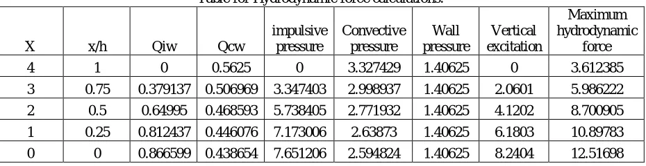
Hydrodynamic pressure = sq root (Impulsive pressure + wall pressure) 2 + convective pressure 2 + vertical excitation 2 Hydrodynamic Calculations are done for five intermediate points of tank wall.
Table for Hydrodynamic force calculations:
X x/h Qiw Qcw
impulsive pressure
Convective pressure
Wall pressure
Vertical excitation
Maximum hydrodynamic
force 4 1 0 0.5625 0 3.327429 1.40625 0 3.612385 3 0.75 0.379137 0.506969 3.347403 2.998937 1.40625 2.0601 5.986222 2 0.5 0.64995 0.468593 5.738405 2.771932 1.40625 4.1202 8.700905 1 0.25 0.812437 0.446076 7.173006 2.63873 1.40625 6.1803 10.89783 0 0 0.866599 0.438654 7.651206 2.594824 1.40625 8.2404 12.51698 Design Parameters:
For all Tanks thickness = 250mm
Base slab thickness = 300mm
Seismic zone = 4
Foundation Type = Mat foundation
Concrete grade = M30
Steel grade = Fe415
Diameter of bar = 12mm
Clear cover = 20mm
Angle of Inclination of soil = 300
Soil unit Weight = 18000 N/m3
Tanks penetration for below ground = Total height of Tank
Roof considered = No. Modellings:
ISSN(Online): 2319-8753 ISSN (Print): 2347-6710
I
nternational
J
ournal of
I
nnovative
R
esearch in
S
cience,
E
ngineering and
T
echnology
(A High Impact Factor & UGC Approved Journal)
Website: www.ijirset.com
Vol. 6, Issue 8, August 2017
Figure.3 - Pressure models on rectangular tanks
In this Figure.3 we could clearly see the modellings of the rectangular tanks. Those are water pressure acting on the base slab of rectangular tank pushing it downwards, water pressure acting on the wall of rectangular tank pushing it outwards, upliftment pressure acting on the base slab of rectangular tank pushing it upwards and earth pressure acting on the wall of rectangular tank pushing it inwards.
Figure.4- Pressure models on circular tanks
In this Figure.4 we could clearly see the modellings of the circular tanks. Those are water pressure acting on the base slab of circular tank pushing it downwards, water pressure acting on the wall of circular tank pushing it outwards, upliftment pressure acting on the base slab of circular tank pushing it upwards and earth pressure acting on the wall of circular tank pushing it inwards.
Discussions:
Coefficients are been taken from the IS code 3370 part 4 and remaining three parts are also been utilized.
ISSN(Online): 2319-8753 ISSN (Print): 2347-6710
I
nternational
J
ournal of
I
nnovative
R
esearch in
S
cience,
E
ngineering and
T
echnology
(A High Impact Factor & UGC Approved Journal)
Website: www.ijirset.com
Vol. 6, Issue 8, August 2017
Remaining formulas are been taken from design philosophy. Analysis alone is been mentioned here not the design and detailing part.
For base projection iterations should be done or we should approach in a quadratic equation way. IV.EXPERIMENTAL RESULTS
Rectangular tanks are considered as wall panels which are intermediate at every 4 or 5 meters. They are having moments at both liquid face and outer face. Here maximum values are been given. Similarly it also contains behaviour of long and short walls. Here behaviour of long wall is been mentioned as it comprises of maximum moments. But circular tank is considered as monolithic wall which comprises moment at only one face at a single point. From table 1 to 4 comparisons of moments between presence and absence of hydrodyamic forces are been mentioned, which are at a condition of fully filled with water. For table 5 comparisons of moments between capacities are mentioned instead of hydrodynamic forces interferences because empty conditions of tanks are been mentioned there, so hydrodynamic forces wont exists without the presence of water. For first five tables moments are determined for five intermediate points from top to bottom. Here negative values of moments shows for liquid face and positive for outer face.
Moments pattern:
We have to analyse the tanks for betterment in results. Here the work starts.
Figure.5- Moments of rectangular tank
ISSN(Online): 2319-8753 ISSN (Print): 2347-6710
I
nternational
J
ournal of
I
nnovative
R
esearch in
S
cience,
E
ngineering and
T
echnology
(A High Impact Factor & UGC Approved Journal)
Website: www.ijirset.com
Vol. 6, Issue 8, August 2017
Figure.6- Moments of circular tank.
In this Figure.6 we could clearly see the moments of the circular tanks. Moments are been replaced with colours for better analysing. Left side picture comprises of horizontal moments of circular tank. And right side of picture comprises of vertical moments of circular tank.
For rectangular tank vertical moment and horizontal moment will be there and for circular Tank vertical moment and hoop tension will be there. Units of moments are KNm and units of hoop tension are in KN. For all tables dia = diameter of circular tank, L & W are length and width of rectangular tanks.
VM = vertical moment, HT = hoop tension, HM = horizontal moment.
No roof considered. These are taken constant for all tanks so as to compare their output. Results are been Tabulated:
Table.1- 1000 cubic meter capacity on ground resting tanks
For table.1 Units of Hoop tension are in KN and Units of bending moment are in KNm.
PRESENCE OF HYDRO DYNAMIC ABSENCE OF HYDRO DYNAMIC
y Frm Tp y/h circular tank rectangular tank circular tank rectangular tank of F.B.(m) dia =21m L=21m, w=16m dia =21m L=21m, w=16m
At V M H T V M H M V M H T V M H M
Heigth 0 0 0.372536 103.9043 0 12.44009 0.289286 80.685 0 9.612 of both 0.75 0.25 1.952087 108.0188 -2.86541 13.97763 1.515857 83.88 -2.214 10.8
tanks 1.5 0.5 4.197235 105.469 5.311498 13.97763 3.259286 81.9 4.104 10.8 3m 2.25 0.75 0.355151 69.62691 -1.7472 8.805904 0.275786 54.0675 -1.35 6.804
3 1 -16.8734 10.25715 -19.1493 3.773959 -13.1027 7.965 -14.796 2.916 y Frm Tp y/h circular tank rectangular tank circular tank rectangular tank of F.B.(m) dia =18m L=23m, w=11m dia =18m L=23m, w=11m
At V M H T V M H M V M H T V M H M
ISSN(Online): 2319-8753 ISSN (Print): 2347-6710
I
nternational
J
ournal of
I
nnovative
R
esearch in
S
cience,
E
ngineering and
T
echnology
(A High Impact Factor & UGC Approved Journal)
Website: www.ijirset.com
Vol. 6, Issue 8, August 2017
Here table.1 shows differences of results between presence and absence of hydrodynamic forces for 1000 cubic meter capacity of on ground resting tanks of both circular and rectangular shapes. For heights of both 3 meters and 4 meters and by varying their dimensions such that it remains with the same capacity.
Table.2- 1000 cubic meter capacity below ground resting tanks.
For table.2 Units of Hoop tension are in KN and Units of bending moment are in KNm.
Here table.2 shows differences of results between presence and absence of hydrodynamic forces for 1000 cubic meter capacity of below ground resting tanks of both circular and rectangular shapes. For heights of both 3 meters and 4 meters and by varying their dimensions such that it remains with the same capacity.
Table.3- 1500 cubic meter capacity on ground resting tanks.
For table.3 Units of Hoop tension are in KN and Units of bending moment are in KNm.
PRESENCE OF HYDRO DYNAMIC ABSENCE OF HYDRO DYNAMIC
y Frm Tp y/h circular tank rectangular tank circular tank rectangular tank of F.B.(m) dia =21m L=21m, w=16m dia =21m L=21m, w=16m
At V M H T V M H M V M H T V M H M
Heigth 0 0 0.198964 55.49333 0 17.47203 0.115714 32.274 0 13.5 of both 0.75 0.25 1.042573 57.69078 4.193288 18.17091 0.606343 33.552 3.24 14.04
tanks 1.5 0.5 2.241664 56.32898 5.59105 16.07427 1.303714 32.76 4.32 12.42 3m 2.25 0.75 0.189679 37.18641 -1.7472 9.434897 0.110314 21.627 -1.35 7.29
3 1 -9.01175 5.478148 -25.8586 5.24161 -5.24109 3.186 -19.98 4.05 y Frm Tp y/h circular tank rectangular tank circular tank rectangular tank of F.B.(m) dia =18m L=23m, w=11m dia =18m L=23m, w=11m
At V M H T V M H M V M H T V M H M
Heigth 0 0 0.188054 23.62434 0 20.19307 0.110933 13.936 0 15.744 of both 1 0.25 1.203066 53.97523 -5.08931 24.29736 0.709689 31.84 -3.968 18.944 tanks 2 0.5 3.327117 93.38529 9.85028 27.74495 1.962667 55.088 7.68 21.632 4m 3 0.75 1.967338 82.49531 5.581825 18.38719 1.160533 48.664 4.352 14.336 4 1 -12.8841 15.54161 -34.6402 6.731025 -7.60036 9.168 -27.008 5.248
PRESENCE OF HYDRO DYNAMIC ABSENCE OF HYDRO DYNAMIC
y Frm Tp y/h circular tank rectangular tank circular tank rectangular tank of F.B.(m) dia =26m L=25m, w=20m dia =26m L=25m, w=20m
At V M H T V M H M V M H T V M H M
Heigth 0 0 0.402827 138.5216 0 16.33702 0.311538 107.13 0 12.6 of both 0.75 0.25 2.053073 133.6534 3.734176 17.27056 1.587808 103.365 2.88 13.32
tanks 1.5 0.5 4.055122 114.9369 5.601264 15.63686 3.136154 88.89 4.32 12.06 3m 2.25 0.75 -0.75194 69.84268 -1.75039 9.335439 -0.58154 54.015 -1.35 7.2
3 1 -19.4538 9.697678 -24.2721 4.901106 -15.0452 7.5 -18.72 3.78 y Frm Tp y/h circular tank rectangular tank circular tank rectangular tank of F.B.(m) dia =22m L=21m, w=18m dia =22m L=21m, w=18m
At V M H T V M H M V M H T V M H M
ISSN(Online): 2319-8753 ISSN (Print): 2347-6710
I
nternational
J
ournal of
I
nnovative
R
esearch in
S
cience,
E
ngineering and
T
echnology
(A High Impact Factor & UGC Approved Journal)
Website: www.ijirset.com
Vol. 6, Issue 8, August 2017
Here table.3 shows differences of results between presence and absence of hydrodynamic forces for 1500 cubic meter capacity of on ground resting tanks of both circular and rectangular shapes. For heights of both 3 meters and 4 meters and by varying their dimensions such that it remains with the same capacity.
Table.4- 1500 cubic meter capacity below ground resting tanks
For table.4 Units of Hoop tension are in KN and Units of bending moment are in KNm.
Here table.4 shows differences of results between presence and absence of hydrodynamic forces for 1500 cubic meter capacity of below ground resting tanks of both circular and rectangular shapes. For heights of both 3 meters and 4 meters and by varying their dimensions such that it remains with the same capacity.
Table.5- Below ground resting tanks of both capacities in empty condition
For table.5 Units of Hoop tension are in KN and Units of bending moment are in KNm.
PRESENCE OF HYDRO DYNAMIC ABSENCE OF HYDRO DYNAMIC
y Frm Tp y/h circular tank rectangular tank circular tank rectangular tank of F.B.(m) dia =26m L=25m, w=20m dia =26m L=25m, w=20m
At V M H T V M H M V M H T V M H M
Heigth 0 0 0.215904 74.24364 0 16.27227 0.124615 42.852 0 12.6 of both 0.75 0.25 1.100389 71.6344 3.719377 17.20212 0.635123 41.346 2.88 13.32
tanks 1.5 0.5 2.173429 61.60288 5.579065 15.57489 1.254462 35.556 4.32 12.06 3m 2.25 0.75 -0.40302 37.43368 -1.74346 9.298442 -0.23262 21.606 -1.35 7.2
3 1 -10.4267 5.197678 -24.1759 4.881682 -6.01809 3 -18.72 3.78 y Frm Tp y/h circular tank rectangular tank circular tank rectangular tank of F.B.(m) dia =22m L=21m, w=18m dia =22m L=21m, w=18m
At V M H T V M H M V M H T V M H M
Heigth 0 0 0.277426 42.88704 0 26.04858 0.162909 25.184 0 20.32 of both 1 0.25 1.611051 71.1696 -6.15321 29.94561 0.946036 41.792 -4.8 23.36 tanks 2 0.5 4.042489 105.0378 11.8962 31.38136 2.373818 61.68 9.28 24.48 4m 3 0.75 1.870642 86.15555 -4.10214 20.10048 1.098473 50.592 -3.2 15.68 4 1 -14.9255 15.01319 -41.2265 7.999171 -8.76451 8.816 -32.16 6.24
1000 cubic meters 1500 cubic meters
y Frm Tp y/h circular tank rectangular tank circular tank rectangular tank of F.B.(m) dia =21m L=21m, w=16m dia =26m L=25m, w=20m
At V M H T V M H M V M H T V M H M
Heigth 0 0 -0.17357 -48.411 0 8.1 -0.18692 -64.278 0 7.56 of both 0.75 0.25 -0.90951 -50.328 1.944 8.424 -0.95268 -62.019 1.728 7.992
tanks 1.5 0.5 -1.95557 -49.14 2.592 7.452 -1.88169 -53.334 2.592 7.236 3m 2.25 0.75 -0.16547 -32.4405 -0.81 4.374 0.348923 -32.409 -0.81 4.32
3 1 7.861629 -4.779 -11.988 2.43 9.027138 -4.5 -11.232 2.268 y Frm Tp y/h circular tank rectangular tank circular tank rectangular tank of F.B.(m) dia =18m L=23m, w=11m dia =22m L=21m, w=18m
At V M H T V M H M V M H T V M H M
Heigth 0 0 -0.1664 -20.904 0 9.4464 -0.24436 -37.776 0 12.192 of both 1 0.25 -1.06453 -47.76 -2.3808 11.3664 -1.41905 -62.688 -2.88 14.016 tanks 2 0.5 -2.944 -82.632 4.608 12.9792 -3.56073 -92.52 5.568 14.688 4m 3 0.75 -1.7408 -72.996 2.6112 8.6016 -1.64771 -75.888 -1.92 9.408
ISSN(Online): 2319-8753 ISSN (Print): 2347-6710
I
nternational
J
ournal of
I
nnovative
R
esearch in
S
cience,
E
ngineering and
T
echnology
(A High Impact Factor & UGC Approved Journal)
Website: www.ijirset.com
Vol. 6, Issue 8, August 2017
Here table.5 shows differences of results between 1000 cubic meter capacity and 1500 cubic meter capacity of below ground resting tanks of both circular and rectangular shapes. For heights of both 3 meters and 4 meters and by varying their dimensions such that it remains with the same capacity. Here they are been considered for tank at empty condition means without water and without hydrodynamic forces.
Table.6- Base slab moments for both capacity tanks
1000 cubic meters 1500 cubic meters height =3 height =4 height =3 height =4 dia =21m L=21m, w=16m dia =18m L=23m, w=11m dia =26m L=25m, w=20m dia =22m L=21m, w=18m Maximum
pressure 14715 14715 19620 19620 14715 14715 19620 19620 Bending
Moment 4905 4905 6540 6540 4905 4905 6540 6540
For table.6 Units of pressure are in Newtons. Units of bending moment are in KNm.
Here table.6 shows maximum pressure and bending moments at base slab of tanks for both capacities and of both shapes. Here height 3 meters and height 4 meters are been considered and by varying their dimensions such that it remains with the same capacity.
Table.7- Uplift analysis for both capacity tanks
1000 cubic meters 1500 cubic meters
height =3 height =4 height =3 height =4 dia =21m
L=21m,
w=16m dia =18m
L=23m,
w=11m dia =26m
L=25m,
w=20m dia =22m
L=21m, w=18m Upward
force
1461052
9 10877328
1073426
6 8190369
2239618
5 16186500
1603513
8 12236994 downward
force 2805099 5643000 2086459 4488500 4238450 8005000 3068207 6246000 Total
upliftment
1180543
0 5234328 8647807 3701869
1815773
4 8181500
1296693
1 5990994 Projection 0.350791 1.2 0.306355 1.1 0.424875 1.5 0.365606 1.3
For table.7 All force units are in Newtons. Units of Projection are in meters.
ISSN(Online): 2319-8753 ISSN (Print): 2347-6710
I
nternational
J
ournal of
I
nnovative
R
esearch in
S
cience,
E
ngineering and
T
echnology
(A High Impact Factor & UGC Approved Journal)
Website: www.ijirset.com
Vol. 6, Issue 8, August 2017
Graphs for better understandings: Graph.1-
Graph.1 shows comparison of moments between presence and absence of Hydrodynamic forces for rectangular tank of 21m*16m*3m
Here graph.1 shows comparison of vertical moments and horizontal moments between presence and absence of Hydrodynamic forces for rectangular tank of dimensions 21m*16m*3m which is of capacity 1000 cubic meters and which is rested on ground.
Graph.2-
Graph.2 shows comparison of moments between presence and absence of Hydrodynamic forces for circular tank of 21m*3m
-25 -20 -15 -10 -5 0 5 10 15 20
0 0.75 1.5 2.25 3
vertical moment of rectangular tank in the presence of hydrodynamic forces
Horizontal moment of rectangular tank in the presence of hydrodynamic forces
vertical moment of rectangular tank in the absence of hydrodynamic forces
-40 -20 0 20 40 60 80 100 120
0 0.75 1.5 2.25 3
vertical moment of circular tank in the presence of hydrodynamic forces
Horizontal moment of circular tank in the presence of hydrodynamic forces
vertical moment of cirular tank in the absence of hydrodynamic forces
ISSN(Online): 2319-8753 ISSN (Print): 2347-6710
I
nternational
J
ournal of
I
nnovative
R
esearch in
S
cience,
E
ngineering and
T
echnology
(A High Impact Factor & UGC Approved Journal)
Website: www.ijirset.com
Vol. 6, Issue 8, August 2017
Here graph.2 shows comparison of vertical moments and horizontal moments between presence and absence of Hydrodynamic forces for circular tank of dimensions 21m dia* 3m height which is of capacity 1000 cubic meters and which is rested on ground.
V. CONCLUSIONS
The conclusions of this paper are follows:
1. Vertical moments of Rectangular tank are 13.46 %more than cylindrical tank.
2. Hoop tensions of circular tanks are 6.73 times more than horizontal moments of Rectangular tank. 3. When height decreases moments also decreases by 30.52%.
4. Presence of Hydrodynamic pressure creates moments 28.77% more in circular Tanks and 29.35% more in Rectangular Tanks.
5. Per unit meter increase in height at Base slab, Maximum pressure increases 4905N more and Base slab moments increases 1635Nm more.
6. Base pressures and moments are similar for all tanks of same height irrespective to their capacities and other dimensions, as water been loaded from top to bottom.
7. Upliftment is been counteracted by base projection as soil from base projection up to ground level acts as dead weight to the tank.
8. Projections for rectangular tanks are 3.42 times more required than circular tanks of same height.
REFERENCES
[1] M. Bhandari, Karan Deep Singh, “Economic Design of Water Tank of Different Shapes With Reference To IS: 3370 2009”, International Journal Of Modern Engineering Research (IJMER), vol.4, issue 12, Dec.2014.
[2] A. Dogangun and R. Livaoglu, “A Comparative study of the seismic analysis of rectangular tanks according to different codes”, The 14th World Conference on Earthquake Engineering October 12-17, 2008, Beijing, China.
[3] Viral Desani, Dipak Jivani, “Parametric Study of Hydrodynamic Pressure for Ground Rested RC Tank”, International Journal of Advance Engineering and Research Development (IJAERD), Volume 1, Issue 11, November -2014.
[4] yash chaliawala, gunvant solanki, Anuj.K.Chandiwala, “Comparative Study of Cantilever and Counter fort Retaining wall”, International Journal of Advance Engineering and Research Development (IJAERD), Volume 2, Issue 12, December -2015.
[5] Punith C ,Usha, Jayalakshmi Raju, M. Adil Dar, in April 2015, “Finite Element Analysis of Underground Water Tank with different Safe Bearing Values of Soil”, SSRG International Journal of Civil Engineering (SSRG-IJCE) – EFES, April 2015.
[6] S. A. Halkude, A. A. Perampalli, “Analysis of Water Tank on Sloping Ground”, International Journal of Engineering and Innovative Technology (IJEIT), Volume 3, Issue 5, November 2013.
[7] Riyaz Sameer , Mundhada , Snehal Metkar, in December 2012, “Compariison of r.c.c. and prestressed concrete ciircular water tanks”, International Journal of Emerging Technology and Advanced Engineering (IJETAE), Volume 2, Issue 12, December 2012.
[8] Snehal Wankhede, P. J. Salunke, N. G. Gore,“Optimization of water storage tank”, International Journal of Engineering and Technical Research (IJETR) , Volume-3, Issue-4, April 2015.
[9] Thalapathy.M, Vijaisarathi.R.P, Sudhakar.P, Sridharan.V, Satheesh.V.S, “Analysis and Economical Design of Water Tanks”, International Journal of Innovative Science, Engineering & Technology (IJISET), Vol. 3 Issue 3, March 2016.
[10] Tonne V. R, Mohite P. M, “Optimization and improvement in stability of counter fort retaining wall with relief shelf”, International Journal of Research in Engineering and Technology (IJRET), Volume 4, Issue 4, Apr-2015.
[11] Mehul S. Kishori, Chirag N. Patel, in May 2015, “Parametric Study of Rectangular Water Tank using Different Methodology”, International Journal for Scientific Research & Development (IJSRD), Vol. 3, Issue 05, 2015.