wind energy conversion systems
Matías Díaz
1, Roberto Cárdenas
1, Félix Rojas
2, Jon Clare
31
Electrical Engineering Department, University of Chile, Chile
2
Electrical Engineering Department, Technical University of Munich, Germany
3
Power Electronic and Machine Control Group, The University of Nottingham, United Kingdom E-mail: [email protected]
Abstract:The high penetration of energy from wind energy conversion systems (WECSs) can have a significant influence on the stability, power quality and reliability of power systems. Therefore several countries have developed stringent grid codes in recent years in order to enhance the overall stability of power systems. In these grid codes, the capacity to fulfil low-voltage ride through (LVRT) requirements is considered an important issue for the control of WECSs. Therefore in this study, a novel voltage sag/ swell generator (VSG) based on a 4-leg matrix converter is presented. This VSG can be used to generate the symmetrical and asymmetrical faults required to test LVRT algorithms in a laboratory environment. The performance of the VSG is experimentally demonstrated and compared with the operation of other VSGs conventionally used for LVRT studies.
1
Introduction
The huge penetration of generation from wind energy conversion systems (WECSs) into the utility has a significant influence on the stability, power quality and availability of conventional power systems [1]. To avoid stability problems and to regulate the interconnection of WECS to generation and transmission systems, stringent grid codes have been enforced in several countries, where renewable energies have a considerable impact on the grid. A detailed review of international grid code requirements is presented in [1,2].
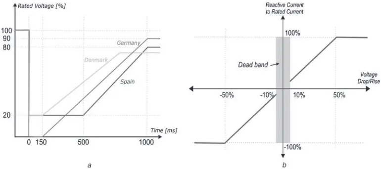
Nowadays WECSs, and in general all renewable energy systems (RESs), have to fulfil grid-codes when connected to the grid. A main concern is the low-voltage ride through (LVRT) capability of grid connected RESs, because of voltage sags, which are the most prevalent disturbances in an electrical power system. For example, recent surveys indicate that 92% of all disturbances correspond to voltage sags [3]. Moreover, 88% of voltage sags are asymmetrical [4]. Fig. 1a shows the LVRT requirements from different national grid codes [3, 5]. According to Fig. 1a, the WECSs must stay connected for grid-voltage sags when the grid voltage is within specified boundaries. In Fig.1b, the requirement for reactive power is shown. Reactive power has to be supplied to the grid when the voltage drops, to support the grid voltage.
For research purposes, LVRT algorithms have to be validated using a VSG. Hence, devices to generate grid-voltage sag are required. According to the norm of the International Electro Technical Commission IEC
61000-4-11 [6], a VSG is a device able to emulate grid-voltage sag conditions, either in the field or in a laboratory test environment. In addition, a custom VSG should meet the following requirements:
† Capability to emulate symmetric grid-voltage sags. † Capability to emulate asymmetrical grid-voltage sags. † Capability to control the depth and duration of the
emulated grid-voltage sag.
† Capability to provide a controllable recovery voltage
profile.
A VSG must provide voltage sags of between 0.5 and 30 cycles in duration and the depth can vary between 10 and 90% of the nominal value [6]. The main desirable feature in a VSG is simple programmability in the magnitude, duration and type of voltage sag [4]. Furthermore, some power quality issues are associated with the VSG itself. At the point of common coupling (PCC) with the electrical power system, the harmonic current should be limited to 5% to avoid unacceptable harmonic voltages [7]. In applying this limit, the harmonic currents should be determined over 10 min and frequencies up to 50 times the fundamental grid frequency should be considered [8,9].
There are four main types of voltage-sag generators [10,11]: shunt impedance-based, transformer-based, generator-based and full converter (back-to-back topology)-based VSGs. The topology of each one is shown in Fig.2.
relatively high power are simple to implement. However, only symmetrical faults can be synthesised.
Commercially available VSGs are usually full converter based, and are offered by a few international manufacturers. This topology is shown in Fig.2band has bidirectional power
flow, avoiding the dissipation of energy in passive components. The main drawback of this topology is the high cost. The transformer-based VSG has been recently discussed in the literature [10–13]. It is composed of a step-down auto-transformer with several taps, with switching devices being connected to generate the voltage sags. The typical transformer-based VSG structure is shown in Fig.2c.
The switching devices can be relays, thyristors or IGBTs. It is complex to coordinate the switching time of relays and this
may produce voltage interruptions and oscillations at the output. It is possible to partially solve these problems by replacing the relays with thyristors. In this case, the control system is more complex to implement because a short circuit may be produced when thyristors in different taps are conducting simultaneously. Thyristors can be replaced by forced commutation devices such as IGBTs. Nevertheless additional complexity is added to the system because IGBTs cannot be used to interrupt inductive currents unless clamps such as varistors and/or zero current detectors are provided. Generally, however, this type of voltage-sag generator is a low cost solution [10].
The shunt impedance-based VSG generates grid-voltage sags by switching impedances in parallel with the line, as
Fig. 1 LVRT requirements from different national grid codes
aLVRT requirements for Germany, Denmark and Spain
bReactive power requirement as a function of the grid voltage for the Spanish grid code
Fig. 2 Four main types of voltage-sag generators
[image:2.595.104.489.55.226.2] [image:2.595.134.466.468.722.2]proposed VSG has a very simple design and control and is suitable for most research and development tests to evaluate the behaviour of WECS under voltage-sag conditions. In the experimental section of this paper, tests with 4-wire isolated load and tests feeding a grid-connected WECS are presented to verify the performance of the proposed VSG.
Most of the applications of VSGs are related to WECS development. However, in some applications, particularly in low-voltage micro-grids, 4-wire loads and converters are present. According to [16], some power quality issues have been addressed in low-voltage micro-grids to regulate the unbalance and harmonic distortion levels [17]. Therefore in the proposed VSG, a 4-leg MC has been used to enable experimental testing of control systems for micro-grids with programed sag disturbances in 4-wire systems.
This paper is structured as follows. In Section 2, the implementation of a MC-based VSG is described. The experimental setup is presented in Section 3. Simulation and experimental results for the proposed MC-based VSG,
flexible and available at the power electronic lab where the experimental system was implemented. Moreover a 4-leg MC can be used to emulate other grid disturbances. For instance, it is relatively simple to emulate phase jumps using an MC.
3
MC-based VSG
MCs have been extensively studied in the literature [18,19]. This type of converter provides sinusoidal input/output currents, bidirectional power flow, controllable input displacement factor and variable frequency/voltage output voltages. When compared with back-to-back converters, the MC has some advantages [20, 21]. For instance, the MC does not need a DC-link capacitor, allowing a compact design. As a result of the absence of electrolytic capacitors MCs also can be more robust and reliable than back-to-back converters [18]. Owing to the aforementioned advantages, MCs are well suited for use as a full converter VSG.
Fig. 3 Proposed VSG
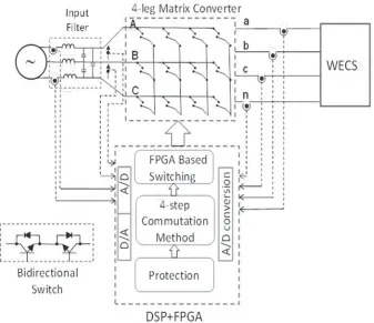
[image:3.595.104.494.477.743.2]The proposed topology is shown in Fig.4. The 4-leg MC is composed of 12 bidirectional switches, which can be used to connect any input phase to a particular output. There are two restrictions, which have to be considered in the operation of the switches:
Two input phases cannot be short circuited.
Owing to the inductive nature of the load, an output phase cannot be opened.
These restrictions are fulfilled using one of the commutation methods discussed in the literature. In this work, the well-known 4-step commutation method [22] has been implemented in an FPGA board. The control of the A/D and D/A converters and the logic required for overcurrent protection is also implemented in this FPGA. This allows more noise immunity, simplicity when redesign is required and higher integration. In Fig. 4, the input current and the output voltages are also measured for general interest. However, these measurements are not required for the control of the proposed VSG.
One of the principal disadvantages of full converter-based VSGs are the complexity of the required control system. In back-to back converters, space vector modulation (SVM) algorithms (or something equivalent) are required to control the pulse-width modulation (PWM) rectifier and the front-end converter [23]. Moreover, for synthesising grid-voltage sags, the regulation of the positive and negative sequence voltages is required, increasing the complexity of the modulation algorithm [24]. If 4-leg converters are used, three-dimensional modulation algorithms are required to regulate the positive, negative and zero sequence component of the output voltage [25] making the required control system even more complex.
In the proposed VSG, the voltages sags are achieved using the simple methodology described below, which avoids the use of a complex modulation algorithm.
3.1 Proposed methodology for voltage-sag generation using a 4-leg MC
A 4-leg MC has 12 bidirectional switches distributed as shown in Fig. 4. The input voltages are usually designated using uppercase, for example, ‘A’,‘B’and‘C’, whereas the output voltages are designated using lowercase, that is, ‘a’, ‘b’and‘c’.
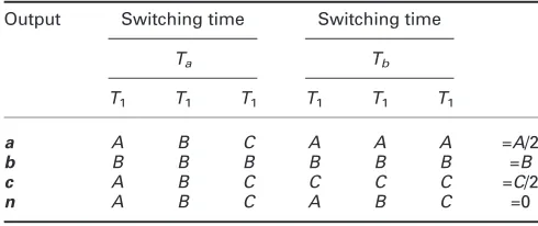
Representing each switch state of the MC with logic 1 for closed operation and with logic 0 for open operation, it is possible to obtain any of the input voltages at the outputs. For example, Table 1 shows the combination of switching states used to impose the A, B andC input voltages at the a,bandcoutputs, respectively.
Therefore, if the switching pattern represented by Table1is used, the input and output voltages are identical. When a fraction of the input voltage or a null voltage is required at the output terminals, a sample time ‘Ts’ must be defined.
During the sample time, a combination of different phases is switched in order to create the desired output values on average.
3.1.1 Single-phase grid-voltage sag: To create a single-phase voltage sag, the synthesis is done over two
[image:4.595.131.468.55.346.2]Fig. 4 Proposed VSG based on a 4-leg MC
Table 1 MC representation
Input A 1 0 0 0 MC
B 0 1 0 0
C 0 0 1 0
[image:4.595.308.553.732.778.2]in Table 2. Notice that in this case, the grid-voltage sag is produced in phase‘c’.
During sample periodTa, the average voltages at the four outputs are given by the following equation
Va=VA
3 + VA
3 + VA
3 =Va, Vb= VB
3 + VB
3 + VB
3 =VB
andVc=Vn=VA
3 + VB
3 + VC
3 =0 (1)
Correspondingly for the periodTb, they are given by (1)
Vn = VA
3 + VB
3 + VC
3 =0, Va= VA
3 + VA
3 + VA
3 =VA,
Vb =VB
3 + VB
3 + VB
3 =VB andVc= VC
3 + VC
3 + VC
3 =VC (2)
If, for example, the timesTaandTbhave the same value, the output voltageVcwill have 50% of the amplitude of the phase Cinput voltage. The other output voltages are equal to the input voltage, with zero voltage at the output neutral line. More generally, the voltage on the phase with the sag is given by (3) and different values of sag can be created by adjustingTaandTb
Vc=VCTb/(Ta+Tb) (3)
3.1.2 Two-phase grid-voltage sag: The procedure to generate a two-phase grid-voltage sag is an extension of that for the single-phase sag and is illustrated in Table3 (in this case for sags on output phasesaandc).
During sample periodTa, the average voltages at the four outputs are given by the following equation
Va =Vc=Vn=VA
3 + VB
3 + VC
3 =0 and
Vb =VB
3 + VB
3 + VB
3 =VB
(4)
Correspondingly for period Tb, they are given by the following equation
Vn=VA
3 + VB
3 + VC
3 =0, Va = VA
3 + VA
3 + VA
3 =VA,
Vb=VB
3 + VB
3 + VB
3 =VB and Vc= VC
3 + VC
3 + VC
3 =VC (5)
Va= VATb
Ta+Tb and Vc= VCTb
Ta+Tb (6)
Again, different values of sag can be created by adjustingTa andTb:
Phase jumps can be created by changing the switching for periodTbin (5). For instance
Vn=VA
3 + VB
3 + VC
3 =0, Va= VA
3 + VA
3 + VB
3 =VA,
Vb=VB
3 + VB
3 + VC
3 =VB and Vc= VC
3 + VC
3 + VA
3 =VC (7)
Hence the average voltages on the output phases are given by the following equation
Va=
2 3VA+
1 3VB
Tb
Ta+Tb ,
Vb=5
6VB+ 1
6VC and Vc= 2 3VC+
1 3VA
Tb
Ta+T
b
(8)
Using (8), the phase of the output can be changed. For instance in (8), the phase of output voltage ‘a’ is jumped from 0° to 30° with a voltage-sag magnitude of about 29% inVa.
3.2 Maximum output value to be synthesised: As discussed in several papers by Alesina and Venturini [26–
28], when the input/output frequencies are not correlated and injection of triple harmonics is not considered, the maximum amplitude which can be synthesised at the MC output (without producing low-frequency harmonic distortion) is 50% of that of the input voltage. This is further demonstrated using Fig. 5a. Alesina and Venturini also demonstrated in [27] that the achievable ratio between the input and voltages amplitudes could be increased to 0.8666 if triple harmonics are added to the target output signal.
[image:5.595.307.552.78.181.2] [image:5.595.41.286.79.180.2]phase and frequency, the output signal cannot be outside the envelope. Notice that in the example of Fig.5b, input phases A andB are each connected for Ts/6 to the output and the
phaseCis connected for the rest of the time 4 6Ts
, that is,
Vc= VA
6 + VB
6 + VC
6 + 3VC
6 = VC
2 (9)
Therefore the output fundamental is equal to 0.5VC. It should
be noted that in Fig. 5b an unusually large value of Ts has
been used for clarity of illustration – much higher frequency switching is used in practice.
3.3 Generating grid-voltage swell conditions: If the output voltage has the same frequency and phase, the maximum voltage ratio q= 1, this implies that the maximum amplitude which can be synthesised at the MC output is equal to the maximum input voltage. Therefore, to test swell conditions at the PCC of the WECS, it is
Fig. 5 Input and voltages amplitudes
aMaximum amplitude synthesised at the MC output bIdentical input/output frequencies
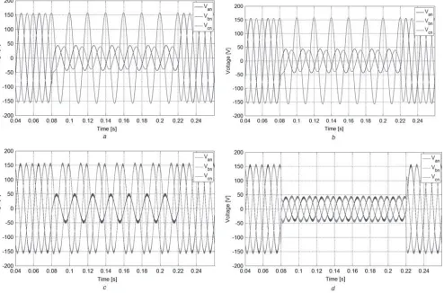
Fig. 6 Simulation results for proposed MC-based VSG
[image:6.595.106.491.54.206.2] [image:6.595.54.548.397.723.2]The main idea is to operate the MC to obtain the WECS nominal voltage at the PCC using a ratio q< 1. When a swell condition is required, the MC synthesises the required voltage level at the PCC by increasing the value of q. Therefore, for an input voltage of Vmax= 380 V, the
maximum swell magnitude that can be reached at the PCC is equal toVswell max= 380 V.
4
Experimental system
A 3 kVA MC-based VSG has been implemented and is controlled using a high performance DSP-FPGA combination. The DSP is based on the TI TMS320C67 processor, capable of 1350MFLOPS. For data acquisition
measure currents and voltages. Further details concerning the control of the WECS converter are considered outside the scope of this paper.
The performance of the VSG has also been tested considering 4-wire systems. In this case, a 60Ω three-phase load is connected at the PCC instead of the RES. Moreover, the fourth leg of the MC is used to regulate the load neutral point.
Using the same DSP-FPGA-based interface, a 3-kVA transformer-based VSG is implemented in order to compare results. This VSG is based on a combination of relays and single-phase auto-transformers [11], that allow switching of one (or two) grid phase voltages from rated voltage to a smaller voltage to create a sag.
Fig. 7 Grid-voltage-sag condition generated by the proposed 3-phase 4-wire
a30% Grid-voltage dip Type C using MC-based VSG bAmplified view of Fig.7a
[image:7.595.41.287.70.161.2] [image:7.595.47.553.410.723.2]5
Simulation and experimental results
In this section, simulation and experimental results are discussed to validate the proposed 3-phase 4-leg MC-based VSG. A comparison between the proposed VSG, a transformer-based VSG and a commercial MX series AC programmable power source is presented. Unbalanced grid voltage sags have been performed for the three different VSGs and compared under the same load conditions. Grid connected and standalone operation has been performed using the MC.
5.1 Simulation results for MC-based VSG
A MATLAB/SIMULINK model has been developed to validate the proposed methodology for voltage-sag generation using a 4-leg MC. Simulations have been realised in order to verify the operation of the proposed VSG working with resistive, inductive and capacitive loads. Fig. 6a shows the MC output voltage waveforms for a two-phase sag voltage (a type C dip, according with the classification discussed in [29]). In this case, a load of 5Ω
has been considered. The MC voltage-sag waveform for the same disturbance, but feeding a capacitive load of 20μF
and Xc= 160Ω, is presented in Fig. 6b. Furthermore, tests feeding an inductive load of 5 mH have been also carried out. Figs.6canddpresent MC output voltage waveforms for a 30% dip type B and 30% symmetrical sag, respectively. Finally, different tests are presented and summarised in Table 4. In all the cases, the expected performance of the MC-based VSG is very good for any load condition and the harmonic distortion is lower than the limits given in [7].
5.2 Grid-voltage-sag disturbances for 4-wire loads
For these tests, all VSGs are connected to a 4-wire three-phase resistive load. The fourth leg of the MC-based VSG is connected to the neutral point of the load. In the case of the Ametek Power Source, a delta-star transformer in used in order to obtain a fourth wire to connect the load neutral point.
Fig.7ashows the grid-voltage-sag condition generated by the proposed 3-phase 4-wire MC-based VSG for a voltage dip Type C. Phasesa andcreduce their voltage to 30% of the rated value. In Fig.7b, an amplified view of the dip is shown. At the desired fault time, the MC changes the amplitude of the output voltage at phase a andc – from the rated value
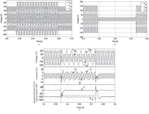
Fig. 8 Symmetrical and swell testing for the proposed MC-based VSG
a50% Grid-voltage swell using MC-based VSG b20% Symmetrical sag using MC-based VSG cWECS behaviour for two phases 50% grid-voltage sag Up: Grid voltage
Medium: Grid currents
[image:8.595.47.547.331.713.2]greatly improved compared with the transformer-based VSG, and also it has better quality than the MC-based VSG. This is mainly because the modulation algorithms can compensate some of the non-linearities using closed-loop control, whereas the proposed MC-based VSG does not require a complex modulation strategy and operates open loop. Nevertheless, the proposed MC-based VSG achieves good output voltage waveforms and is able to emulate various types of voltage faults.
5.3 Symmetrical and swell testing for the proposed MC-based VSG
The proposed VSG is also able to perform voltage swells. The output voltage waveform for two phases swell is shown in Fig.8a. When the voltage swell occurs, the MC changes its output voltage in phases ‘a’ and ‘c’, from the rated value (110 Vrms) to the swell condition (155 Vrms). The
high-voltage condition duration time is 320 ms, no peaks or transient effects and low harmonic distortion (THD≃4.55%) are present in the waveforms.
As can be observed in Fig. 8b, the proposed MC-based VSG can be used to perform symmetrical voltage sags. At the desired time, the three output phases of the MC-based VSG drop from the rated value (110 Vrms) to the sag
condition (25 Vrms), for 240 ms. In the fault period, the
harmonic distortion reaches 8.32%. When the voltage sag recovers, the MC output voltages come back to the rated value without transient effects or overshoot.
5.4 WECS connected test for the proposed 3-phase 4-leg MC
One of the principal functionalities of a VSG is to test LVRT in a WECS. To test LVRT, the proposed MC-based VSG is connected to a WECS emulation.
To accomplish LVRT requirements, a control strategy based on [11, 18] is implemented in the PWM converter implementing the emulation. In steady state, the WECS control system works at unity power factor, 200 V (peak value) at the PCC and the active power is set to 1 kW. Results are shown in Fig.8c.
At the sag appearance, phasesa andc of the MC-based VSG drop from the rated value (200 Vpeak) to the sag
condition (100 Vpeak). During the failure period, the active
power delivered to the grid is set to 0 kW, and the WECS emulation starts to support the grid voltage through reactive power injection. When the fault is over, the control system comes back to the state-steady condition. As can see in Fig. 8c, the line currents are slightly distorted and
the voltage sags generated do not present undesired transient effects or overshoots. During the grid-voltage-sag conditions, THD reaches 8.32%. In contrast, the transformer-based VSG exhibits a number of undesirable transient and distortion effects.
Additional experimental results show that the proposed MC is able to produce grid-voltages with symmetrical sag and swell conditions .The proposed VSG can be used in RESs to test LVRT requirements for grid-connected converters.
The Ametek Power Source presents the best behaviour generating grid-voltage sags, achieving THD lower than 1% in all cases. However, the simplicity in synthesising output voltages in the proposed MC is a major advantage in comparison to the closed-loop modulation waveform control in the power source.
The difference in voltage harmonic distortion level throughout the sag condition is mainly because of the lack of closed-loop modulation in the MC-based VSG. However, the use of a second-order output filter and switching frequency of 12.5 kHz ensures low-harmonic voltage distortion. In all the cases, the results of the proposed VSG meet the international standards and the harmonic content of the output voltage is relatively independent of the load condition.
7
Acknowledgment
The authors thank CONICYT for the financial support through grants 1140337 and FONDEQUIP EQM120111.
8
References
1 Altn, M., Goksu, O., Teodorescu, R., Rodriguez, P., Jensen, B.-B., Helle, L.:‘Overview of recent grid codes for wind power integration’. 12th Int. Conf. on Optimization of Electrical and Electronic Equipment (OPTIM), 2010, 2010, pp. 1152–1160
2 Iov, N.C.F., Hansen, A., Sørensen, P.:‘Mapping of grid faults and grid codes,’Risø-R-1617(EN) 41 p
3 Senturk, O.S., Hava, A.M.:‘A simple sag generator using SSRs’. 2010 IEEE Energy Conversion Congress and Exposition, 2010, pp. 4049–4056
4 Cárdenas, R., Peña, R., Alepuz, S., Asher, G.:‘Overview of control systems for the operation of DFIGs in wind energy applications’, IEEE Trans. Ind. Electron., 2013,60, (7), pp. 2776–2798
5 Tsili, M., Papathanassiou, S.: ‘A review of grid code technical requirements for wind farms’,IET Renew. Power Gener., 2009,3, (3),
pp. 308
6 ‘Electromagnetic compatibility (EMC) - Part 4–11: Testing and measurement techniques – voltage dips, short interruptions and voltage variations immunity tests,’IEC std 61000-4-11, 2004 7 ‘IEEE Standard for Interconnecting Distributed Resources with Electric
8 ‘IEEE Recommended Practice for Monitoring Electric Power Quality.’ pp. vol., no., p. i, 1995
9 ‘Electromagnetic compatibility (EMC)– Part 21: Measurement and Assessment of Power Quality Characteristics of grid Connected Wind Turbines,’IEC std 61400-21
10 Yang, Y., Blaabjerg, F., Zou, Z.: ‘Benchmarking of voltage sag generators’. IECON 2012 – 38th Annual Conf. on IEEE Industrial Electronics Society, 2012, pp. 943–948
11 Wessels, C., Lohde, R., Fuchs, F.W.:‘Transformer based voltage sag generator to perform LVRT and HVRT tests in the laboratory’. Proc. of 14th Int. Power Electronics and Motion Control Conf., EPE-PEMC 2010, 2010, pp. T11–8–T11–13
12 Veganzones, F.W., Sanchez, J.A., Martinez, S., et al.: ‘Voltage dip generator for testing wind turbines connected to electrical networks’, Renew. Energy, 2011,36, (5), pp. 1588–1594
13 Hu, S., Li, J., Xu, H.:‘Comparison of voltage sag generators for wind power system’. 2009 Asia-Pacific Power and Energy Engineering Conf., 2009, pp. 1–4
14 Gabe, I.J., Grundling, H.A., Pinheiro, H.:‘Design of a voltage sag generator based on impedance switching’. IECON 2011 – 37th Annual Conf. of the IEEE Industrial Electronics Society, 2011, pp. 3140–3145
15 Chung, Y.H., Kwon, G.H., Park, T.B., Lim, G.Y.:‘Voltage sag and swell generator with thyristor controlled reactor’. Proc. Int. Conf. on Power System Technology, 2002, vol. 3, pp. 1933–1937
16 Guerrero, J.M., Loh, P.C., Lee, T.-L., Chandorkar, M.: ‘Advanced control architectures for intelligent microgrids–part II: power quality, energy storage, and AC/DC microgrids’,IEEE Trans. Ind. Electron., 2013,60, (4), pp. 1263–1270
17 Oe, S.P., Christopher, E., Sumner, M., Pholboon, S., Johnson, M., Norman, S.A.: ‘Microgrid unbalance compensator – Mitigating the negative effects of unbalanced microgrid operation’. IEEE PES ISGT Europe 2013, 2013, pp. 1–5
18 Wheeler, P.W., Clare, J.C., Apap, M.,et al.: ‘An integrated 30 kW matrix converter based induction motor drive’. IEEE 36th Conf. on Power Electronics Specialists, 2005, 2005, pp. 2390–2395
19 Cardenas, R., Juri, C., Pena, R., Clare, J., Wheeler, P.:‘Analysis and experimental validation of control systems for four-leg matrix
converter applications’, IEEE Trans. Ind. Electron., 2012, 59, (1),
pp. 141–153
20 Friedli, T., Kolar, J.W., Rodriguez, J., Wheeler, P.W.:‘Comparative evaluation of three-phase AC–AC matrix converter and voltage DC-link back-to-back converter systems’,IEEE Trans. Ind. Electron., 2012,59, (12), pp. 4487–4510
21 Friedli, T., Kolar, J., Rodriguez, J., Wheeler, P.: ‘Comparative evaluation of three-phase AC-AC matrix converter and voltage DC-link back-to-back converter systems’,IEEE Trans. Ind. Electron., 2011,PP, (99), pp. 1
22 Wheeler, P. W., Rodriguez, J., Clare, J. C., Empringham, L., Weinstein, A.: ‘Matrix converters: a technology review’, IEEE Trans. Ind. Electron., 2002,49, (2), pp. 276–288
23 Cardenas, R., Pena, R., Perez, M., Clare, J., Asher, G., Vargas, F.: ‘Vector control of front-end converters for variable-speed wind– diesel systems’, IEEE Trans. Ind. Electron., 2006, 53, (4),
pp. 1127–1136
24 Zeng, R., Nian, H., Zhou, P.:‘A three-phase programmable voltage sag generator for low voltage ride-through capability test of wind turbines’. 2010 IEEE Energy Conversion Congress and Exposition, 2010, pp. 305–311
25 Cárdenas, R., Juri, C., Peña, R., Wheeler, P., Clare, J.:‘The application of resonant controllers to four-leg matrix converters feeding unbalanced or nonlinear loads’, IEEE Trans. Power Electron., 2012, 27, (3),
pp. 1120–1129
26 Alesina, A., Venturini, M.G.B.: ‘Analysis and design of
optimum-amplitude nine-switch direct AC-AC converters’, IEEE Trans. Power Electron., 1989,4, (1), pp. 101–112
27 Alesina, A., Venturini, M.: ‘Intrinsic amplitude limits and optimum design of 9-switches direct PWM AC-AC converters’. PESC’88, 1988, pp. 1284–1291
28 Alesina, A., Venturini, M.: ‘Solid-state power conversion: a Fourier analysis approach to generalized transformer synthesis’,IEEE Trans. Circuits Syst., 1981,28, (4), pp. 319–330
29 Bollen, M.H.J.: ‘Characterisation of voltage sags experienced by three-phase adjustable-speed drives’,IEEE Trans. Power Deliv., 1997,