© 2017, IRJET | Impact Factor value: 5.181 | ISO 9001:2008 Certified Journal | Page 964
VOLTAGE BALANCING IN SOLAR BASED DC MICRO-GRID SYSTEM
Darshana Baghel
1, Mr. Ram Ratan Tiwari
21
PG Scholar,
2Lecturer,Electrical Department, LDRP-ITR, Gandhinagar, Gujarat, India
---***---Abstract -A DC micro grid system is a novel power system
that introduce a huge amount of solar power using distributed photovoltaic generation units. The redox flow battery is an important component which help in rapid charge-discharge even under the fluctuating condition of power generation and consumption, supply-demand adjustment takes place in the micro grid system. In micro-grid power transmit with the help of two wire is generally not suitable for the requirements of the input voltage levels of different power converters and loads. In order, to fulfil the demand, a micro-dc grid introduced half-bridge voltage balancer, which convert a two-wire system into a three-wire system in which neutral line exist. Here control strategy and dual buck half-bridge voltage balancer itself are proposed to avoid the “shoot-through” problem which existed in bridge type converters. “shoot-through” problem can be solved with the help of Complementary driving technology.
Key Words:DC micro grid, Voltage Balancer and RF
battery…
1. INTRODUCTION
The increasing demand for development of power from renewable energy (Solar energy) has led to creation of Micro-dc grid. A micro-grid can be defined as a group of local electrical sources and loads that are operated in correction to and in synchronism with conventional grid but can also be operated in disconnected and autonomous system.A dc-micro grid is depending upon on some interfacing converter, such as grid-connected inverter, bidirectional converter and dc converter, and voltage-balancer and so on. PV modules generate DC electric power. The main components of a micro grid are: (i) distributed generation sources such as photovoltaic panels, small wind turbines, fuel cells, diesel and gas micro turbines, etc., but here we only considered PV panels, (ii) distributed energy storage devices such as batteries, super capacitors, etc., and (iii) critical and non-critical loads.[3] Here silicon photovoltaic (Si-PV)units, copper indium gallium selenide photovoltaic (CIGS-PV) units, concentrator photovoltaic (CPV) units, and a redox flow battery are used to check the feasibility of the system. The power should be converted to AC that is synchronized with commercial grids to be transmitted and distributed
to demand sites. To reduce energy dissipation through the transmission, the power is sent near the demand site after being raised the electric voltage to 66 kV or higher. A micro-dc grid generally operates on one voltage level in two-wire distribution system, and it is impossible to supply some types of loads at half voltage such as dc/ac inverters needing a neutral line, converters with input voltage balancing like half- bridge converter and three-level half-bridge converter, and so on. Shoot-through problem which existed in bridge type converters can be solved by dual buck half bridge voltage balancer. For meeting the characteristic of the proposed voltage balancer, a control strategy of respectively driving the two bridge legs of the proposed voltage balancer to work for a high efficiency is also presented. When a dc-micro grid is used in residential and work places, neutral wire is used to security.
2. TOPOLOGY AND CHARACTERISTICS OF
MICRO-DC GRID SYSTEM
2.1 Topology
In DC, micro grid source, load, storage, AC grid are connected to DC bus via various converters such as grid side converter(GSC), storage side converter(SSC), load side converter(LSC), renewable side converter(RSC) and other required devices. In generator side power generated is in AC form which links with Grid Side Converter where AC power is converted into DC power. In GSC reverse power flow is also possible. Storage side converter has DC-DC converter which connect DC-DC bus and storage elements such as super capacitor, battery, flywheel and EDLC, etc. Renewable side super capacitor, battery, flywheel and EDLC, etc. Renewable side converter has interface between dc bus and renewable sources such as PV cells, fuel cells, wind turbine, etc.
© 2017, IRJET | Impact Factor value: 5.181 | ISO 9001:2008 Certified Journal | Page 965
2.2 Characteristics
Characteristics of the micro-DC grid system is summarized in few sentences:
1) In DC, micro grid problems such as voltage, frequency and synchronization does not exit unlike AC micro grid.
2) In load side converters distributed schemes are contributed to supply a super high quality power. For example, if any problem like short circuit occurs on one side, then also other loads remain unaffected.
3) Here in micro-DC grid system electric powers like single phase, three phase AC, two wire DC and DC with neutral can be obtained.
4) Reduce energy loss and utility cost which results from AC/DC converters so it increases system’s efficiency.
5) Such type of dc distribution system is suitable for generations such as photovoltaic and fuel cell, and energy storages such as secondary batteries and EDLCs whose output is dc.
6) This system proves itself protected type of system because in case of any accident power system, this system can be separated from the power system fastly. And during isolation, it maintains continuity of supply.
7) Electric power in micro-DC grid is shared by using additional electric power lines between load side converters when overload occurs.
8) In DC, micro grid three wire distribution system protect personnel from any type of shock.
3. VOLTAGE BALANCER AND CONTROL
STRATEGY
3.1 Voltage Balancer
Voltage balancer consist of two bridge legs, namely left bridge leg and right bridge leg and a neutral line which usually connected to earth. In this dual buck half bridge voltage balancer, complementary driving technology is used between two MOSFET switches. Each bridge consists of MOSFET switches, diode, inductor and capacitor. In this control strategy, it is expected it drive the left bridge leg and the right bridge leg respectively based on the different power quantity of the unbalanced loads.
Fig.2: Dual bulk half-bridge voltage balancer.
3.2 Controlled strategy
The switch S1 is controlled by the output signal (ue)of the voltage regulator but its negative value (-ue) controls the switch S2.The PI algorithm used for feedback of current controller. The signal ue is positive when RLoad1 is larger than RLoad2, and the left bridge leg is on, at that time right bridge leg will not work. So, due to complementary driving technique only one of the two bridge leg will operate during every switching period.
Fig-3: Control Strategy
Each bridge operates in continuous conduction mode (CCM) and discontinuous conduction mode (DCM). For simplifications, some assumptions are made such as:
1) During each switching process output voltages
uout1 and uout2 do not change.
2) All diodes and power switches are the ideal devices do not consider voltage drops and losses. 3) All capacitors and inductors are ideal, and C1 = C2
© 2017, IRJET | Impact Factor value: 5.181 | ISO 9001:2008 Certified Journal | Page 966
Continuous Conduction Mode (CCM) OperationThere are two main modes of operations such as:
1) Mode-1: During the time [t1, t2] switch S1 is on at
t=0 and current through inductor L1 increases linearly. This current flows through filter inductor, filter capacitor and load resistor. The voltage across the freewheeling diode D1 is the input voltage.
L1 (di L1/ dt) = Uin − Uout2 = Uout1……….(i)
2) Mode-2: During the interval [t1, t2] switch S1
turned off at t = t1. From the interval t1 current iL1 starts decreasing linearly.
L1 di L1/dt =
−Uout2………(ii)
When switch S1 is turned off, the freewheeling diode D1 conducts due to energy stored in the inductor, and the inductor current continuously flow through L, C, load and diode D1. This current flows and become zero until switch S1 again become on. In CCM the turn on time is equal to the turn off time i.e., (t1-t0) = (t2-t1).
Uout1 (t1 − t0) = Uout2 (t2 − t1)………(iii)
Fig-4: Driving signal and current through inductor waveform under CCM
Discontinuous Conduction Mode (DCM) Operation
In DCM, there are three modes of operations in which mode-1, 2 are same as that of continuous conduction mode and mode-3 is extra in discontinuous conduction mode.
Mode-3: Loads RLoad1 and RLoad2 are supplied by the voltage sources Uout1 and uout2 during the interval [t2, t3]. Load discharge the energy which is stored in the capacitor. Here turned on time (t1-t0) is lesser than turned off (t3-t1) time.
Uout1(t1 − t0) = uout2(t2 − t1)………(iv)
a
Fig-5: Driving signal and inductor current waveform under DCM
4. CONTROLLED STRATEGY AND ITS
SIMULATION
The analysis of the main current relationships and the loads transiently changing are carried out by using MATLAB. For the half bridge Inverter, single phase voltage 110V is considered and 220 V for a full bridge inverter. The DC bus voltage input voltage; uin is selected to be 360
© 2017, IRJET | Impact Factor value: 5.181 | ISO 9001:2008 Certified Journal | Page 967
The simulation results of the current [image:4.595.311.554.121.278.2]relationships of the left bridge leg are given.
Figure 6: Simulation result of control strategy o/p of
switch 1(MOSFET)
Figure 7: Output signal which is measure across the
[image:4.595.36.284.136.285.2]load i.e. Rload2 & Rload1
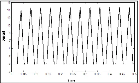
Figure 8: Current waveform of Inductor L1 i.e. IL1 and
[image:4.595.306.550.337.497.2]L2 i.e. IL2
[image:4.595.38.276.343.498.2]Figure 9: Voltage across capacitor C1
Figure 10: Voltage across capacitor C2
4. SUPPLY AND DEMAND CONTROL BY RF
BATTERY
[image:4.595.42.282.582.725.2]© 2017, IRJET | Impact Factor value: 5.181 | ISO 9001:2008 Certified Journal | Page 968
Fig-6: Diagram of redox Flow batteryAmong the secondary batteries such as Li ion battery, NaS battery are very efficient in DC micro grid system. Fluctuation on the output side is smoothened by RF Battery and this battery is also used for detection of state of charge (SOC) during the current flows in the cells. DC-DC converter connects the battery to the Dc bus to control the charge and discharge during demand and supply. Electric power flows from the generator to the DC bus, and flows out to loads. When the electric power flows from generator to the DC bus is larger than the power flows out to the load, the voltage of the bus increases and vice versa. Supply and demand balance of the system can be maintained because the bi-directional DC-DC converter control the voltage of the DC bus at constant by charging, when it is higher than a target, or dis-charging, when it is lower. The battery charges when its voltage at distant point is higher because power generation is greater than power consumption, while voltage is lower during discharge
5. CONCLUSIONS
Micro-DC grid, its characteristics and advantages are re-explained here. In this paper, dual half buck voltage balancer which is used in micro-DC grid and its control strategy are explained. A neutral line is created which is connected earth to balance two output voltages and to protect personnel from any type of hazards. Voltage balancer has ability to overcome the shoot-through problem. Under fluctuating load, unbalanced loads and different input voltage it can balance its output voltage. Storage element like RF battery is explained which maintain supply and demand balance in the system.
REFERENCES
1). Xianjin Zhang And Chunying Gong, Member, IEEE “Dual-Buck Half-Bridge Voltage Balancer” IEEE Transactions on Industrial Electronics, Vol. 60, No. 8, August 2013.
2). Dual-Buck Half-Bridge Voltage Balancer Telugu Siva Sai1 And P. Sai Sampath Kumar, International Journal of Innovative Research in Science & Engineering, ISSN (Online) 2347-3207.
2). H. Kakigano, Y. Miura, T. Ise, and R. Uchida, “DC voltage control of the DC micro-grid for super high quality distribution,” in Proc. IEEE PowerElectronics Specialists Conference, Korea, 2006, pp.518-525.
3). Naoki AyAi*, Toshiya HisAdA, Toshikazu sHibATA,
Hidekazu MiyosHi, Takashi iwAsAki and ken-ichi kiTAyAMA “DC Micro Grid System”.
4). S. V. V. S. K. Reddy1 and Y. Srinivavasa Rao2 “ADVANCED FUZZY LOGIC CONTROL BASED DUAL-BUCKHALF-BRIDGE VOLTAGE BALANCER”, Industrial Science, ISSN: 2347-5420, Volume-1 | Issue-7 | Oct-2014.
5). Sandeep Anand and B. G. Fernandes “Optimum voltage level for DC micro grids” Electrical Engineering Department Indian Institute of Technology Bombay, India, IEEE member.
6). DC MICROGRIDS – A SOLAR “BACK TO THE FUTURE” Sol Haroon, Lead Systems Engineer,