RESEARCH ON MUTUAL COUPLING CORRECTION OF
ARRAY OUTPUT SIGNAL BY BP NETWORK
1, 2BIN PEI, 1HUI HAN, 3YANJUN ZHANG, 2YING SHENG, 2SHIJI YUAN
1 The State Key Laboratory of Complex Electromagnetic Environmental Infects on Electronics &
Information System, China 2 63888 Troop, Jiyuan, China
3
Air Defense Force Academy, China
ABSTRACT
The method of mutual coupling correction of array output signal is studied in the paper. According to array signal processing’s feature, array error model is analyzed and array mutual coupling is studied. The method that smart antennas’ channel calibration by BP network in wireless communication is proposed, which improves the accuracy of algorithms , such as the DOA estimation algorithm, Beam Forming algorithm etc. 8-unit uniform linear array and 8-unit uniform circular array are simulated by computer, and the results are compared with spatial spectrum lines of before-after correction. The proposed method is effective, for computer simulation experimental results are in line with the theoretical ones.
Keywords:BP Network, Array Antenna, Channel Calibration
1. INTRODUCTION
Smart antenna technology combines space division multiplexing (SDM) and frequency division multiplexing (FDM), time division multiplexing (TDM) or code division multiplexing (CDM) [1-4], and thereby makes use of limited frequency band at its maximum. DOA (direction of arrival) estimation is widely used in various fields, such as wireless communication, radar, navigation and sonar super-resolution. Theory and technology of DOA estimation have greatly evolved. Having been research thoroughly for many years, MUSIC (multiple signal classification) Algorithm[5] and ESPRIT algorithm have pioneered a new era of intrinsic structural method, becoming the most classic and commonly-used method. However, most of high-resolution spectral estimation algorithms are based on precisely known array manifold. While in the actual project, due to inevitable errors, a certain degree of deviation and disturbance always emerge in the practical array manifold and many high-solution spectral estimation algorithms will seriously deteriorate even lose efficacy. Therefore, array error is always regarded as a bottleneck where high-solution spatial spectral estimation techniques walk towards practical use.
Early array calibration is achieved directly through discrete measurement, interpolation and storage to array manifold. However, realization of these methods costs too much while with insignificant effects. Thus, after 1990s, people
gradually transform array error calibration into a parameter estimation problem by modeling array disturbance.
As a computing structure, neural network has various superior performances, such as rapid response capability, high-degree robustness and fault-tolerant ability. Therefore, it is widely used in communication [6]. Literature [7] proposes it approximate nonlinear function from array output data to the optimal weight vector by radial basis function network. The literature [8] does a research on multi-beam antenna’s adaptive nulling. Literature [9] [10] propose that the radial basis neural network should be used in the uniform circular array DOA, only take mutual coupling effects into consideration. Meanwhile, it can only be used for DOA estimation, without strong applicability.
ISSN: 1992-8645 www.jatit.org E-ISSN: 1817-3195
2. ARRAY MODELING
For M-unit planar array of arbitrary geometric structure, N (M>N) narrow point source entered in the form of plane wave (wavelength= λ0 ). Its
orientation vector isθ=
[
θ1,θ2,⋅ ⋅⋅,θN]
. The authorselects the first array element as origin of coordinates. The plane where planar array lied is X-Y plane. As we knew from the previous chapters, snapshot vector receive by planar array can be expressed as
( ) ( ) ( )
t A S t N( )
tX = θ,ρ + (1)
X(t) is M×1 dimensional snapshot data vector; N(t) is M×1dimensional array noise vector; S(t) is
1 ×
N dimensional incident signal amplitude vector.
(
) (
)
(
)
[
aθ1,ρ ,aθ2,ρ, ,aθN,ρ]
A= ⋅ ⋅⋅ serve as M×N
dimensional array flow matrix. a
( )
θj,ρ is array-oriented vector corresponding to source j, while ρis array parameters that related to array-oriented vector, such as array element’s amplitude-phase errors, mutual coupling parameters, its positions, etc. When amplitude-phase errors don’t exist in array elements, assuming each element is identical omnidirectional antenna, and array element 1’s complex gain is normalized into 1, array-oriented vector can be expressed
( )
[
j f ( ) j f ( )]
Tj
j M j
e e πτ θ ρ πτ θ ρ
ρ
θ 2 02 , 2 0 ,
, , ,
1 ,
a = ⋅ ⋅⋅
(2)
( )
jT i j
i
cr v 1
,ρ =
θ
τ (3)
[
]
Ti i i
i x y z
~ , ~ , ~
r = (4)
[
]
Tj j j j
j φ θ φ φ
θ cos ,cos cos ,sin
sin
vj= (5)
( )
θ ρτi j, is source j reached to array element i with respect to the delay of the coordinate origin.
i
r
is coordinate vector of element i, andv
j is orientation vector of source j.3. ARRAY ELEMENTS MUTUAL
COUPLING
When constructing model of array-oriented vector, every array element is often hypothesized independently. However, the mutual-coupling effects of array antenna are actually inevitable. When operating at a high switching frequency, effects of Mutual Coupling is more obvious of decreasing array element space to avoid the fuzzy of flow patterns. Because of secondary reflection of
open circuit voltage incident, output voltage of every array element change to open circuit voltage, and the coupling coefficient is simply a linear superposition. In that occasion, the array-oriented vector is carried as
( )
θ,ρ Z( )
θ ,ρa ~
j = a j (6)
Simultaneously, array flow matrix can be expressed as
(
) (
)
(
)
[
]
ZAA= θ ρ θ ρ ⋅ ⋅⋅aθN,ρ =
~ , , , a ~ , , a ~ ~ 2
1 (7)
The effect of mutual coupling can be modeled with direction of array element’s amplitude-phase errors as follows
( )
( )
( ) ( )
[
]
( )
(
θ ρ) ( )
θ ρ ρ θ ρ θ ρ θ ρ θ ρ θ , a , , , a , /a , a , a , a ~ j j j j j j j • = • = = Z W Z Z (8)(
) (
)
(
)
[
]
(
) (
)
(
)
[
wZ wZ wZ]
AA N N • ⋅⋅ ⋅ = ⋅⋅ ⋅ = ρ θ ρ θ ρ θ ρ θ ρ θ ρ θ , , , , , , , , , , a ~ , , , a ~ , , a ~ ~ 2 1 2 1 (9)
Here, amplitude-phase errors matrix
(
) (
)
(
)
[
wZ,θ1,ρ,wZ,θ2,ρ,⋅ ⋅⋅,wZ,θN,ρ]
can beanalyzed by the coupling coefficient with the degree of freedomM2+M
. However, the degree of freedom for amplitude-phase error is reduced obviously because of special structure of mutual coupling matrix. For example, M-unit uniform linear array, the degree of freedom is ρ≤M, while the M-unit uniform circular array is ρ=M/2+1
(M is even) or ρ=M/2+1/2 (M is odd).
Based on above analysis and modeling, the effect of array elements mutual coupling can be modeled with direction of the amplitude-phase error.
4. MUTUAL COUPLING CORRECTION
BASED ON BP NEURAL NETWORK
From the above, the array mutual coupling errors can be modeled by the complex gain error unrelated to the direction. The BP network has global approximation ability, this paper uses BP network to do the channel correction.
Accounting for the simultaneous presence of channel gain and phase inconsistency, and array mutual coupling effect, the actual array output signal vector is
( )
t AS( )
t N( )
tX~ =Γ + (10)
( ) ( )
[
X t X t]
( ) ( )
AR A I ER SS H
H = Γ Γ +σ2
= (11)
The noise subspace, obtained after the eigenvalue decomposition to (11), is not orthogonal with the space conceived by the signal direction matrix. Then using MUSIC spatial spectrum peak can’t accurately estimate signal's DOA, even no expectation of peak number.
In order to make the MUSIC algorithm remain effective, one way is to output signal vector
multiplied by
( )
Γ−1. Then (10) is changed to( )
t AS( ) ( ) ( )
t N tX = + Γ−1 (12)
After this step and then uses the MUSIC algorithm, the signal DOA estimation value can be got. This method, by multiplying a matrix to counteract the model error, we call it matrix compensation method.
To sum up, the matrix compensation method can be viewed as a nonlinear mapping. From the actual output signal vector space to the output vector space after offset error, neural network can be used to solve the mapping. Considering the array output signal distribution is not limited to a particular region, and the BP network is a typical global approximation network, therefore, this paper proposes using BP network to obtain channel calibration.
Figure1: The Calibration System Block Diagram Based On BP Network Channel
As shown in Figure 1, M antennas are consisting of spaced linear antenna array, signal is input to the BP network after preprocessing. The hidden layer
activation function is of S function type. The output layer is linear transfer function.
Preprocessing: considering the follow-up channel calibration, such as DOA estimation or beam forming, we consider the direct use of antenna array output vector as the input of neural network in this paper. But the antenna array output is complex signal, which needs to be separated into the real and imaginary parts, and vector X~′of dimension 2M is get, as the input of neural network. Then the output will also be separated into real and imaginary parts, forming vector of dimension 2M.
This paper considers the use of variable learning rate BP algorithm for training, i.e.
(
)
( )
( )
( )
( )
> +
< + =
+
Σ Σ
Σ Σ
n E n E n k
n E n E n k n
dec inc
) 1 (
) 1 ( 1
η η η
(13)
5. COMPUTER SIMULATION RESULTS
AND DISCUSSION
The proposed method is simulated by computer and the results are discussed in this section.
ISSN: 1992-8645 www.jatit.org E-ISSN: 1817-3195
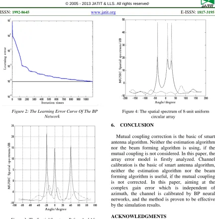
[image:4.612.302.516.69.270.2]Figure 2: The Learning Error Curve Of The BP Network
Figure 3: The Spatial Spectrum Before And After Correction
In order to further investigate the performance of this method, the simulation of 8-unit uniform circular array is carried out.
Aiming at 8-unit uniform circular array which element distance is d=λ/2 was simulated, and the radius is 0.6533λ with the same BP neural network structure of case 1. In the phase of testing, using three independent narrowband far-field signals which direction is -20°, 0°, 40°, and the S/N is 20dB.The solid line is the MUSIC spatial spectrum which is regulated by the proposed method, the dash-dotted line is the original line, and the dotted line is the ideal without channel errors in Figure 4. Similarly, the original spectrum is already useless, and the MUSIC spatial spectrum which is regulated showed 3 distinct spikes, and the peak position is same as the direction of the wave.
Figure 4: The spatial spectrum of 8-unit uniform circular array
6. CONCLUSION
Mutual coupling correction is the basic of smart antenna algorithm. Neither the estimation algorithm nor the beam forming algorithm is using, if the mutual coupling is not considered. In this paper, the array error model is firstly analyzed. Channel calibration is the basic of smart antenna algorithm, neither the estimation algorithm nor the beam forming algorithm is useful, if the mutual coupling is not corrected. In this paper, aiming at the complex gain error which is independent of azimuth, the channel is calibrated by BP neural networks, and the method is proven to be effective by the simulation results.
ACKNOWLEDGMENTS
This work was supported by The State Key Laboratory of Complex Electromagnetic Environmental Infects on Electronics & Information System, China.
REFERENCES:
[1] P. Vandenameele, L. Van Der Perre, M. G. E. Engels, B. Gyselinckx, and H. J. De Man, “A combined OFDM/SDMA approach”, IEEE J. Select, Areas Commun, Vol.18, No.11, 2000, pp. 2312-2321.
[image:4.612.104.286.297.483.2][3] Josef Johannes Blanz, Apostolos Papathanassiou, “Smart antennas for combined DOA and joint channel estimation in time slotted CDMA mobile radio systems with joint Detection”,
IEEE Transactions on Vehicular Technology,
Vol. 49, No. 2, 2000, pp. 293-306.
[4] Weber R, Nossek J A, “Efficient DOA tracking
for TDMA-based SDMA mobile
communications”, Proceeding of the IEEE Vehicular Technology Conference, 1999, pp. 2099-2103.
[5] Schmidt R O, “Multiple Emitter Location and Signal Parameter Estimation”, IEEE Trans. Antennas and Propagate, Vol. 34, No. 3, 1986, pp. 276-280.
[6] S. Fiori, “Blind Signal Processing by the Adaptive Activation Function Neurons”, Neural Networks, Vol. 13, No. 6, 2000, pp. 579-611. [7] Yong Up Lee, Jinho Choi, Iickho Song,
“Distributed Source Modeling and Direction of Arrival Estimation Techniques”, IEEE Transactions Antennas and Propagation, Vol. 45, No. 4, 1997, pp. 960-969.
[8] Yuh-Shane Hwu, Srinath M D, “A Neural Network Approach to Design of Smart Antennas for Wireless Communication Systems”. Signals, Systems&Computers, 1997, Conference Record of the Thirty-First Asilomar Conference on, Vol. 1, No. 2, 1997, pp. 145-148. [9] Badidi L, Radouane L, “A Neural Network Approach for DOA Estimation and Tracking”,
Statistical Signal and Array Processing, 2000, Proceedings of the Tenth IEEE Workshop on, Vol. 14, No. 16, 2000, pp. 434 -438.