International Journal of Emerging Technology and Advanced Engineering
Website: www.ijetae.com (ISSN 2250-2459, ISO 9001:2008 Certified Journal, Volume 5, Issue 2, February 2015)
519
Controlling the Vibration of Bus Suspension System using PID
Controller
Arti Tiwari
1, Mohd. Khursheed Siddique
2, Mohd. Naseem
31,2,3Department of Electrical Engineering, Integral University
Abstract—The purpose of vehicle suspension system is to improve ride comfort and road handling. This paper presents the application of P controller, PI controller and PID controller to control the vibration of bus suspension system. 1/4th model of bus suspension system is used to simplify the problem.
A open loop response of bus suspension system is developed by using equations of 1/4th model of bus suspension system by using the Matlab/Simulink. The response of open loop bus suspension system is obtained by using equation and state space model. For controlling the bus suspension use the feedback controller. In this paper P controller, PI controller and PID controller are used to control the vibration to give the smooth response of bus suspension system.
Keywords—Bus suspension system, dynamic modelling, P controller, PI controller, PID controller, State space model, Matlab/Simulink.
I. INTRODUCTION
Nowadays, there is a great problem providing the bus suspension system with high speed & smooth drive from olden days, large control method has been proposed to overcome these suspension problem. Many active suspension control approaches such as linear Quadratic Gaussian (LQG) control, adaptive control & nonlinear control are developed and proposed so as to manage the problem. In this paper P, PI, & PID controllerare used to control the bus suspension system. The values of Kp, Kd and Ki are calculated using Ziegler-Nicholas method. State space theory will be used in order to create the mathematical modelling of the system. The simulation is using the Matlab/Simulink software.
II. BUS SUSPENSION SYSTEM
The bus suspension system is one of the impressive challenging problems in terms of controlling the system. The control objective of this system is to give the smoothest riding for who is on the bus. There are three system for suspension system which are active, semi active and passive suspension system.
From the bus suspension system model, the dynamic equation is obtained by using the Newton’s law. Then, this dynamic equation will be transfer into the Matlab to get the transfer function using the built in function.
[image:1.612.325.562.307.449.2]In this paper 1/4th model of the bus is used to design a simple bus suspension system . The model of bus suspension system is shown below -
Figure 1 : Bus suspension system model of 1/4th bus
Where the constraints and variables are-
System Parameters
M1= 250 kg, 1/4 bus body mass M2=320 kg, Suspension mass
K1= 80,000N/m, spring constant of suspension system K2= 500,000N/m, spring constant of wheel and tire b1= 350Ns/m, Damping constant of suspension system b2=15,020Ns/damping constant of wheel and tire U= Control force
The dynamic equation can be obtained as the following-
International Journal of Emerging Technology and Advanced Engineering
Website: www.ijetae.com (ISSN 2250-2459, ISO 9001:2008 Certified Journal, Volume 5, Issue 2, February 2015)
520
Simulink model of Bus suspension system –a1 v1 x1
a2 v2 x2
w u
sum5 sum4
sum3
sum2 sum
-K-spring 2
-K-spring 1
netsum1
-K-mass 2
-K-mass 1
-K-damper2
Scope
1 s Integrator3 1 s Integrator2
1 s Integrator1 1
s Integrator
du/dt
Derivative
[image:2.612.328.561.154.311.2]
-K-Damper 1
Figure 2 : Simulink model of bus suspension system
[image:2.612.51.291.158.389.2]Simulation output -
Figure 3 : Simulation output of bus suspension system
State space model -
Figure 4 : Open loop step response of bus suspension system
We want to design a feedback controller so that when the road disturbance (W) is simulated by a unit step input, the output (X1-X2) has a settling time less than 5 seconds and an overshoot less than 5%. For example, when the bus runs onto a 10 cm high step, the bus body will oscillate within a range of +/- 5 mm and will stop oscillating within 5 seconds.
From the picture above and Newton's law, we can obtain the dynamic equations as the following:
[image:2.612.50.287.416.612.2]International Journal of Emerging Technology and Advanced Engineering
Website: www.ijetae.com (ISSN 2250-2459, ISO 9001:2008 Certified Journal, Volume 5, Issue 2, February 2015)
[image:3.612.328.560.152.245.2]521
Simulink model using state space model –Figure 5 : State space model of bus suspension system
[image:3.612.75.256.188.261.2]Simulink output-
Figure 6 : Simulink output of state space model of bus suspension system
III. CONTROLLER
A controller is a device, may be in the form of analogue circuit, chip or computer that monitors and physically alters the operating conditions of a given dynamical system. From the past decades, the importance of the control system has been increased due to the increment in complexity of the system under control and to achieve optimum performance of the system
.
[image:3.612.48.292.310.516.2]Table – 1
Response of proportional , integral and derivative controller [1]
P controller -
P controller is mostly used in first order processes with single energy storage to stabilize the unstable process. The main usage of the P controller is to decrease the steady state error ofthe system. As the proportional gain factor K increases, the steady state error of the system decreases
Simulink model of P controller with bus suspension system -
Figure 7 : Simulink model of bus suspension system using P controller
Simulink output –
[image:3.612.326.560.356.422.2] [image:3.612.324.565.463.683.2]International Journal of Emerging Technology and Advanced Engineering
Website: www.ijetae.com (ISSN 2250-2459, ISO 9001:2008 Certified Journal, Volume 5, Issue 2, February 2015)
522
PI controller- [image:4.612.329.562.190.304.2]P-I controller is mainly used to eliminate the steady state error resulting from P controller. However, in terms of the speed of the response and overall stability of the system, it has a negative impact. This controller is mostly used in areas where speed of the system is not an issue.
Figure 9 : Simulink model of bus suspension system using PI controller
Simulink output-
Figure 10 : Simulink output of bus suspension system using PI controller
PID controller-
The PID controller calculation involves three separate parameters, and is accordingly sometimes called three-term control: the proportional, the integral and derivative values, denoted P, I, and D. The proportional value determines the reaction to the current error, the integral value determines the reaction based on the sum of recent errors, and the derivative value determines the reaction based on the rate at which the error has been changing.
[image:4.612.47.292.342.561.2]Simulink model of PID controller with bus suspension system -
Figure 11 : Simulink model of bus suspension system using PID controller
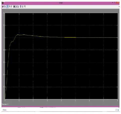
Simulink output –
Figure 12 : Simulink output of bus suspension system using PID controller
IV. CONCLUSION
[image:4.612.322.563.357.584.2]International Journal of Emerging Technology and Advanced Engineering
Website: www.ijetae.com (ISSN 2250-2459, ISO 9001:2008 Certified Journal, Volume 5, Issue 2, February 2015)
523
REFERENCES
[1] A. Karthikraja, G. Petchinathan, S. Ramesh, Stochastic Algorithm for PID Tuning of Bus Suspension System, IEEE Proc. INCACEC 2009.
[2] Abdolvahab Agharkakli, Chavan U. S. Dr. Phvithran S,―Simulation And Analysis Of Passive And Active Suspension System Using Quarter Car Model For Non Uniform Road Profile‖ Research and Applications (IJERA) ISSNVol. 2, Issue 5, September- October 2012, pp.900-906
[3] Senthil kumar, S.Vijayarangan,‖Analytical and experimental studies on active suspension system of light passenger vehicle to improve ride comfort‖ ISSN 1392 - 1207. MECHANIKA. 2007. Nr.3 [4] A. Karthikraja, G.Petchinathan and S.Ramesh,― PID Based Bus
Suspension System Control Using Evolutionary Algorithms‖ International Journal of Advanced Engineering Applications, Vol.4, Iss.2, pp.60-68 (2011)
[5] T. Ram Mohan Rao, G.Venkata Rao, K. Sreenivasa Rao & A. Purushottam,―Analysis of Passive and Semiactive Controlled Suspension Systems for Ride Comfort in an Omnibus Passing Over a Speed Bump‖ IJRRAS 5, October 2010
[6] Andronic Florin, Manolache-Rusu Ioan-Cozmin, Pătuleanu Liliana,―Passive Suspension Modeling using Matlab, Quarter Car Model, Input Signal Step Type‖ Tehnomus- New Technologies and Products in Machine Manufacturing Technologies 258.


![Table – 1 Response of proportional , integral and derivative controller [1]](https://thumb-us.123doks.com/thumbv2/123dok_us/8704193.880283/3.612.324.565.463.683/table-response-proportional-integral-derivative-controller.webp)