Technology (IJRASET)
©IJRASET 2015: All Rights are Reserved
289
Bidirectional DC-DC Converter with MPPT
Controller Using PV Array
D. Buvana1, R. Jayashree2
1
Asst. Professor / EEE, Sri Krishna Engineering College, Chennai – 601 301 2
Prof. / EEE, B. S. Abdur Rahman University, Chennai – 600 048
Abstract - This paper proposes simulation of Bidirectional DC - DC converter with Maximum Power Point Tracking using Photo Voltaic cell with motor load in boost and buck mode respectively. The proposed two level converters have the advantages of transformer less operation. This converter can operate with steep conversion ratio, soft- switching, continuous inductor current and fixed switching frequency. In the proposed DC-DC converter topology, the switched coupled-inductor is used instead of coupled inductor. The proposed converter is carried out in MATLAB working platform and the output performance is analyzed. It shows that Bidirectional DC - DC converter with Maximum Power Point Tracking using Photo Voltaic cell gives more efficiency.
Keywords: Maximum Power Point Tracking, Photo Voltaic,Perturb and Observe.
I. INTRODUCTION
The market for residential photovoltaic (PV) converter is becoming highly competitive. PV manufacturers are competing to increase the efficiency for every 0.1%. From the Maximum Power Point Tracking (MPPT) algorithm point of view, the existing methods, such as Perturbation and Observation (P&O) and incremental conductance (IncCond), can track the maximum power point properly and the dynamic response is good enough to deal with changes in temperature and irradiation. The topology used in [1] raises the efficiency for the DC/DC converter of the PV Power Conditioning System (PVPCS), and it minimizes switching losses by adopting a resonant soft-switching method. Inverter technologies for connecting photovoltaic (PV) modules to a single-phase grid is given in [2]. P&O is simple to implement and thus can be implemented quickly. The concept behind the "Perturb and Observe" (P&O) method is shown in Fig.1 to modify the operating voltage or current of the photovoltaic panel until you obtain maximum power from it is in [3]-[5].
Fig.1 Perturb and Observe algorithm
©IJRASET 2015: All Rights are Reserved
290
In this paper, a three-port bidirectional DC-DC converter is given for grid-interactive Photovoltaic (PV) system application. The three-phase topology is suitable for residential power requirement. The control of battery and PV are naturally decoupled. The maximum power of the PV cell is tracked with an adjusted P&O MPPT algorithm based on Boost DC/DC converter. A DC/AC inverter has been used to connect the PV cell to the grid and regulate the output voltage of DC/DC converter. The given model can work under sudden change of environment temperature or solar.MPPT method is able to considerably increase the efficiency of the PV system during rapidly changing irradiance is given in [10] & [11].
The DC-DC converter is used for boosting a low voltage of the PV array up to the high dc bus voltage, which is not less than grid voltage level is given in [12]. The Perturb and Observe (P&O) method operates by periodically perturbing (i.e. incrementing or decrementing) the array terminal voltage or current and comparing the PV output power with that of the previous perturbation cycle. The proposed Perturb and Observe control algorithm is a software program with a self-tuning function which adjusts the array reference voltage and step size of the voltage to achieve maximum power point. When the external environment changes suddenly the system can track the maximum power point quickly. Both buck and buck-boost converters have succeeded to track the MPP due the use of P&O technique [13].
A Thermo Electric Generator (TEG) is a low voltage, high current DC power source with a linear V-I characteristic. The linear V-I characteristic produces a P-I characteristic with a flatter peak relative to other sources. This can result in large operating point variations while performing Maximum Power Point Tracking (MPPT). A novel high step-up DC/DC converter topology operating with a fractional short-circuit MPPT algorithm is given in [14].
Bidirectional DC-DC converter with MPPT controller and motor load is proposed. This topology has less components than other topology and it also improves the voltage conversion ratio of the circuit and its performance. The two level cascaded circuit which operates on both boost and buck mode is explained in section.2. The proposed circuit is implemented in the MATLAB platform is given in section.3.
II. TWOLEVELBIDIRECTIONALDC-DCCONVERTER
Fig.1 shows the proposed two level non isolated dc-dc converter with inductor current control. In the bidirectional circuit, while the current flowing through the positive terminal of L1 inductor is considered as positive. Similarly the current flowing through the positive terminal of L2 inductor is considered to be positive. The current flows through the switchesT11 andT12are positive, while
the current flows through their respective switches to drain. The current flows through the Ta switch is positive, if it is flowing
from the source to drain. The current flowing into the positive terminal of the capacitors
C1,C 2
are considered to be positive and the drain-source voltage is considered to be positive for all the switches. The diodes D1 are added to the proposed cascadingcircuit, which allows the current in one direction. The capacitors and the diodes are used for improving the performance of the converter. The modes of operation of the proposed circuit for both the modes like buck and boost operation is given in the next section A.
A. Motoring And Regenerative Modes Of Operation
In boost mode of operation switch T11is acting as a main power switch and the T12acting as the freewheeling diode, similarly for the
buck mode of operation switch, T12acting as the main switch and the T11acting as the freewheeling diode. The proposed cascaded
topology gives an enhanced performance for the converter which have series connection of the capacitors and the diode. The addition of the switched coupled inductor provides the high conversion ratio. From fig.2 the overall output voltage in boost mode is given by,
Technology (IJRASET)
[image:4.612.116.507.93.203.2]©IJRASET 2015: All Rights are Reserved
291
Fig. 2 Two level non isolated dc-dc converter with inductor current control
where,
1 2
N N
N turns ratio for boost mode, for this mode 2
N windings must be greater thanN1windings, Viis the input voltage,
m
L is the mutual inductorsm 1,2, Cm is the capacitors, m 1,2... n ,
k
is the Boltzmann constant,m
T absolute temperature
of the P-N junctionm 1,2... n ,
q
is the magnitude of charge on electron,1
D
is the duty ratio of the switch T11. Similarly forthe buck mode operation over all voltage is given in equation (2).
)
2
(
1
)
(
1
*
1
1 2 1 2 1D
nV
V
q
kT
dt
t
i
C
dt
di
L
K
T
T
V
V
high lown m m n m m m m off on i buck
where, 1 2 N NK turns ratio for boost mode, for this mode 2
N windings must be less thanN1windings, Vhigh is the high voltage side.
III.SIMULATIONCIRCUIT&RESULTS
A. Discrete DC Machine
1) Boost Mode: Motor Parameters: Armature parameter:Ra=0.78 Ω, La=0.016 H, Rf=50 Ω, Field parameter: Lf=26 H, Inductance between armature and field: Laf=1.234 H, Total inertia: J=0.05 kg.m^2, Viscous friction coefficient: Bm=0.01 N.m.s, Voltage : Vin=18 , Vout=42 V, Io=1.8 A .
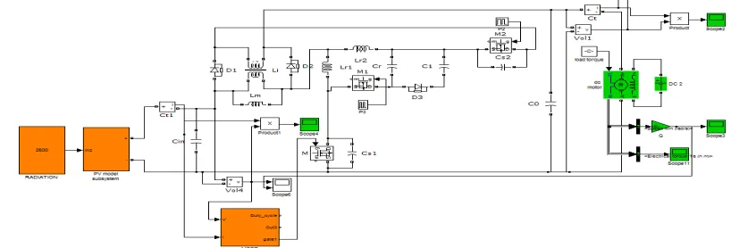
The simulation of proposed two stage non isolated bidirectional DC-DC converter with MPPT controller is done using MATLAB and results are presented. Fig.3(a) shows the converter with controller circuit in boost mode. The photo voltaic power is given as input to converter with Maximum Power Point controller. The controller decides duty cycle of converter with P&O algorithm. The output of two level non isolated bidirectional DC-DC converter is given to DC motor. Fig.3 (b) shows solar input voltage as 18 V. Fig.3(c) shows output voltage as 42 V. Fig.3(d) shows the armature speed of 510 rpm. Fig.3(e) shows the motor torque. Fig.3(f) shows the ZVS operation of main switch. Fig.3(g) shows the output power of DC-DC converter without and with MPPT controller for different input voltage. Fig.3(h) shows the efficiency comparison between with and without MPPT controller of proposed system.
[image:4.612.103.512.562.701.2]©IJRASET 2015: All Rights are Reserved
292
Fig.3(b) Solar input Voltage Fig.3(c) Output voltage
Fig.3(d) Armature speed Fig.3(e) Motor Torque
Fig.3(f) ZVS operation across switch Fig.3(g) Efficiency comparison
Input voltage (V) Output power (w)
Output power with MPPT(w)
Boost normal
efficiency Efficiency
14 49.5 50 82.5 92.5
18 71 76.3 83 93.2
22 95.3 100.3 83.5 93.3
26 122.7 127.4 83.6 93.6
Fig.3(h) Output power without and with MPPT
2) Buck Mode
Technology (IJRASET)
©IJRASET 2015: All Rights are Reserved
293
and field: Laf=1.234 H, Total inertia:J=0.05 kg.m^2, Viscous friction coefficient: Bm=0.01 N.m.s, Voltage: Vin=42 V , Vout=18 V, Io=1.5 A .
Fig.3(i) shows the converter with controller circuit in buck mode. The photo voltaic power is given as input to converter with Maximum Power Point controller. The controller decides duty cycle of converter with P&O algorithm. The output of two level non isolated bidirectional DC-DC converter is given to DC motor.
Fig.3(j) shows Solar input voltage as 42 V. Fig.3(k) shows the output voltage as 18 V. Fig.3(l) shows the armature speed as 250 rpm. Fig.3(m) shows the motor torque. Fig.3(n) shows ZVS across switch. Fig.3(o) shows the output power of DC-DC converter without and with MPPT controller and Fig.3(p) efficiency comparison between without and with MPPT controller. It shows that by the use of MPPT controller more efficiency is achieved.
Fig.3(i) DC/DC Converter with MPPT controller in buck mode
©IJRASET 2015: All Rights are Reserved
294
Fig.3(l) Armature speed Fig.3(m) Motor Torque
Fig.3(n) ZVS operation across main switch Fig.3(o)Efficiency with and without MPPT controllers
Input voltage(V) Output power(w)
Output power with MPPT (w)
Buck normal Efficiency
Buck MPPT Efficiency
38 26 27.7 79.5 79.8
42 29.5 31.8 79.7 80.5
46 33.2 35.5 79.8 80.6
50 37.1 40 79.9 81.6
Fig.3(p) Output Power without and with MPPT
IV.CONCLUSION
This paper proposes simulation of Bidirectional DC - DC converter with Maximum Power Point Tracking using Photo Voltaic cell with motor load in boost and buck mode respectively. The proposed two level converter has the advantages of transformer less operation. This converter can operate with steep conversion ratio, soft- switching, continuous inductor current and fixed switching frequency. In the proposed DC-DC converter topology, the switched coupled-inductor is used instead of coupled inductor. The proposed converter is carried out in MATLAB working platform and the output performance is analyzed. It shows that Bidirectional DC - DC converter with Maximum Power Point Tracking using Photo Voltaic cell gives more efficiency.
REFERENCES
[1] M. Bhatnagar and B. J. Baliga, “Comparison of 6 H-SiC, 3 C-SiC, and Si for power devices,” IEEE Trans. Electron Devices, vol. 40, no. 3, pp. 645–655, Mar. 1993.
©IJRASET 2015: All Rights are Reserved
295
[3] Y.-H. Ji, D.-Y. Jung, J.-G. Kim, J.-H. Kim, T.-W. Lee, and C.-Y. Won, “A real maximum power point tracking method for mismatching compensation in PVarray under partially shaded conditions,” IEEE Trans. Power Electron., vol. 26, no. 4, pp. 1001–1009, Apr. 2011.
[4] A. K. Abdelsalam, A. M. Massoud, S. Ahmed, and P. N. Enjeti, “High-performance adaptive perturb and observe MPPT technique for photovoltaic-based microgrids,” IEEE Trans. Power Electron., vol. 26, no. 4, pp. 1010–1021, Apr. 2011.
[5] Q. Li and P. Wolfs, “A review of the single phase photovoltaic module integrated converter topologies with three different DC link configurations,” IEEE Trans. Power Electron., vol. 23, no. 3, pp. 1320–1333, May 2008.
[6] Kaithamalai Udhayakumar, Ponnusamy Lakshmi, Kandasamy Boobal,”Hybrid Posicast Controller For A DC-DC Buck Converter” SERBIAN JOURNAL OF ELECTRICAL ENGINEERING Vol. 5, No. 1, May 2008, pp. 121-138.
[7] W. C. So, C. K. Tse and Y. S. Lee,” A Fuzzy Controller for DC-DC Converters”, 1994 IEEE, pp.315-320.
[8] D. Buvana, R. Jayashree, “ An Enhanced Cascaded Topology of non isolated bidirectional DC-DC converter with switched coupled inductor”, International review on modelling and simulations (I.RE.MO.S), Vol.6, N.5, ISSN 1974-9821, Oct 2013, pp. 1371-1382.
[9] Zhan Wang, Hui Li, “Integrated MPPT and Bidirectional Battery Charger for PV Application Using One Multiphase Interleaved Three-port DC-DC Converter” ieee, pp.295-300.
[10] Jingzhe Song, “Simulation of Grid-Connected Photovoltaic System”, IEEE 2008.
[11] R. Prakash, B. Meenakshipriya, R. Kumaravelan, “Modeling and Design of MPPT Controller Using Stepped P&O Algorithm in Solar Photovoltaic System”, World Academy of Science, Engineering and Technology IJEESE Vol:8 No:3, 2014.
[12] T. Chaitanya Ch.Saibabu, J.Surya Kumari, “Modeling and Simulation of PV Array and its Performance Enhancement Using MPPT (P&O) Technique”, .Chaitanya et al, IJCSCN,Vol 1(1),September-October 2011.
[13] Ahmed M. Atallah, almoataz y. Abdelaziz, and raihan s. Jumaah, “Implementation of perturb and Observe mppt of pv system with direct Control method using buck and buck boost Converters”, An international journal (eeiej), vol. 1, no. 1, february 2014.
[14] Ian Laird and Dylan D.C. Lu, “High Step-up DC/DC Topology and MPPT Algorithm for use with a Thermoelectric Generator”, IEEE Transactions on Power Electronics, Vol. 28, No. 7, pp. 3147-3157, July 2013.
ABOUT AUTHOR
D. Buvana has done B.E / EEE in the year 2002 and M.E / PED in the year 2006. She has seven years of teaching and 2 years of industrial experience. She is pursuing her research in the area of DC to DC converters. Currently, she is a working as a Assistant Professor at the Faculty of Electrical and Electronics Engineering in Sri Krishna Engineering College, Anna University, Chennai.