www.ijraset.com Volume 4 Issue IV, April 2016 IC Value: 13.98 ISSN: 2321-9653
International Journal for Research in Applied Science & Engineering
Technology (IJRASET)
©IJRASET: All Rights are Reserved
109
Trespass Prevention System Using IOT
Arun prakash1, Aravind Krishnan2, Dhanabalan3, Anil Kumar4, B Thyla5
1,2,3,4
UG Students , 5 Assistant Professor , Department of ECE, KCG College of technology, Chennai.
Abstract--Trespass Panic System uses an Arduino microcontroller and interfaced with GSM module, an input keypad, sensor and camera. When the password entered does not match with the original, the inbuilt camera is turned ON to capture an image and call is received by the owner through the GSM module. If the password matches with original, owner is intimated by sending a notification through the GSM and the inbuilt camera is turned ON to capture an image. In case of override or destruction of system an alarm is turned on and then a camera is turned ON and the image is stored in SD card module and a phone call will be made to the owner as an emergency notification.
Keywords-- Arduino Uno microcontroller, GSM module, Pressure sensor, LCD display Camera and SD card module, keypad
I. INTRODUCTION
The Arduino microcontroller based digital lock is an access control system that identifies any unauthorized access to any restricted division. The major components include a Micro controller keypad, EEPROM, Camera, sensor, LCD display, GSM and the Servo motor. The system is fully controlled by the ATMEGA328/168 8 bit AVR microcontroller which has a 32Kb for flash memory (5Kb used for the boot loader). The system receives the input from the 4 x 3 matrix keypad attached to it. On receiving the valid password from the user the status is displayed on LCD as “Password is correct” and allows the user to enter the premises. Suppose if password is invalid, “Password Invalid” is displayed on the LCD and camera attached in the front gate will take a picture of the entry and store it in the memory card. Following this a notification message will be sent to the owner about the entry. This way any unauthorized access (including hackers, unknown users) to the premises will be identified.
Suppose if any one tries to override or destruct the setup “Access denied” is displayed on the LCD, an alarm connected to the microcontroller will be turned on and a photo of the miscreants will be captured by an inbuilt camera. Any breakages into the system will be notified through Call to the owner and other authorized channel which are included in the system. In the above process all signals are transferred using IOT.
II. PROPOSED SYSTEM
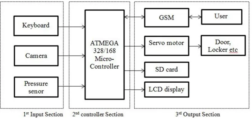
General block diagram of the proposed “microcontroller based security system” has been shown in Figure 1 .It consists of three sections. Those are input, controller and output sections. Initially the controller section remains at waiting state for receiving a signal from input section which includes 4 * 3 Keypad, and Pressure sensors. A keypad has been interfaced with microcontroller to lock or unlock the door this system controls. An LCD display has been used for to display status of the system.Pressure sensors have been placed at door to protect the system.
If anyone tries to unlock the system without authority, then the sensors will be activated and controller will receive a suitable pulse. According to the pulse of input devices, the controller section takes a decision and activates the output section which includes Camera, GSM Module, Servo Motor, and Buzzer.The activation of output device depends on the activity of input section that indicates user unlocks the system with or without authorization. For the authoritative way, controller sends a pulse signal to the servo motor that is also connected with a magnetic switch placed at the door. After 90 degree rotation of servo motor it activates the magnetic switch which is used to lock or unlock the system. At the same time depending on the activity at the door, the owner receives a Call and the image is captured and stored in a SD card module. If anyone tries to break the system, then sensors will be activated and controller receives a pulse and an alarm will be turned ON and camera captures the image following which a notification is sent to the owner and other authorized channel.
©IJRASET: All Rights are Reserved
110
Figure 1.Proposed system
III. METHODOLOGY
The operation of this system is based upon three cases
When a person enters the password using 4*3 keypad the microcontroller checks whether the password is correct or not.
Case 1: If the password is correct, “Password Correct” is displayed on LCD, access is granted for the person and a notification is sent regarding the successful entry. The camera present inside, focussing on the door captures the image of the person who has entered
Case 2: If the password is incorrect the, “Password invalid” is displayed on LCD, the image of the person is captured using a OV7670 camera outside the room and a notification call is received by owner. This also gives a warning signal by emitting a buzzer Sound.
Case 3: In case the person tries to break the system the sequence of events occurs. The events start with an alarm being turned on followed by capturing the image by the OV7670 camera placed outside the room. This is followed by intimation through a call to the owner.
The general facts regarding the three cases are
The notifications are sent by GSM module through Short Messaging Service
The images taken by the camera are stored in the SD card module connected to the microcontroller(ATMEGA328/168) unit
IV. HARDWARE DESIGN
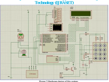
The practical circuit has been designed using Proteus Software as shown in Figure 2. In this circuit diagram microcontrollers are the main components which are used for controlling other devices (GSM Module, 4*3 Keypad, Servo motor, OV7670 camera, LCD, SD card module, sensor and Buzzer).Among the controlling devices camera is used to capture the image which are stored in a SD card module, LCD is used to display status and GSM module is used to initiate a phone call to the owner. The input will be obtained from keypad and assessed by microcontroller, on receiving signal from controller the servo motor is activated
www.ijraset.com Volume 4 Issue IV, April 2016 IC Value: 13.98 ISSN: 2321-9653
International Journal for Research in Applied Science & Engineering
Technology (IJRASET)
[image:4.612.80.535.56.400.2]©IJRASET: All Rights are Reserved
111
Figure 2 Hardware design of this system
V. SOFTWARE DESIGN
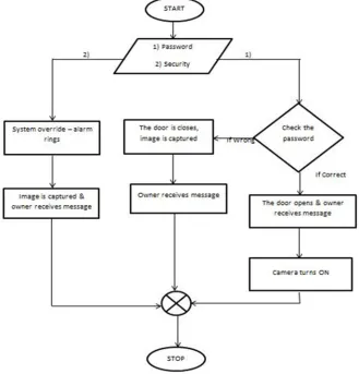
The program flow chart of the proposed home security system has been shown in Figurewhich explains the whole software design procedures. Arduino software is used as a compiler for the designing the program in C language. The instructions given in the program are executed sequentially according to the flow chart. At first, the program initializes all peripheral devices (GSM module, LCD display, Keypad, Sensor, Camera, Servo motor, and Buzzer). This is the precondition for interfacing between microcontroller and peripheral devices. Figure 3 represents the sequence of events taking place in the proposed home security system.
Start
The system has two methods to ensure security: password and sensing security breach
Microcontroller checks the entered password with the original.
If it is wrong the Door will be closed and an image will be captured by camera and the status will be intimated to the owner through a phone call.
If it correct the Door will be opened and the image will be captured by a camera inside the room and the owner receives a Call regarding the status through the GSM module
If the person tries to override or break the system, the alarm will be turned on and an image is taken by the camera which is attached to front of the door and owner is intimated by a call using GSM module.
©IJRASET: All Rights are Reserved
112
Figure 3 software design of this system
VI. RESULTS
Through this paper we have presented the design and implementation of a smart security system based on microcontroller along with GSM for user friendly application.
The system is
Cost effective Easy to handle Less overhead
REFERENCES
[1] Raqibull Hasan, Mohammad M Khan, Asaduzzaman Ashek, I J Rumpa (2015)Microcontroller Based Home Security System with GSM Technology. Open Journal of Safety Science and Technology, 2015, 5, 55-62, Published Online June 2015 in SciRes.
http://www.scirp.org/journal/ojsst,http://dx.doi.org/10.4236/ojsst.2015.52007
[2] Arpita Mishra, Siddharth Sharma, Sachin Dubey, S.K.Dubey (2014) Password Based Security Lock System. International Journal of Advanced Technology in Engineering and Science Volume No.02, Issue No. 05, May 2014
[3] Rana, G.M.S.M., Khan, A.A.M., Hoque, M.N. and Mitul, A.F. (2013) Design and Implementation of a GSM Based Remote Home Security and Appliance Control System. Proceedings of the 2nd International Conference on Advances in Electrical Engineering, Dhaka, 19-21 December 2013, 291-295.
[4] Anil, Anudeep Reddy, Bhanu Chander, Saatwik, Sai Kishore Digital Security System using 8051 microcontroller
Books and Author
[1] C language (E.BALAGURUSAMY)
www.ijraset.com Volume 4 Issue IV, April 2016 IC Value: 13.98 ISSN: 2321-9653
International Journal for Research in Applied Science & Engineering
Technology (IJRASET)
©IJRASET: All Rights are Reserved
113
Websites
[1] https://www.arduino.cc/
[2] https://z4ziggy.wordpress.com/2014/06/13/arduino-keypad-with-1-analog-pin/