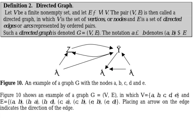
2000-007
MRTC Report 00/24
Applying Configuration Management
Techniques to Component-Based
Systems
Applying Configuration Management Techniques to
Component-Based Systems
BY
MAGNUS LARSSON December 2000
DEPARTMENT OF COMPUTER SYSTEMS INFORMATION TECHNOLOGY
UPPSALA UNIVERSITY UPPSALA
SWEDEN
Dissertation for the degree of Licentiate of Philosophy in Computer Systems at Uppsala University 2000
Applying Configuration Management Techniques to Component-Based Systems
Magnus Larsson
Department of Computer Engineering Mälardalen University Box 883 SE-721 23 Västerås Sweden http://www.idt.mdh.se/ Magnus Larsson 2000 ISSN 1404-5117
To
Christina
ABSTRACT
Building software from components, rather than writing the code from scratch has several advantages, including reduced time to market and more efficient resource usage. However, component based development without consideration of all the risks and limitations involved may give unpredictable results, such as the failure of a system when a component is used in an environment for which it was not originally designed.
One of the basic problems when developing component-based systems is that it is difficult to keep track of components and their interrelationships. This is particularly problematic when upgrading components. One way to maintain control over upgrades is to use component identification and dependency analysis. These are well known techniques for managing system configurations during development, but are rarely applied in managing run-time dependencies. The main contribution of this thesis is to show how Configuration Management (CM) principles and methods can be applied to component-based systems. This thesis presents a method for analysing dependencies between components. The method predicts the influence of a component update by identifying the components in a system and constructing a graph describing their dependencies. Knowledge of the possible influences of an update is important, since it can be used to limit the scope of testing and be a basis for evaluating the potential damage of the update. The dependency graphs can also be used to facilitate maintenance by identifying differences between configurations, e.g., making it possible to recognise any deviations from a functioning reference configuration.
For evaluation of the method, a prototype tool which explores dependencies and stores them under version control has been developed. The prototype has been used for partial analysis of the Windows 2000 platform. Preliminary experiments indicate that most components have only a few dependencies. The method has thus given an indication that the analysis of the effects of component updates may not be as difficult as might be expected.
© Magnus Larsson
Distributed by Department of Computer Engineering, Mälardalen University, Box 883, S-721 23 Västerås, Sweden, and Department of Computer Systems, Information Technology, Uppsala University, Box 325, S-751 05 Uppsala, Sweden
ACKNOWLEDGEMENTS
The research presented in this thesis was carried out within the STINA (Standard Technologies in Industrial Applications) project, which is a cooperation project between Mälardalen University and ABB Corporation.
I sincerely thank my supervisor Prof. Hans Hansson for great support and feedback in response to my ideas.
This work could not have been done without the valuable and important encouragement I have received from my tutor and friend Dr. Ivica Crnkovic. I really appreciate Ivica’s efforts in motivating me to prepare this thesis.
This work has been financed by ABB Automation Products through Erik Danielsson. I wish to thank specially Erik Danielsson for giving me this opportunity.
Also thanks to Frank Lüders, Rolf Sundberg and Christina Larsson for criticizing and reviewing this thesis in a constructive way. Without their valuable input this work may not have been completed.
I especially thank Victor Miller for helping me with the English language.
Special credit is due to Peter Ekman for assisting me with the layout of the document.
Thanks to Erik Gyllenswärd for being a good example and for his encouragement during many years as a colleague at ABB.
Magnus Larsson
LIST OF PUBLISHED ARTICLES
The following articles have been published at international conferences and workshops. These four articles are included in this thesis:
• Development Experiences of a Component-based System
In proceedings 7th Annual IEEE International Conference and Workshop on the Engineering of
Computer Based Systems Edinburgh, Scotland, April 2000. IEEE Computer Society
Authors: Magnus Larsson, Ivica Crnkovic
• Component Configuration Management for Frameworks
In proceeding, Asia-Pacific Software Engineering Conference, Workshop on Software Architecture
and Components Takamatsu, Japan, December 1999.
Authors: Ivica Crnkovic, Magnus Larsson, and Kung-Kiu Lau
• Component Configuration Management
In proceedings ECOOP Conference, Workshop on Component Oriented Programming Nice, France, June 2000.
Authors: Magnus Larsson, Ivica Crnkovic
• New Challenges for Configuration Management
In proceeding, System Configuration Management, SCM-9, proceedings Toulouse, France, September 1999. Lecture Notes in Computer Science 1675, Springer Verlag. Authors: Magnus Larsson, Ivica Crnkovic
Other articles published by Magnus Larsson:
• Software Process Measurements using Software Configuration Management In proceedings The 11th European Software Control and Metrics Conference Munich, Germany, May 2000.
Authors: Ivica Crnkovic, Magnus Larsson, and Frank Lüders
• The Different Aspects of Component Based Software Engineering In proceedings MIPRO (Microprocessor systems, Process control and Information Systems)
Conference Opatija, Croatia, May 2000.
Authors: Ivica Crnkovic, Magnus Larsson, and Frank Lüders
• Object-Oriented Design Frameworks: Formal Specification and Some Implementation Issues
In proceedings 4th IEEE international Baltic workshop on Databases and Information Systems, Vilnius, Lithuania, January 2000.
• A Case Study: Demands on Component-based Development
In Proceedings, 22nd International Conference of Software Engineering Limerick, Ireland, January 2000. ACM, IEEE, SigSoft
Authors: Ivica Crnkovic, Magnus Larsson
• State of the Practice: Component-based Software Engineering Course
In Proceedings, Workshop ICSE 2000 conference, 3rd International Workshop on CBSE, January 2000.
Authors: Ivica Crnkovic, Magnus Larsson, and Frank Lüders
• Processing Requirements by Software Configuration Management
In Euromicro 99, proceedings of the 25th EUROMICRO conference Milan, Italy, September 1999. IEEE, Computer society
Authors: Ivica Crnkovic, Peter Funk, and Magnus Larsson
• Managing Standard Components in Large Software Systems
In Proceedings on 2nd workshop on Component Based Software Engineering Los Angeles, USA, May 1999.
CONTENTS
THESIS 11 1 Introduction 11 1.1 Method 1.2 Related work 1.3 Contribution2 Component-Based Software Engineering 16
2.1 Component Definitions 2.2 Component Models 2.3 Patterns
2.4 Interfaces
2.5 Commercial Off-The-Shelf Components 2.6 Component-based Development 2.7 Development Cycle 3 Configuration Management 32 3.1 Version Management 3.2 Change Management 3.3 Build Management 3.4 Release Management 3.5 Workspace Management 3.6 Related Work 4 Dynamic Configurations 36
5 Component Configuration Management 38
5.1 Component Identification 5.2 Configuration Model 5.3 Change Management 5.4 Managing Dependencies
5.5 Dependencies Between Components 5.6 Differences between Configurations
5.7 Managing Multiple Versions of a Component 5.8 Dependency Browser
6 Future Work 51
6.1 A Proposed CM Process with Components
7 Conclusion 52
DEVELOPMENT EXPERIENCES FROM A COMPONENT-BASED SYSTEM 57
1 Introduction 57
2 ABB Advant Open Control System 58
2.1 Designing for Reuse 2.2 Designing with Reuse 2.3 Experiences
3 Reusable Components 61
3.1 Components
3.2 Object Management Facility (OMF) 3.3 C++_complib
4 Different Reuse Aspects 63
4.1 Component generality and efficiency 4.2 Evolution of Functional Requirements 4.3 Migration Between Different Platforms 4.4 Compatibility
4.5 Development Environment
5 A New Paradigm -Standard Components 69
5.1 Replacing Internal Component With Standard Components 5.2 Replacing OMF with DCOM
5.3 Replacing C++_complib with STL
6 Conclusion 71
7 References 72
NEW CHALLENGES FOR CONFIGURATION MANAGEMENT 73
1 Introduction 73
2 Using CM in Component-based Product Life Cycles 74
3 Component Compatibility 76
4 Managing Components 77
4.1 Libraries 4.2 Interfaces
5 Proposed CM for Libraries and Components 80
5.1 CM for libraries 5.2 CM for components
6 Conclusion 84
COMPONENT CONFIGURATION MANAGEMENT 87
1 Introduction 87
2 Component Management and SCM 89
3 Managing Component Dependencies 91
4 Dependency Browser 93
5 Conclusion 94
6 References 95
COMPONENT CONFIGURATION MANAGEMENT FOR FRAMEWORKS 97
1 Introduction 97
2 Frameworks: An Example 98
3 A COM Implementation of Frameworks 99
4 Configuration Management Issues 100
4.1 Sharing objects in several frameworks
4.2 Composing frameworks from objects and frameworks
5 Discussion 103
6 References 104
THESIS
1 Introduction
Software systems are becoming increasingly complex and providing more functionality. To be able to produce such systems cost-effectively, suppliers often use component-based technologies instead of developing all the parts of the system from scratch. The motivation behind the use of components was initially to reduce the cost of development, but it later became more important to reduce the time to market, to meet rapidly emerging consumer demands. At present, the use of components is more often motivated by possible reductions in development costs. By using components it is possible to produce more functionality with the same investment of time and money [14]. When components are introduced in a system, new issues must be dealt with e.g. dynamic configurations, variant explosion and scalability. Some of these issues are addressed with the discipline Component-Based Software Engineering (CBSE). CBSE provides methods, models and guidelines for the developers of component-based systems. Component-based development (CBD) denotes the development of systems making considerable use of components.
Although very promising, CBSE is a new discipline and there are many associated problems which remain unsolved. Many solutions can be arrived at, by using principles and methods from other engineering disciplines, such as configuration management. This thesis describes some of these disciplines, presents proposals and analyses possibilities of applying different methods in CBSE.
The main topic of this thesis, component management, is discussed in three stages: configuration management, component-based software engineering and the application of configuration management to component based systems. This thesis also discusses experiences from software development collected in several of the included articles.
An overview of CBSE and its different aspects is presented in section 2. This section summarise the state of the art including certain parts from our work.
The management of components in a product is an important subject. Configuration management (CM) is used to manage the development of complex systems. CM covers version, change, build, release and workplace management. An overview of configuration management is given in section 3.
Systems which support on-line updating of components are difficult to manage due to the dynamic nature of the components as described in section 4. This section briefly summarises the problems which occur in dynamic configurations. More detailed
descriptions can be found in the articles included, and particularly in “New challenges for Configuration Management”.
When updating a system during run-time, it is very difficult to predict which parts of the system that will be affected. A system crash due to a component update is in general unacceptable. Section 5 shows how to manage components, by applying ideas from the configuration management area.
In section 6 future work is outlined and in section 7 some conclusions are drawn.
Four articles are included as complement to this thesis. The first, “Development Experiences from a Component-Based System” discusses the different levels of component reuse and certain experiences gained from analysing the lifecycle of a system for process control. The second article, “New Challenges for Configuration Management” analyses management of components and highlights problems related to configurations of components. The third article, “Component Configuration Management” presents and discusses a proposal for the treatment of dependencies between components. Finally “Component Configuration Management for Frameworks” explains the framework concept using a COM implementation as an example of how frameworks can be realized.
1.1 Method
The research has been conducted with a survey of different technologies and methods used in component-based software engineering. The articles presented in this thesis are based on practical experience from both successful and less successful projects.
From the survey of component technologies, the lack of management of components in both industrial and academic systems can be seen. This thesis combines the theory of and experience from the configuration management area with the management of components.
A prototype has been developed to manage the interaction between components on the Windows™ platform. This prototype has proven useful for developers at ABB, since it allows them to keep track of the system behaviour by tracing component dependencies.
1.2 Related work
There is much ongoing research in the areas of configuration management, components, distributed systems and dynamic reconfiguration. The work which has most influenced this thesis will be outlined here. Additional related work is presented in each section and in the enclosed papers where appropriate.
The component management prototype presented in this thesis is inspired by a model for predictable system updates presented by Cook and Dage [20]. The system chooses
the appropriate component to run in relation to the input domain. Cook and Dage’s model does not consider dependencies between components. Another disadvantage of their model is that the arbitrator, the instance which decides which component will run in relation to the input, must be integrated in the execution environment. Cook and Dage’s model relates to this thesis by means of the usage of multiple versions of components concurrently.
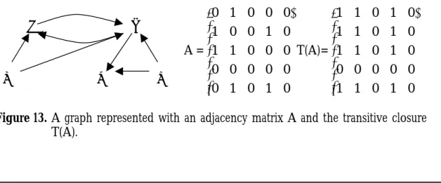
This thesis presents methods to analyse the dependencies between components. Traditional graph theory, as presented in [31,53], is used to organise the dependencies between components. The dependency graphs can be represented with matrices or adjacency lists. For calculating all direct and indirect dependencies in a system, different algorithms for transitive closure are used. Examples quoted are three algorithms from Warshall, Nuutila, and Eve and Kurki-suonio [28,43,59].
Voas [57] discusses the possibility of certifying components to assure the quality of the system. An important question to be answered before using a component in a system is: Does the component have a positive impact on the system? To be able to answer this question certain analyses of the system must be performed. It is important especially to know the dependencies between components in the system. This thesis presents a model for performing dependency analyses which can be utilised in implementing the Voas certification strategy.
1.3 Contribution
The main contribution of this thesis is a method which can be used for managing component dependencies when updating systems with new components. The problems of dynamic configurations and the importance of solving them to provide controlled updates of systems is presented. The prediction of the effects of updating the system is crucial for all types of computer-based systems and especially for safety-critical systems. The method for managing interactions between components in a controlled way with software configuration management is discussed in all chapters, but principally in sections 4, 5, 6 and in the included articles.
A prototype which explores dependencies and stores them under version control has been developed to implement the configuration model. The prototype has been used to analyse the Windows 2000 platform and its components.
Experience from real projects is needed to develop component-based systems. A gathering of such experience from software development using components is presented in a number of articles, which point out the existing problems with component-based software engineering. Four of the published articles have been selected to be included in this thesis. A short introduction to these articles is presented below.
▪ Development Experiences from a Component-based System
Presents experiences and background to the problems encountered in developing component-based systems. Published in Proceedings 7th Annual IEEE International
Conference and Workshop on the Engineering of Computer Based Systems Edinburgh,
Scotland, IEEE Computer Society, April 2000.
▪ New Challenges for Configuration Management
Presents the problems encountered in run-time configuration management and certain proposals for managing components. Published in System Configuration
Management, SCM-9, proceedings Toulouse, France, Lecture notes in computer science
1675, Springer Verlag, September 1999.
▪ Component Configuration Management
Introduces the idea of configurations placed under configuration control. Published in Proceedings, Asia-Pacific Software Engineering Conference, Workshop on Software Architecture
and Components Takamatsu, Japan, December 1999.
▪ Component Configuration Management for Frameworks
Shows how object oriented frameworks can be implemented with components using COM. Published in ECOOP Conference, Workshop on Component Oriented Programming Nice, France, Springer workshop reader, June 2000.
The different articles are presented below with a short summary of their respective contribution and presentation of the specific contribution of each author.
1.3.1 Development Experiences from
a Component-based System
Building software systems with reusable components has many advantages. If the reuse concept is utilized on several levels of a system development, the development becomes more efficient, the reliability of the products is enhanced, and the maintenance requirement is significantly reduced. In this paper the different levels of component reuse, and certain aspects of component development are discussed. As an illustration of reuse issues, a successful implementation of a component-based system used for industrial process control is presented. The experience can be summarised in that it is better to invest more effort in creating an open and extendable architecture than to focus on the development of only current technologies.
Magnus Larsson contributes to this article with knowledge about the case study and the background, an analysis of different reuse aspects and the replacement of proprietary components with standard components. Ivica Crnkovic wrote the sections about requirements and development environment.
1.3.2 New Challenges for Configuration Management
When moving from monolithic to open and flexible systems a new issue relating to dynamic upgrades of components is introduced. It is important to have up-to-date
information about which components are installed in a system. To know this is a general problem since it is difficult to obtain configuration information from each component. Configuration management has been traditionally focused on the development phase; in particular, on managing source code, but now, when changes are introduced in component-based systems at run-time, new methods are needed. This paper identifies these kinds of problems and proposes configuration management routines for libraries and version interfaces for components.
Magnus Larsson contributes with background information about the problems of run-time configuration management and the sections about managing components and proposed CM for libraries and components. Ivica Crnkovic wrote the section about component compatibility.
1.3.3 Component Configuration Management
The problem of component identification is discussed in this paper. The components are usually binary units deployed in the system at run-time and the insight into their characteristics is not as clear as into those of the software units which we manage at development time. For external components, extensive tests can, to some extent, compensate for the lack of information. When the information about the components is gathered, it is possible to keep track of changes introduced in the system and their impact on the system. The change management process is similar to that for configuration management. This paper makes proposals for managing dependencies during run-time using software configuration management principles. The proposal is to identify component dependencies in a system and to have a tool able to browse these. Magnus Larsson wrote the sections about component dependencies and the browser. Ivica Crnkovic presented the introduction and the section about component management and SCM was a joint production.
1.3.4 Component Configuration Management for Frameworks
Object-oriented design frameworks are increasingly recognized as better components than objects. Frameworks can be expressed formally and later verified formally. An object in a framework can have multiple roles which are mapped in component interfaces. Objects can have multiple roles in different frameworks. This paper shows how object-oriented design frameworks can be implemented in COM and presents a discussion about how frameworks can be composed in a controlled way using configuration management techniques.
Magnus Larsson provided the COM implementation of frameworks and wrote the section on configuration management issues in collaboration with Ivica Crnkovic. Kung-Kiu Lau presented the ideas of frameworks and how to formalise them.
2 Component-Based Software Engineering
Component-Based Software Engineering (CBSE) is the discipline of developing components and developing products with components. Products are no longer developed from scratch; they are instead an assembly of components developed independently of the products. This means that components are developed without complete knowledge of their execution environment. To assembly components, proprietary code, which glues the components, is usually needed. This code is often referred to as “glue code” [18] and in certain cases, the glue may take a longer time to develop than the components concerned.
Object-oriented programming (OOP) had the same approach; objects were reusable entities that could be assembled as programs. Component-based development can be seen as an extension of object-orientation, but takes one step further. OOP binds the implementation to a particular class library and language. Smalltalk is one example in which the programmer is bound to the Smalltalk language and the classes provided in the environment. Components, on the other hand, are generally not bound to a particular language and they communicate through independent interfaces.
One common characteristic of object technologies and component technologies is that there are as many definitions of objects as there are of components. These definitions are elaborated upon in this section. Component-based systems are usually implemented within a particular component model. Different component models such as COM, EJB and CORBA will be described in section 2.2.
Patterns, as described in section 2.3, can be used to facilitate the understanding of the architecture of a system built from components. Patterns can also be reused in subsequent projects since the same architectural solutions often reappear.
This section ends with a description of component interfaces, followed by a discussion of component-based development.
2.1 Component Definitions
“Components are for composition. Nomen est omen”. [54] This is a quotation with which most people agree when discussing the nature of components. But to develop a precise and well-understood definition of a component upon which everybody agrees, is not an easy task. Many have tried, but the result is a flora of definitions which all differ slightly. Wallnau [17] presents four main definitions, representative of those emerging in the software industry.
1. A component is a non-trivial, nearly independent, and replaceable part of a system which fulfils a clear function in the context of a well-defined architecture. A component conforms to and provides the physical realization of a set of interfaces.
2. A run-time software component is a dynamically bindable package of one or more programs managed as a unit and accessed through documented interfaces which can be detected during run-time.
3. A software component is a unit of composition with contractually specified interfaces and explicit context dependencies only. A software component can be deployed independently and is subject to composition by a third party.
4. A business component represents the software implementation of an "autonomous" business concept or business process. It consists of all the software artefacts necessary to express, implement and deploy the concept as a reusable element of a larger business system.
Sametinger [50] defines a reusable component as a component which is a self-contained, clearly identifiable artefact which describes and/or performs specific functions and has clear interfaces, appropriate documentation and a defined reuse statement.
There are other ways of classifying components, for example, as internal and external components. Internal components are developed within an enterprise for use by internal projects. Usually these components encapsulate the core competence of the company. External components, on the other hand, are developed by a third party and usually for the general market. Examples of such components are generic user interface components and communication protocols. Product line components are a component category designed to fit into a flexible architecture which can be configured for different products within the product line [14]. There are also different levels of components as mentioned in [40], from small library components to large product components.[23] These different definitions of components are presented to demonstrate that it is not easy to arrive at a generally acceptable definition. However, before a component-based system can be designed, a specific definition must be agreed upon to establish the context for the developers.
Common to all these definitions is that a component shall provide interfaces, conceal the implementation and be independently deployable.
Szyperski’s definition [54] of a component is used in this thesis. A software component is a unit of composition with contractually specified interfaces and explicit context dependencies only. A software component can be deployed independently and is subject to composition by a third party.
2.2 Component Models
Component models are sometimes called component frameworks but because of the risk of confusion with other definitions of frameworks, the term model is used in this thesis. Models give significant support to the user by managing the infrastructure, making it possible for the user to concentrate on meeting the requirements without needing to develop the infrastructure. In a sense, the models themselves can be seen as components since they are used to minimize the development effort. However, they do not express external dependencies and are designated infrastructure components. Other examples are databases or operating systems.
Three major component models are used successfully today: COM [4], JavaBeans [7] and CORBA [6]. All have different levels of service for the application developer. Table. 1 shows the corresponding technologies for each level of service.
COM Java CORBA Basic components COM components JavaBeans CORBA objects
Distribution DCOM RMI CORBA IIOP Enterprise services COM+ EJB/J2EE CORBAServices
Table. 1. The different technologies used at different levels of service Distribution is by means of a communication protocol added to the basic component model. COM uses Distributed COM (DCOM), Java has Remote Method Invocation (RMI) and CORBA uses the Internet Inter-ORB Protocol (IIOP). Support for business components is available in COM+, EJB and CORBAServices.
There are differences between systems with components tightly coupled together and those with loose references between the components. Tightly coupled systems are tied together at build-time or with strong references, e.g. a shared library. With loose references, the components are connected to their fellow components as required and not during the build phase. For such systems, it is much more of a challenge to determine, when starting, the final appearance of the system. To be able to predict the behaviour we need to know which components will cooperate. All three models presented in this section are loosely coupled with support for dynamic invocation and lookup.
The use of component models can be an appropriate way of beginning component development. If components are developed independently, it is highly unlikely that they will be able to cooperate usefully [30], because of a probable mismatch in the
requirements. The primary goal of component technology, independent deployment and assembly of components will not be achieved.
A component model supports components by requiring them to conform to certain standards and permitting instances of these components to cooperate with other components conforming to the model.
The key contribution of component models is the partial enforcement of architectural principles. By forcing component instances to perform certain tasks, the component model can enforce policies. E.g. a component model might enforce some ordering on event multicasts and thus prevent entire classes of subtle errors caused by glitches or races which might otherwise occur.
2.2.1 Component Object Model (COM)
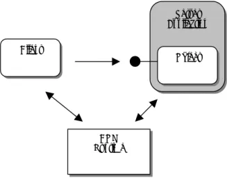
The Component Object Model [4], from the Microsoft Corporation, provides a model for designing components with multiple interfaces with dynamic binding to other components. COM is also a run-time environment, unlike CORBA, which is only a specification. COM is an open standard which has been implemented on many different platforms, but it has mainly been used on Microsoft Windows for which it was first developed. Components expose themselves through interfaces only. The interfaces are binary which makes it possible to implement the component in a variety of programming languages such as C++, Visual Basic and Java. A COM component can implement and expose multiple interfaces. Figure 1 shows how a client uses COM to locate the server components and then to request the required interfaces using the QueryInterface method.
Figure 1. COM establishes the connection between client and server and the client communicates directly with the server.
DCOM is the protocol used to make COM location transparent. The client talks to a proxy, representing the server and manages the real communication with the server.
Client Server Application Object COM Runtime
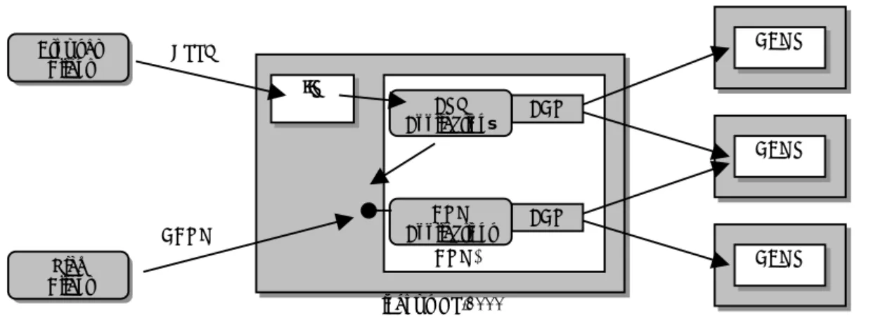
COM Applications COM+ IIS Windows NT/2000 DBMS DBMS DBMS ASP Applications Browser Client Rich Client HTTP DCOM ADO ADO
Figure 2. The principle of the use of COM+ in a three-tier architecture.
COM+ [4] is an extension of COM which includes support for transactions, directory service, load balancing and message queuing. Figure 2 shows how clients can connect, through an Internet Information Server (IIS) or DCOM, to the business logic, which is implemented with COM+. The business logic uses ActiveX Data Objects (ADO) to access the data in the databases. Compare this picture with the EJB technologies illustrated in Figure 3 to see the similarities.
2.2.2 Enterprise Java Beans (EJB)
Enterprise Java Beans [7], from Sun Microsystems, is a component-architecture for server-side components used to build distributed systems with multiple clients and servers. A Java Bean is a reusable component which supports persistency and can interact across all platforms supported by Java. EJB uses Java Beans but is much more than a component model. EJB provides support for transactions and security over a neutral object communication protocol, which gives the user the opportunity to implement the application on top of a protocol of choice. EJB is part of the Java 2 Platform Enterprise Edition (J2EE) [49] which includes many other technologies such as remote method invocation (RMI), naming and directory interface (JNDI), database connectivity (JDBC), server pages (JSP) and messaging services (JMS).
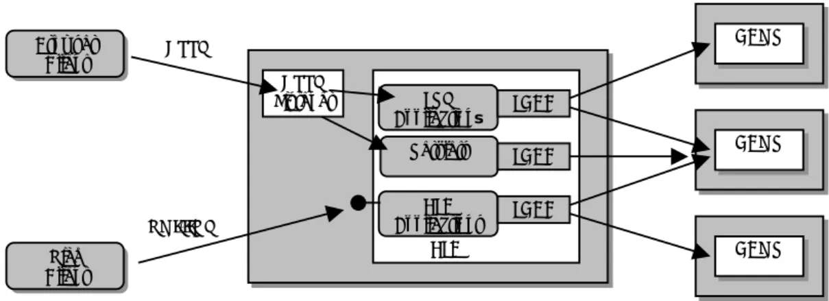
EJB Applications EJB HTTP Listener DBMS DBMS DBMS JSP Applications Browser Client Rich Client HTTP RMI/IIOP Servlets JDBC JDBC JDBC
Figure 3. The principle of the use of EJB in a three-tier architecture.
Figure 3 shows the architecture of a three-tier application using EJB. The clients connect to the server components through either a web server or directly, using remote method invocation (RMI). The server components which implement the business logic reside within an EJB container with support for transactions and security. The data is stored in databases which are managed by a database management service (DBMS) and are accessed through the data base connectivity component (JDBC). Java server pages (JSP) or servlets are used when thin web clients access the system through the Internet. Compare Figure 3 with Figure 2 to see the similarity of the technologies used in the COM+ environment.
A JavaBean is a special case of an ordinary Java class. To make a JavaBean an Enterprise bean the JavaBean must conform to the specification of EJB by implementing and exposing a few required methods. These methods enable the EJB container to manage beans in a uniform way for creation, transactions etc. The clients of an enterprise bean can vary widely, for examples a servlet, an applet or another enterprise bean. Since enterprise beans may call each other, a complex bean task might then be divided into smaller tasks and handled by an hierarchy of beans. This “divide and conquer” procedure is very efficient.
There are two different kinds of enterprise beans: session and entity beans. Session beans live as long as the client code which calls it. They represent the business process and are used to implement business logic, business rules and workflow. Entity beans model data and are often used by session beans to represent the data they use.
EJB is designed to interact with CORBA implementations and access CORBA objects transparently. There is also a bridge between COM and EJB which can be used to make systems even more open. The adapter pattern [29] can normally be used to implement various bridges between object models.
2.2.3 Common Object Request Broker Architecture (CORBA)
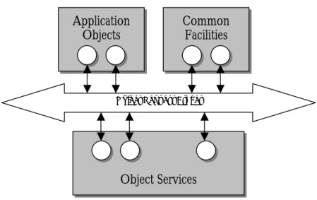
The Common Object Request Broker Architecture (CORBA) [6] is a standard developed by the Object Management Group (OMG) at the beginning of the nineties. The OMG supplies industry guidelines and object management specifications to provide a common framework for integrating application development. Primary requirements for these specifications are reusability, portability and interoperability of object-based software components in a distributed environment. Figure 4 shows how CORBA is part of the Object Management Architecture (OMA), which covers object services, common facilities and definitions of terms.
Figure 4. The parts of the Object Management Architecture.
Object services include naming, persistency, events, transactions and relationships. These can be used when implementing applications. Common facilities provide general-purpose services such as information, task and system management. All services and facilities are specified in IDL. An object request broker (ORB) provides the basic mechanism for transparently making requests and receiving responses from local or remote objects. Requests can be made through the ORB irrespective of the service location or implementation. Objects expose their interfaces using the Interface Definition Language (IDL) as defined in the CORBA specification.
Object Request Broker
Object Services Application
Figure 5. Clients communicate transparently with the server with Remote Procedure Calls (RPC).
Objects are stored in an interface repository where they can be found and activated on demand from the clients. Figure 5 shows how the client communicates with the server through remote procedure calls (RPC). RPC is a location-transparent way to communicate; the real communication is by means of proxies and stubs. The stubs and proxies are generated from the IDL specification which each object provides for its interfaces.
2.2.4 Comparison of COM, EJB and CORBA
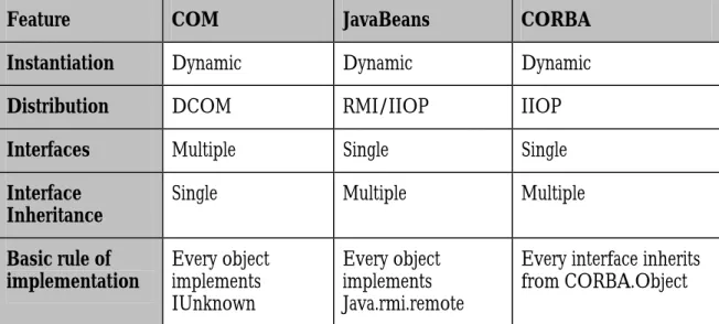
To be able to compare the different technologies it is important to compare them at the same level of service. Since the basic level of EJB is JavaBeans, JavaBeans is to be compared with COM and CORBA. Many features of the component models presented are similar but there are also differences. To explain the differences, a short comparison of the three models is presented in Table. 2.
Feature COM JavaBeans CORBA
Instantiation Dynamic Dynamic Dynamic Distribution DCOM RMI/IIOP IIOP Interfaces Multiple Single Single Interface
Inheritance Single Multiple Multiple Basic rule of
implementation Every object implements IUnknown
Every object implements Java.rmi.remote
Every interface inherits from CORBA.Object Application Object Client Proxy Stub RPC
Feature COM JavaBeans CORBA Dynamic
invocations Dispatch interfaces Dynamic wiring with reflection and introspection
Dynamic Skeleton Interface (DSI) and Dynamic Invocation Interface (DIII) Type information Type libraries and
ITypeInfo interface Introspection Interface Repository Mapping of object name to implementation Handled by the Registry Handled by the RMIRegistry Handled by the Implementation Repository Event model Advice sink model Components declare
outgoing events and registers for
incoming events.
Event Interfaces
Platforms Primarily Microsoft but also available on all major platforms. Independent, Needs Java environment Each vendor of CORBA implementations provides products for different platforms. Security User authentication
and authorization, data encryption and integrity checking.
User authentication
and authorization. Secure domains, data encryption and integrity checking.
Table. 2. A comparison of concepts in COM, EJB and CORBA
The different models have advantages and disadvantages and it is therefore difficult to determine which is the “best”. When a system is designed a range of models must be considered, depending on what us required of the product. Often when the platform is chosen, the selection of component model is not so difficult. For instance if the target environment is C++ on top of a mix of UNIX and Windows platforms, CORBA is probably the best choice. In the same way EJB is more suitable for a heterogeneous Java language environment. A third example is the choice of COM when the target is Windows based PC machines.
2.3 Patterns
Design patterns were introduced to permit the reuse of successful designs [29]. Each pattern describes a problem, which occurs repeatedly in the environment, and then describes the core of the solution to that problem. By means of design patterns, knowledge of good software design can be documented and the experience gained within software projects becomes widely applicable. With design patterns, a common design vocabulary is introduced, simplifying communication between engineers. Design patterns may be components themselves but according to several definitions a component shall be executable and patterns cannot be executed. Rege [47] introduced four useful patterns for component-based development. These patterns are described below and can be used for designing with components.
The Dynamic Factory pattern provides a definition of an interface with operations for the creation of components. Components are bound at a late stage, i.e. the concrete implementation is determined at runtime. They can thus be created by different vendors and composed dynamically to give a specific machine.
The Aggregation pattern aggregates components into larger entities. Components can be loaded as separate entities and be configured dynamically. Other aggregates which extend the functionality can be associated with those already existing. Components are tied together into aggregates.
The Embedding pattern provides a definition of a uniform interface to one or more components. This makes it possible to adjust the interface and the components implementation to the specified requirements. A component may not be reusable because its interface or part of its implementation does not match the specified requirements of the application. The embedding pattern can then be used to wrap the component to fulfil the requirements. An example of how components can be wrapped to modify the requirements is given in [57].
The Propagator pattern defines a network of coupled components such that if the state of one component changes, the dependent components are notified and may be adjusted. In a system, there is a logical interdependence between the states of the components. If one component changes its state, it is necessary to notify all dependent components, since these may need to adjust their states accordingly.
Patterns can be used to understand and design a complex configuration of components. Understanding the architecture is crucial when implementing a system. Design patterns are related to architectural styles as presented by Bass et al [13] and can be used as metaphors communicating the architecture and design of component-based systems.
2.4 Interfaces
Components communicate through interfaces which the user accesses when interacting with the components. The actual interaction with the component is performed using connectors, i.e. Connectors mediate interactions between components [52]. If an interface is changed the user needs to know that it has changed and how to use its new version. When the interface is changed, the user frequently becomes aware of the change too late, when, for example, attempting to access or link with the component. The component providers must therefore announce the change before implementing it. Functions exposed to the user are usually designated Application Programmable Interfaces (API). If there is a change in the API, the user must also recompile his code. This is the case with compiled languages such as C/C++ but not interpretative languages such as Smalltalk or Java.
In the object-oriented programming world, an interface is a set of public methods defined for an object. The object can usually be manipulated only through its interface. In C++ the user need only recompile the code when an interface, referred to from the code, is changed. There is also the additional drawback that the user of the class must use the same programming language throughout the whole development.
Separating the interface from the implementation is one way of avoiding this tight coupling. This kind of separation is performed with binary interfaces in CORBA [6] and COM [4]. Binary interfaces are defined in an interface definition language (IDL) [6,15] and an IDL compiler, which generates stubs and proxies, making the applications location-transparent.
By defining interfaces as unchangeable units, COM solves the interface versioning problem. Each time a new version of the interface is created, a new interface will be added instead of changing the older version. A basic COM rule is that an interface cannot be changed once it has been released. This makes couplings between COM components very loose and makes it easy to upgrade parts of the system independently. Even if an interface has not been changed, its implementation can be changed. This increases the flexibility of possible updates, but also introduces the possibility of uncontrolled effects. For this reason, it is of interest to know if the implementation has been changed.
2.5 Commercial Off-The-Shelf Components
Buying commercial off-the-shelf (COTS) software is a common way to gain functionality without needing to develop everything from scratch. Components are sometimes wrongly referred to as COTS software. Certainly, components may be COTS but this does not mean that COTS must be components. A vendor sells COTS products as unmodified units which can be used in developments. For example, a class library linked to a source code is not a component but it is COTS software. Components, however, are often distributed as COTS software, which means that the issues with COTS apply to component-based development as well as to other developments. Development with COTS components has many advantages [58]:
▪ Functionality is instantly accessible to the developer.
▪ Components may be less costly than those developed in-house.
▪ The component vendor may be an expert in the particular area of the component functionality.
Despite all the advantages, there are several disadvantages [36]:
▪ Often, only a brief description of its functionality is provided with a COTS component.
▪ The component carries no guarantee of adequate testing.
▪ There is no, or only a limited description of the quality of the component.
▪ The developer does not have access to the source code of the component.
To make the decision to buy or to build is not easy, knowing all the disadvantages. COTS components are typically “black boxes” without their source code or other means of introspection available. Developers must identify certain properties of COTS components to integrate them properly with a system under development. Examples of relevant properties are functionality, limitations, correctness, preconditions robustness and performance. To determine its properties, extensive testing of the component is necessary. There are various approaches to this kind of testing, e.g. random, “black-box” and “white-“black-box” test generators.
Thane [56] presents a model for determining the reliability of components. To acquire confidence in a component it must be supplied with a contract and be tested with a certain input. A contract specifies the functionality and the run-time conditions for which the component has been designed, i.e. assumptions about inputs, outputs and environment. If the component supplier provides such a contract, it can be used to calculate the probabilities of the occurrence of errors. Evidence based on the component’s contracts and the experience accumulated must be obtained. The environment must be considered when components are integrated in new systems; the input domain may differ considerably from the input domain for which it was tested. Confidence in a component’s reliability is only warranted when the component is used in the environment for which it is intended.
COTS components with same functionality can be categorized in groups even if their implementations are different. Components in the same category can be exchanged transparently if their interfaces are the same. If the interfaces differ, wrappers can be used to provide the same interface towards the user. When more than one vendor provides components with the same functionality, it is advantageous to design the system for component exchangeability. An architecture which supports the exchange of components is more stable, e.g. if the support for a component selected is discontinued a new component can replace the obsolete.
2.6 Component-based Development
This section describes the differences between developing components and developing with components. It is important to make this distinction to make it clear how to use different methods. The developer of a component must think about how to make the component open to integration with other components and less about how to integrate other components.
Recommendations to developers and users of components are given in this section. As a result of studying different aspects of component-based systems, we provide a list of recommendations for this area. The section is divided into two parts, one for the component developer and one for the component integrator (the user who develops systems incorporating components).
2.6.1 Developing
Components
There are many known difficulties to be encountered when developing components. It is generally difficult to design and develop a component intended for unknown products. Developing internal components to fit into a product line is therefore easier [14]. Satisfying all the requirements demanded of a component by customers is not easy, as the requirements are often conflicting and impossible to fulfil. To determine the “right” requirement is an important issue for the component developer. To develop a generic component takes more time. Lampson [37] states that it takes around three times more effort. If the time required is too long, the time to market may be prolonged and the market window might be too small to make a profit for the component.
When developing and designing components, the following is recommended:
▪ Always document all the features of the component. Do not restrict the documentation to functionality, but document all other properties such as performance, resource consumption, limitations and robustness.
▪ Provide test-suites with the component so that the customer can test the component in their own environment. It is extremely important to test an imported component in the environment in which it is to operate. Remember the Ariane 5 rocket explosion [41] which was due to a change in the environment requirements and not in the software design.
▪ Provide source code to help the application developer understand the semantics of the component.
▪ Design the components so that they can be integrated into existing component models. Describe models in which the component works and describe how to make it work with other models.
▪ Carefully generalize the components to permit reuse in a variety of future contexts. Note, however, that solving a general rather than a specific problem requires more work.
▪ Make sure that the application developers can adapt the component to their requirements. This can be done with sink interfaces to which the user adds an interface to the component so that the component can utilize that interface to communicate with the user.
2.6.2 Developing with Components
Development with components is a complex process as there is always a trade-off between buying and developing the components concerned. It is generally better to buy general-purpose components, e.g. operating systems, databases and user interface components. Many different aspects must be considered before choosing an existing component over an internal. The development of proprietary components takes resources, requires maintenance and support. Before making decisions when building applications with components, the following questions and thoughts should be considered:
▪ The market for a product is limited in time and it is therefore important to deliver a.s.a.p. There is a risk that a component vendor may discontinue support, and if the support is discontinued, there may be a loss of time and a postponed release. The risk is considerably lower with a well-established vendor.
▪ The functionality provided by the component may not remain the same over time, forcing the integrator to create wrappers, which provide or prevent functionality, around the components. If the support from the component vendor is inadequate, this could be a serious issue.
▪ The functionality of the component may be more than actually needed, requiring restrictive wrappers to be written. In this case unwanted functionality is paid for unnecessarily. The use of unintended functionality may cause problems.
▪ If the source code is in fact available from the component vendor, is it really maintainable if something goes wrong?
▪ A malfunction in the component may cause an error in the product. The end user wants the product to function without needing to think about the internal design. The product vendor must solve problems arising even if the error is in the third-party component.
▪ If an external component is customized for a product, it makes the product strongly dependent on the component vendor. The vendor can then set his own price for continued support of the component.
There are many more issues surrounding CBSE to be addressed before making decisions on how to design a system with components. Takeshita [55] lists several questions concerning metrics and risks. The subtopics discussed are: metrics for components, difficulty in acquiring proper components, metrics for completed applications, insufficient analysis/design and architecture mismatching, insufficient technical support, use of low-quality components, cost-related risks and difficulty in managing computing in enterprises.
Josefsson [35] presents the following recommendations to the component integrator:
▪ Make a thorough evaluation of the component suppliers. Are they suitable as suppliers? Do they have good quality products and support? Check their financial position for economic stability.
▪ Ensure that the legal agreement with the supplier is comprehensive. This may save time and efforts if the supplier goes out of business or if they refuse support of their component.
▪ Create good and long term relations with the supplier for better cooperation.
▪ Limit the number of partners and suppliers. Too many will increase the costs and the dependencies.
▪ Buy “big” components where the profit is greatest. The management of too many small components can consume the profit.
▪ Adjust the development process to a component-based process.
▪ Have key persons assigned to supervise the component market, monitoring new components and trends.
▪ Try to gain access to the source code. Through special agreements with the vendors etc.
▪ Test the components in the target environment.
These recommendations do not provide a complete solution to all the problems which may occur, but they indicate that developing for and with components must be performed carefully.
2.7 Development Cycle
The development cycle of a component-based system is different from those of the traditional models, such as the waterfall, iterative, spiral and prototype models.
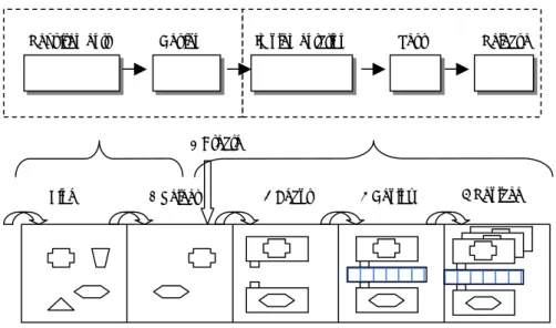
Development with components differs from traditional development. There is, for example, a new component development process for CBSE [16] which differs from the traditional waterfall model. A similar process for development of COTS components which emphasizes requirements, design, coding and integration is described by Morisio et al [42]. Figure 6 shows a comparison between two different development processes. Determining requirements and designing in the waterfall process correspond
with the finding and selection of components. Implementation, test and release correspond to create, adapt, deploy and replace.
Figure 6. An example of a development cycle with components compared with the waterfall model.
The different steps in the development with components process are:
1. Identifying components which could be used in the product. All possible components are listed here for further investigation.
2. Selecting the components compatible with the requirements of the target product. 3. Creating proprietary components to be used in the product. These components need
not be found since they are developed inside the enterprise.
4. Adapting the selected components to suit the existing component model or requirement specification. Some components need more wrapping than others.
5. Composing or deploying the product. This is done with a framework or infrastructure for components.
6. Replacing old versions of components with new, i.e. maintaining the product. There may be bugs to be eliminated or new functionality to be added.
In Figure 6, the find phase appears to replace the determination of requirements. The figure should be interpreted however, as showing that finding and requirement determination are performed in the same phase of development. There is a need for requirement determination by means of analysis, design and testing when performing component-based development.
Different technologies are available to support developers at each step. There are tools such as Agora [51] and Jcentral [8] to find components while Cool: Spex [1] from Sterling software can help with the selection process. There is also COMCAD [46], which supports the deployment of COM components.
1 Find 2 Select 4 Adapt 3 Create
5 Deploy 6 Replace Requirements Design Implementation Test Release
3 Configuration Management
Configuration management (CM) is the control of the development and evolution of complex systems [19,27]. A complex system is characterized by a large number of components developed by many persons with usually rigid time constraints and quality requirements. These kinds of systems are often developed concurrently and are intended to last for longer periods of time, between ten and twenty years. Version control is usually used in all types of projects. When it comes to more complex and sophisticated projects, a systematic use of configuration management methods is needed. Change, build, release and workspace management are other disciplines covered by CM. This section gives a brief introduction to all of these disciplines.
3.1 Version Management
An element of software or hardware placed under version control is designated a
configuration item. The most common example of a configuration item is a source code file
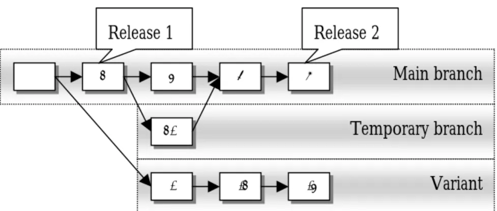
but executables and documents might also be considered to be configuration items. Version control covers the management of different versions of items, usually represented by a tree structure [12]. Version management supports concurrent development in which the concurrent versions are usually implemented as branches. Selected versions of configuration items together form a baseline. Tags are used as marks or labels to identify a specific version of an item. It is possible to tag all the different configuration items included in one release of a system, for later retrieval of the very same configuration. This may be needed e.g. when bugs must be eliminated. The same version of a configuration item can be included in many baselines by attaching multiple tags to it.
Figure 7. Variants are branches which do not merge back into the main stream.
Items are checked out and in from the version database when needed. There are different models for concurrent work but the most common is to use locks on the configuration items. When a version of a file is to be modified, the locking mechanism which prevents concurrent work is used. After the file is locked the developer can be
Main branch Temporary branch Variant 1 2.1 2 4 5 1.1 1.2 1.3 3 Release 1 Release 2
sure that no other person is modifying the same file. When the developer is ready, the file is checked in to the version repository and the lock can be is released. If a developer intends to develop a locked file it is possible to create a temporary branch to permit this. Another model is to permit concurrent development with an optimistic approach. In this model the files are not locked but the file is checked when returned to the database. If the file has been changed in the meantime, a merge will take place with the developer responsible.
Branches are used to permit work in parallel or to create multiple variants of a release as shown in Figure 7. A branch can span over many different versions and is thereafter usually merged back into the main branch. An example of this is when a developer has created a branch 2.1 because the original version 2 was locked by another developer. After both developers have finished their assignments, branch 2.1 can be merged with the main branch as version 4. Version 4 in the main branch will now contain the changes made in both versions 3 and 2.1. Another example of the use of a branch is when there is a need for extra functionality to be added to subsequent releases but not to the current release. To accomplish this, the new functionality is inserted in the branch until the subsequent release and the functionality is then merged. If the functionality is not merged back into the main branch, the branch is designated a variant.
With version management, it is possible to control configuration items included in a release of a complete system and it is also possible to recreate the very same configuration on demand with the help of baselines.
3.2 Change Management
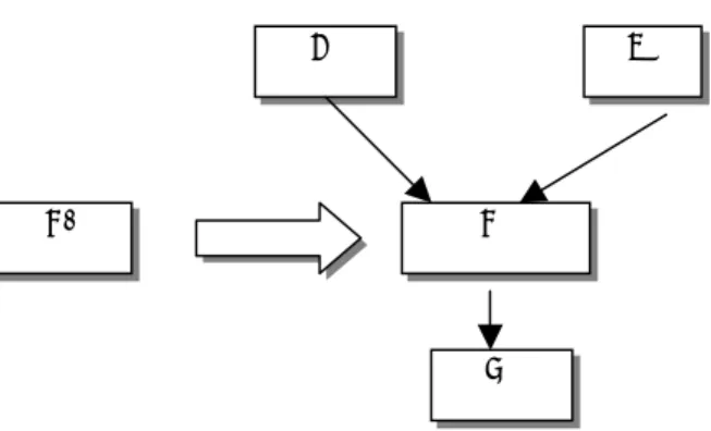
The reasons for changes are multiple and complex. Changes can originate from many different sources. Change management handles all changes in a system. The reason for a change can be an error, improvement of the component or added functionality. Change management includes tools and processes which support the organization and track the changes from the origin to the actual source code [22]. Examples of Change Management tools are PVCS tracker [9], Visual Intercept [10] and Clear Quest [3].
Figure 8. An example of a change process in which the customer files requests to the support organization.
When a change is initiated, change requests are created to track the change until it is resolved and closed. Figure 8 shows how a customer requests a change to correct an error in the system. The support organisation receives the change request, taking direct action and solving the problem if possible. If they cannot address the issue, the request is passed to the next instance. The configuration control board (CCB) analyses the
Support CCB
Develop Test Customer
change request and decides which action is to be taken. If the change is approved, the change request is filed to the developer responsible for implementing the change. When the developer has performed the change its status becomes “implemented” and a test is performed. When the subsequent new release is to be built, the CCB decides which changes are to be included. The customer receives a patch with the new release including documentation of the changes made in the new release.
Various tools are used to collect data during the process of tracking a change request. Change management data can be used to provide valuable metrics about the progress of project execution [24]. From this data it can be seen how many changes have been introduced between two releases. It is also possible to check the response time between the initiation of the change request and its implementation and acceptance.
3.3 Build Management
Build management supports the user by collecting source code for a particular release and
then using build tools, such as Make to create configurations. Make describes the dependencies between source code files at build-time and ensures that the dependent source code is built in the correct order. Ongoing research for automatic assembling of components, shows that it is very difficult to apply build management to component-based systems. Zeller [61] proposes the use of description logic to assemble components in design time. This does not solve however, the problem with dynamic configurations in run-time.
Daily builds can be performed when build management is supported. If the system is built every day the integration time is reduced, since broken dependencies and faults are discovered early. The daily build process also permits rapid development and early testing of the system. Support for parallel development with version control which resolves inconsistencies is required for daily build [44].
3.4 Release Management
The identification and organisation of all documents and supplements incorporated in a release is designated release management. It is possible with appropriate release management to create installation kits automatically to ease the task of the build manager. The build manager is responsible for providing the finished product with the correct configuration and features. Products such as Windows installer and Install shield [11] can be used to create installation kits. Hoek et al [33] describe a prototype, designated Software Release Manager (SRM), which supports both developers and users in the software release management process. SRM incorporates the concept of components and helps in assembling them into systems. Dependencies are explicitly recorded so that users can investigate and understand them.
3.5 Workspace Management
Introducing CM in an organization is cumbersome without effective support from tools. Changing an existing culture requires massive education, support and not least motivation. To motivate developers to use all the tools and methods available with CM, support for integrated tools in the development environment is needed. Developers want to work independently of the configuration management, this alternative being denoted workspace management. Developers usually focus on solving particular problems and have less interest in administrative tasks. An example of integrated features is when the developer “logs-in” to a project environment in which project structures and data repositories are already prepared for the developer. The developer then enters a transparent environment in which the development with configuration management is handled behind the scenes. This approach is adopted in such major configuration management tools available on the market today as Clear Case and Continuus [2,5].
3.6 Related Work
Distributed and parallel development is related to component-based development since the sub-systems delivered are often treated as separate entities. In distributed development, a distributed database for all configuration items is needed. This model does not suit the component-based approach since most components are developed independently using a variety of tool sets. External components can be treated as outsourced parts of a project with more restrictions on source code. A model for outsourced software development is presented in [12]. The outsource model gives more control to the integrator since he is a direct customer to the component provider and can require desired functionality for a specific target environment.
When a CM process is to be defined, different issues for users of the CM system must be considered [25] and the user’s roles must be defined. The CM system must have integration capability with existing development tools for transparent workplace management. To obtain support for build and release tasks, the degree of automation must be defined and the desired level of automation achievable by using the existing tools must be known. These issues must be considered when a configuration management process for component-based development is defined.
4 Dynamic Configurations
Dynamic configurations are needed to permit architectures to evolve during the life-time of a system. This occurs in practice when components create instances of other components during the system execution. Architectural Description Languages (ADL) can be used to express such architectures [52]. A system with a configuration of components in which the components may be replaced with new components is designated a subject of change, i.e. its contents change during its lifetime. Figure 9 shows an example in which components are replaced. Such a configuration is dynamic, since its components can be updated after the configuration is first deployed. A static configuration has the same set of components over its lifetime and nothing changes after the system is launched. For example, a simple program in which all its elements are statically linked together into one monolithic program.
Figure 9. Component C1 is replaced dynamically with component C2.
One example of a dynamic configuration is a PC running with executables and shared libraries which might be upgraded during runtime, another is a control system in which the control algorithm component is detached from the memory and a new component is inserted. Configuration management typically addresses this type of problem with identification, versions and dependencies but has not been applied to the particular issue of dynamic configurations. These issues have been explored in [38,39].
A configuration consists of a number of components which interact to perform the task of the system. Traditional CM can very well be applied to the development of the component but it cannot handle systems in which the configuration might change during run-time. Examples of systems in which the configuration might change are: web applications, systems built on component models with dynamic linking and real-time systems in which tasks might be changed on the fly. Applications are also written today which upgrade themselves when needed, Real player for example which checks with the home server for newer versions each time it is invoked. The management of systems in which components or applications upgrade themselves without notification is a challenge. Imagine components using an other component which suddenly upgrades itself. How is deterministic behaviour possible in such a system?
A1 B1
C1
C2
Another example of a system which configures itself dynamically in different environments could be a personal device connected permanently to the internet. When the device is used on the owner’s premises, high-speed communication without security might be acceptable. But when the device is used outside the company building, a more secure, slower connection must be used. This kind of systems must be reconfigured dynamically. How can the function be guaranteed if it is not know before what components are to work together?
Run-ti