Volume 2, Issue 11 (August 2012), PP. 32-41
Neural network based shunt active filter for harmonic reduction:
A technological review
V.V.Appalanaidu Menda
1, B Sankaraprasad
2, Kotyada Kalyani
31
Department of Electrical Engineering, st.Theresa Inst .of Engg &Tech, Garividi-535101
2,3 Associate Professor,Department of Electrical Engineering, st.Theresa Inst .of Engg &Tech, Garividi-535101
AndhraPradesh.
Abstract––The paper attempts to improve shunt active power filter performance using neural networks. Shunt Active Power Filters (SAPF) are one of the viable solutions to eliminate the power line harmonic/reactive currents generated by nonlinear loads and improve the power factor. Design and implementation are studied for a neural-network-based controller to govern the dynamics of linear processes. The advantages of using neural networks for modeling non-linear processes are shown together resulting implementation of the neural controller is able to eliminate the most significant obstacles encountered in non-linear systems.
Keywords––Active power filter, Artificial neural networks, Harmonics mitigation, Power electronics, Power quality, Voltage source inverter.
I.
INTRODUCTION
Power electronics based electronics based devices/equipments are a major key component of today’s modern power processing, at the transmission as well as the distribution level because of the numerous advantages offered by them. These devices, equipments, nonlinear load including saturated transformers, arc furnaces and semiconductor switches and so on, draw non-sinusoidal currents from the utility. Although these power electronics devices have benefited the electrical and electronics industry, these devices are also the main source of power harmonics in the power system. These power harmonics are called electrical pollution which will degrade the quality of the power supply. As a result, filtering process for these harmonics is needed in order to improve the quality of the power supply. Thus, active power filter seems to be a viable alternative for power conditioning to control the harmonics level in the power system nowadays.
Harmonics have a number of undesirable effects on the distribution system. They fall into two basic categories: short-term and long-term. Short-term effects are usually the most noticeable and are related to excessive voltage distortion. On the other hand, long-term effects often go undetected and are usually related to increased resistive losses or voltage stresses. In addition, the harmonic currents produced by nonlinear loads can interact adversely with a wide range of power system equipment, most notably capacitors, transformers, and motors, causing additional losses, overheating, and overloading. These harmonic currents can also cause interferences
II.
ACTIVE FILTERS
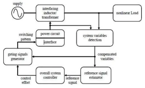
The basic principle of APF is to utilize power electronics technologies to produce specific currents components that cancel the harmonic currents components caused by the nonlinear load. Figure2.1 shows the components of a typical APF system and their connections. The information regarding the harmonic currents and other system variables are passed to the compensation current/voltage reference signal estimator [11]. The compensation reference signal from the estimator drives the overall system controller. This in turn provides the control for the gating signal generator.
A three-phase shunt APF is typically composed of a three-phase bridge converter and control circuitry. Most of theprevious control approaches need to sense the load current and calculate its harmonics and reactive components in order to generate the reference for controlling the current of a bridge converter. Those control methods require fast and real-time calculation; therefore, a high-speed digital microprocessor and high-performance A/D converters are necessary, which yields high cost, complexity, and low stability.
2.1 Classification of Active Power Filters
An unfavorable but inseparable feature of APF is the necessity of fast switching of high currents in the power circuit of the APF. This results in a high frequency noise that may cause an electromagnetic interference (EMI) in the power distribution systems [11]. APF can be connected in several power circuit configurations as illustrated in the block diagram shown in Figure2.2 In general, they are divided into three main categories, namely shunt APF, series APF and hybrid APF.
Fig2.2 classification of active power filters
2.2 Shunt Active Power Filter
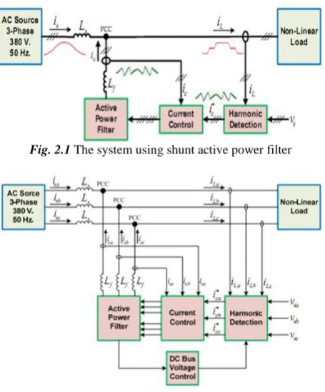
Shunt active power filter (SAPF) is commonly used as an effective method in compensating harmonic components in non-linear loads[10]. Fig. 2.1 shows the basic principle of SAPF in which APF is connected in parallel to the power system at a point of common coupling (PCC) between metropolitan electricity authority (MEA) and power users. The objective of SAPF is to minimize the distortion in power supply using four main components – harmonic detection, compensating current control, DC bus voltage control, and active power filter – as shown in Fig.2.2
Fig. 2.1 The system using shunt active power filter
Fig. 2.2 Three – phase shunt active power filter
III.
AN APPLICATION OF NEURAL NETWORK IN APF
There are many conventional techniques to detect and compensate harmonic current. ANN is one of the modern techniques which are used in many areas of application including harmonic eliminations [1][10]. Fig. 3.1 shows an architecture of three-phase diagram of neural network controlled SAPF. A NN is used to control the compensating current injection with SAPF.
Fig. 3.1 the active power filter control using NN approaches
From the review several IEEE papers, it shows that neural network is employed to substitute a harmonic detection component for the following reasons [10]:
1. To increase the processing speed, response speed, and convergence speed. 2. To increase the robustness.
3. To increase the efficiency and performance of the algorithm. 4. To increase the steady-state stability.
5. To increase an accuracy, precision, and validity of the evaluation process. 6. To increase an adaptive ability, so that it can response in real time. 7. To increase tracking ability.
8. To provide the optimal solution.
NN is easy and convenient to use as a substitution of the current control component. Furthermore, the following reasons are also given as the merit of the NN for current control process[10].
1. To increase the performance and efficiency of the algorithm in order to improve power factor. 2. To increase an accuracy, precision, and validity of the process.
3. To eliminate the threat of resonance.
4. To increase processing speed, response speed. 5. To increase the steady-state stability. 6. To reduce the switching frequency.
IV.
DESIGN CONSIDERATION FOR APF CONTROLLERS
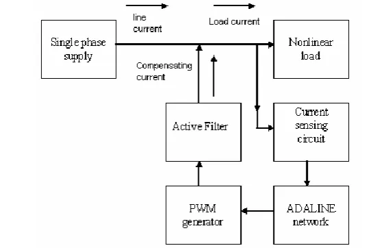
The block diagram of the proposed power line conditioner using active power filter is shown in Fig.4.1. The proposed Modular Active power filter connected to the electric Distribution system. The line current signal is obtained and fed to an ADALINE which extracts the fundamental components of the line current signal. In the controller block, fundamental component is compared with distorted line current to generate modulating signal. This modulating signal is used to generate Pulse-Width Modulated (PWM) switching pattern for the switches of the active line conditioner module. The output current of the active filter is injected into the power line.
The injected current, equal-but opposite to the harmonic components to be eliminated. Harmonics are suppressed by connecting the active filter modules to the electric grid [3][4].
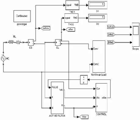
Fig.4.2 consists of a single phase fully controlled converter feeding RL load, Active filter and its ANN based control circuit. Fig.6 shows the details of control block using ANN. In the control block an improved scheme is proposed in which only the actual Load current is given to adaptive neural network and the reference current is obtained [5][6]. The load voltage is given to a DC regulator with a simple PI controller which gives the actual filter current and which is compared with reference current the gating pulses to IGBTs are provided through a hysteresis band comparator
Fig 4.2: Simulated circuit diagram of ANN based active filter connected to non-linear load
4.1.1 Design of Low Pass Filter for Reference Current calculation
The reference current calculation for low pass filter for balanced load is
The d-axis current for balanced load can be written as.
Similarly for unbalanced load
It can be seen from equations (4.4) and (4.5) that the first are the fundamental component of the load current and both are of DC values [7]. The lowest frequency in the d-axis current is the third harmonic for the balanced load and the fundamental frequency for the case of unbalanced load. Thus, to obtain the fundamental component for both the cases of
balanced and unbalanced loads, the cutoff frequency
a must lie between the DC frequency (0 rad/sec) and the4.1.2 Design of Current Regulators
The choice of cutoff frequency
f in the simplified analytical model will influence the line current trackingcapability of the active power filter. To obtain a fast response and low overshoot for the current of an active power filter, a
higher value of
f must be chosen. Unfortunately, the maximum value is limited by the maximum IGBT device switchingfrequency.
4.1.3 Design of DC-link Voltage Regulator
For the sake of simplicity in the design of a DC-link voltage regulator, the cutoff frequency
dc of a low -passfilter in the voltage detection block is equal to
athis givesThus, the delay time constant
T
dcis equal to 10 ms and equation can be written as.For design convenience of controller parameters, reduced-order operation is exercised for equation (4.7) to obtain the following standard second-order transfer function.
To obtain low overshoot for the DC-link voltage, the damping coefficient = 0.707 is chosen. The corresponding proportional gain of a DC-link voltage controller is
Equation (4.11) reveals the dependence of the proportional gain on the DC-link capacitance
C
2 DC-link voltage commandV
dc *2 peak value of phase voltage
V
m and delay timesT
f andT
dc .)
(
2
1
dc f nT
T
--- (4.12)Finally, substitution of the system parameters yields
K
pdc= 0.381 and
n=70.15 rad/sec. The value ofK
pdc=0.381 isreasonable because the limiting value for
K
pdc for stable operation is 96.71.4.2 Design Consideration for APF Controller
4.2.1 DC-Link Capacitor Design
The output dc-link capacitor of voltage source converter is determined by the output voltage ripple. The equation is given by
--- (4.13)
Where Vomax , Vomin is the peak to peak of the output dc-link voltage ripple.
4.2.2 Selection of APF Inductance
The concept of the proposed control is using one-cycle control to implement the control key equation as follows: Rs.ieq =Vm. (1-d) --- (4.14)
Where
ieq = (2ip + in) (OR) (ip +2 in)
Similar to the peak current model control, there is the convergence condition.
The stability condition is given by
--- (4.15)
Where m1 is the ON slope of the input current and m2 is the OFF slope of the input current; mcis the equivalent slope of
the carrier signal, which is implemented by integrator with reset.
Considering that the load current is low frequency and the influence of load current can be neglected, we only concern the inductor current in the stability analysis, we have
Where
Therefore
The convergence condition is dependent on the angular angle of input voltage wt and the Vm, which is related to the output
power and input voltage. When the convergency condition is satisfied partially, the system will still be stable.
According to (4.17), convergence condition for region 0o~360o is given by
But Vm is related to input voltage and output power through (4.19) . It can be rewritten as
where η is the estimated efficiency.
4.2.3 Design of the Control stage:
The large-signal model for a single-phase APF in line cycle can be derived based on energy balance. Suppose the efficiency is 100%. The input power equal to the output power, that is
Where Re is emulated resistance and Pload is the load power and ic is the current flowing into the dc-link capacitor.
By definition, we have
Combination of the above equation yields
Considering the small ac signal disturbation, that is
Neglecting the influence of load power, substitution of the (4.26) equation into (4.27) and linearize by considering the following conditions
In addition, we can neglect the influence of input voltage disturbation by setting, then we can get simplified solution as
The transfer function from capacitor current to output voltage is given by
Therefore, combination of the above equations (4.27) &(4.28) yields the following transfer function:
V.
SIMULATION AND RESULTS
Simulations have been conducted for balanced and unbalanced loads using SIMULINK for different controller configurations. Switching frequency of the inverter is set at 10 kHz, and the dead time of the inverter is set at 2 μs. The controller took 36 and 42 ms to converge in simulations. The controller is found to operate satisfactorily. Finally, the performance of the proposed controller is compared with that of a traditional controller (such as synchronous reference frame based). The synchronous reference frame controller is simulated (using the cutoff frequency of the low-pass filter as 10 Hz). A 110-V 50-Hz main supplying a load of 3 kVA is considered.
Fig.5.1 three phase source currents
Fig 5.3 compensated source current of phase a, phase b, phase c
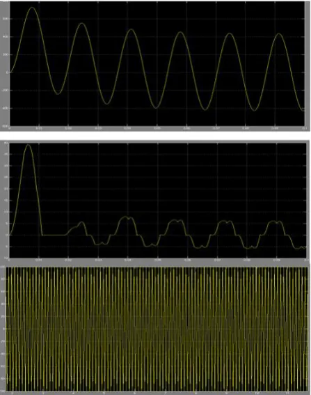
Fig 5.4 Performance of the APF with ADALINE (simulation results). Top waveform: Source current of phase A (scale: 5 A/div). Middle waveform: Load current of phase A (scale: 5 A/div). Bottom waveform: Compensating current of phase A
(scale: 5 A/div).
VI.
CONCLUSION
phase to that of the load current harmonics.. This will thus result in sinusoidal line currents and unity power factor in the input power system.
An integration of ANN-based controller for a shunt-type APF has been presented in this paper to improve the convergence and reduce the computational requirement. The algorithm is derived from an ANN based PWM controller used to regulate the dc-link voltage in the APF. This is followed by an adaline-based THD minimization technique. The results from Experiments match well with the simulation, confirming the usefulness of proposed technique.
REFERENCES
[1]. Avik Bhattacharya, and Chandan Chakraborty, “A Shunt Active Power Filter With Enhanced Performance Using ANN-Based Predictive and Adaptive Controllers” IEEE Transactions On Industrial Electronics, Vol. 58, No. 2, February 2011.
[2]. Yang Han and Lin Xu “Design and Implementation of a Robust Predictive Control Scheme for Active Power
Filters”. JPE 11-5-16
[3]. Chongming Qiao and Keyue Ma Smedley; “Three-Phase Bipolar Mode Active Power Filters”, IEEE Transactions on Industry Applications, vol. 38, no. 1, January/February 2002
[4]. Chongming Qiao ,Keyue M. Smedley and Franco Maddaleno; “A Single-Phase Active Power Filter With One-CycleControl Under Unipolar Operationn”, IEEE Transactions on Circuits and systems vol. 51, no. 8, august 2004.
[5]. J. Sebastian Tepper, Juan W. Dixon,Gustavo Venegas, and Luis Morh; “A Simple Frequency-Independent Method for Calculating the Reactive and Harmonic Current in a Nonlinear Load”, IEEE Transactions on Industrial Electronics, vol. 43, no. 6, December 1996.
[6]. Chongming Qiao, Taotao Jin and Keyue M. Smedley; “Unified Constant-frequency Integration Control of Three-phase Active-Power-Filter with Vector Operation”, 2001 IEEE.
[7]. Wang Yong, Shen Songhua, Guan Miao; “Three-phase Active Power Filter Based on Space Vector and One-cycle Control”, IEEE IPEMC 2006.
[8]. H.-H.Kuo, S.-N.Yeh and J.-C.Hwang; “Novel analytical model for design and implementation of three-phase active power filter controller”, IEE Proc.-Electr. Power Appl.. Vol. 148, No. 4, July 2001.
[9]. Mircea Lazar and Octavian Pastravanu “A Neural Predictive Controller For Non-linear Systems”
[10]. S. Janpong, K-L. Areerak and K-N. Areerak “A Literature Survey of Neural Network Applications for Shunt Active Power Filters”, World Academy of Science, Engineering and Technology 60 2011.