* To whom all correspondence should be addressed. Tel: +98-912-5032283; Fax: +98-611-3332066 E-mail: [email protected]
Dosimetric Parameters Estimation for
I-125 (model 6711) Brachytherapy Source
Ali Yadollahpour1, Mansour Zabihzadeh1,2*, Hadi Rezaee3 and Mostafa Feghhi4
1Assistant Professor of Medical Physics, Department of Medical Physics, School of Medicine, Ahvaz Jundishapur University of Medical Sciences, Ahvaz, Iran.
2Assistant Professor of Radiotherapist and Oncologist. Department of Radiation Oncology, Golestan Hospital, Ahvaz Jundishapur University of Medical Sciences, Ahvaz, Iran. 3M.Sc. Student of Medical Physics, Department of Medical Physics, School of Medicine,
Jundishapur University of Medical Sciences, Ahvaz, Iran. 4Associate Professor of Ophthalmology, Department of Ophthalmology,
Imam khomeini Hospital, Ahvaz Jundishapur University of Medical Sciences, Ahvaz, Iran. DOI: http://dx.doi.org/10.13005/bbra/1190
(Received: 01 November 2013; accepted: 11 December 2013)
Determining dose distribution around the applied sources in brachytherapy, especially ones with low-energy is so crucial in treatment designing. In this study dosimetric parameters of a brachytherapy source I-125 (model6711) were calculated using Monte Carlo simulation method.A homogeneity water phantom with dimensions of 30´30´30 cm3 were simulated with
MCNPX(2.6.0) code. A brachytherapy source I-125 (model6711) considering its details (materials, dimensions and its emitted spectrum) was located in the center of phantom. Positioning the source inside the vacuum sphere its air kerma strength, Sk, was calculated. Recommended dosimetric parameters were calculated by AAPM, TG-43 protocol in this phantom.The air kerma strength of the source I-125 (model 6711)was estimated equal to 0.557 cGycm2h-1mCi-1
in activity unit anddose rate constant was 0.885 cGyh-1U-1. The Radial dose function with 5
degree equation and correlation coefficient of 0.9989 was estimated by g(r)=-0.0001r4+0.0026r3
-0.0178r2-0.0970r+1.0995. Numerical amounts of the anisotropy dose functions and related
equations were calculated and compared with the reported data.In spite of low-energy emission photons and high dose gradients with radial distance, dosimetric parameters of source I-125 (model 6711)can be calculated by MCNPX Monte Carlo code with an acceptable accuracyand this can be used in brachytherapy treatment planning.
Key words: Brachytherapy, Source I-125 (model 6711), Radiation dosimetry, Monte Carlo simulation.
I-125 source is widely used for brachy therapy treatment of prostate permanent implant, eye malignant tumor, brain temporary implant and other types of cancers1,2. In this method, several sources are usually placed around the target in order to deliver the highest dose to the tumor target and the lowest dose to the surrounding tissue3,4.
potentialin particle transport and not dealing with the practical problems of dosimetry for the evaluation of diametric parameters along with practical measurements3, 5.
Accordingly, Group TG-43 of Medical Physics Society of America AAPM proposed a protocol to determine the necessary parameters for using radioactive sources in brachytherapy which is almost applied in all treatment planning software today6,7. It is essential to enter accurate dosimetry parameters outlined in the AAPM TG-43 protocol in this software in order to correctly calculate the dose distribution; therefore in this study, mentioned parameters for sourceI-125 (model 6711), will be calculated using MCNPX (2.6.0) simulation code.
Materials and Methods
Monte Carlo simulation code MCNPX (2.6.0),F6 and *F8 talies were used in this study to simulate and calculate the kerma and absorbed dose in order to obtain desired results8. Cutoff energy for photon and electron was considered 5 and 10kev, respectively9,10. results with a maximum error less than 5% have been reported for the transport of 109 photons from the source. No other lowering technical errors have been considered in programs.output results by MCNPX code (MeV or MeV / gr) were turned into dose, by multiplying the conversion factor units and also considering Iodine source constant decay and photon radiation frequency in each attempt per m Ciactivity.
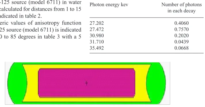
I-125 source (Model 6711)was used in this study to design the source with a silver cylindrical marker (density of 10.5 g/cm3, length of 2.8 mm and a radius of 0.254mm) coating with a combination of bromide Iodine (density 6.245 g/ cm³ Br5I2with a thickness of 2µm).Effective source length which is under a convex angle of 45 degrees source is 2.8mm. This set is placed in a titanium capsule with a density of 4.54 g/cm3 filling by argon gas (density 1.784mg/cm³) and the end is limited with a hemisphere (Figure 1). The average energy of I-125source equals to 28.37 kev and its half-life is 59.4 days 11.
Photon spectrum of I-125 source used in this study according to AAPM TG-43 that is shown in Table 1 (6).
B a s e d o n t h e A A P M , T G 4 3
recommendations6, the dose rate at a certain point, (r, ), relative to the center of the source, D (r, q), is obtained by the following equation:
(1) ) , ( ) ( ) , ( ) , ( ) , ( 0 0 . q q q
q g r F r
r G r G S r
D = kL
wherer is the radial distance from the center source, is polar angle between r and the axis of the source, Sk is air kerma power, E is dose rate constant, G (r, ) is geometric function of spatial dose distribution, F (r, ) is anisotropy function for dosespatial distribution in different angles and radiuses and g (r) is dose radial function of the distance perpendicular to the axis of the source. Point (r0, 0) is the reference of point (r0 = 1 cm, ¸0 = / 2) and is considered for dose calculations.
To calculate the air kerma power of the source, first the air kerma rateK⋅ (d) was
calculated at different distances (5 to 100cm), in a dry air phantom and multiplied by the square of the distance (d2); which result is as follow:
2
). (d d K Sk
⋅
= (9, 12) ...(2)
In order to calculate dose radial function, radioactive source is centering in a cylindrical phantom containing water, and concentric rings with different thicknesses (thickness increase according to increasing the radial distance) are positioned around it3. rings are set to 0.05 thicknesses in distances less than 0.03 cm to source center,0.1 thicknesses in 0.03 to 1 cm distances,0.5 thicknesses for distance between 1cm to 0.03 and 1 cm thickness for distances more than 10 cm. The dose radial function is calculated by the following equation3, 12-15.
k S r D(0, 0)/
. q =
L ...(5)
one of the dosimetric parameters for cylindrical source is anisotropy function. Considering the cylindrical geometry of the sources, being aware of the dose distribution at different angles and radiuses relative to the axis of the source, is important to accurately estimate the dose.To obtain this parameter, radioactive source was placed in the center of a 30 × 30 × 30 cm3 phantom containing water and the anisotropy dose function at a certain point of (r, ) was calculated by placing the radioactive source at various angles and distances using spheres with radius of 0.05cm and its center at the point of (r, )
( , ) ( , ) ) , ( ) , ( ) , (
0 .
0 .
q q
q q
q
r G r D
r G r D r
F =
...(5)
results
The air kerma power of the I-125 source (model 6711) per activity unit was calculated by averaging air kerma power from source at 10cm distance: SK=0.557 cGycm2h-1mCi-1. To calculate this parameter specified produced X-ray from titanium shield was considered.
Dose rate constant, E, was calculated cGyh-1u-10.885, based on the results from Mont Carlo and applying Eq. 3.
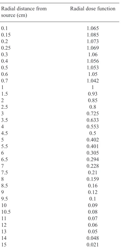
Numeric values of dose geometric function for I-125 source (model 6711) in water phantom was calculated for distances from 1 to 15 cm which is indicated in table 2.
Numeric values of anisotropy function F(r,) for I-125 source (model 6711) is indicated for angles of 0 to 85 degrees in table 3 with a 5
table 1. Photon spectrum I-125, according to AAPM, TG-43
Photon energy kev Number of photons in each decay
27.202 0.4060
27.472 0.7570
30.980 0.2020
31.710 0.0439
35.492 0.0668
degree difference and at distances of 1 to 10 cm.
discussion
Considering the generated specified X-ray from the titanium shield source, air kerma power of I-125 source (Model 6711) per activity unit equals to 0.557 cGycm2h-1mCi-1.Air kerma power of I-125 source (model 6711) considering produced X-ray from source capsule was reported 0.557 cGycm2h-1mCi-1, by rodriguez et al.(2005) in evaluating Penelope code for low energy sources, which exactly equal to the results of the present study3.
According to the mentioned study, ignoring the lack of specified X-ray can lead to unacceptable error inair kerma calculation, because in this situation,calculated air kerma power is 0.679 cGycm2h-1mCi-1, indicating 22% reduction in air kermapower.
Accordingly, as recommended in the revised standard by NIST, all old data related to air kerma, especially in terms of low-energy sources must be revised in order to considering the impact of producing specified X-ray in capsule source. however hedtjarn et al. (2000), reported 2 to 3% increase in source I-125 (model 6702) taking into consideration the revised factors recommended by NIST17.
curve 2. Anisotropy functions for I-125source (Model 6711), different radial distances from different angles comparing to other results
curve1. radial dose values for I-125 source compared to rivard et al (2009) (6) and rodriguez et al (2005) (2). a) radial distance to 15 cm, b) radial distance to 1 cm
Compared to other studies,air kermapower produced in this study indicates more compatibility with reported value by rivard et al (2005)11. Alsodose rateconstant, E, for I-125 source (model 6711) was evaluated cGyh-1u-1 885/0 which was compatible with reported data compared to other values reported in table 4 3,11,18.
Data related to radial dose function are indicated in figure 2. Assuming linearity of the source, radial function has been calculated by geometric functions. As seen in Curve 1, radial dose function indicate more compatibility with data reported by rivard et al. (2009)11, rather than radial dose function presented by rodriguez et al. (2005)3.
This compatibility works well particularly in more radial distances (>8cm) and also less distances (<1cm), however calculation errors are increased upto %5, due to photonic flux reduction; a part of this difference is related to
different interaction between cross section level applied between Penelope code which was used by rodriguez et al. (2005) by means of mcnpx (2.6.0) code in this study3.
table 3. Numeric values of anisotropy function F(r,¸) for I-125 source (model 6711)
radial Angle(degree) distance (cm) 5 4 3 2
0.565 0.512 0.488 0.31 5 0.597 0.641 0.531 0.43 10 0.623 0.676 0.593 0.62 15 0.702 0.746 0.672 0.73 20 0.781 0.792 0.74 0.75 25 0.827 0.835 0.799 0.85 30 0.922 0.901 0.851 0.9 40 0.935 0.955 0.918 1.03 50 0.978 0.985 0.959 1.05 60 0.998 1.02 0.999 1.04 70 1.066 1.05 1.03 1.03 75 1.075 1.06 1.023 1.03 80 1.056 1.05 1.026 1.02 85
table 4. Dose rate constant for I-125 source (Model 6711) compared with other researches results
reference name Source Model E(cGyh-1u-1)
rivard(2009) (6) 6711 0.904 rodriguez (2005) (2) 6711 0.867 Mainegra (1998) (12) 6711 0.81 Current research 6711 0.887 table 2. Geometric dose function
for I-125 source (model 6711)
radial distance from radial dose function source (cm)
0.1 1.065
0.15 1.085
0.2 1.073
0.25 1.069
0.3 1.06
0.4 1.056
0.5 1.053
0.6 1.05
0.7 1.042
1 1
1.5 0.93
2 0.85
2.5 0.8
3 0.725
3.5 0.633
4 0.553
4.5 0.5
5 0.402
5.5 0.401
6 0.305
6.5 0.294
7 0.228
7.5 0.21
8 0.159
8.5 0.16
9 0.12
9.5 0.1
10 0.09
10.5 0.08
11 0.07
12 0.06
13 0.05
14 0.048
15 0.021
Anisotropy dose functions F (r, q), I-125 source (Model 6711) with the assumption of dose linearity compared to rivard et al. (2009) (11) and rodriguez et al. (2005)3 are indicated for different distances in Curve2 (a-d). Calculated anisotropy functions for I-125 source (Model 6711) in this study respectively indicate 0.32% and 0.24%, 4.3%, and 8.4%, 2.7% and 8.1% difference for radial distances of 2, 3, 4cm compared to results by rivard et al.(2009)11 and rodriguez et al. (2005)3.
2.3% and 4.7% difference was obtained
for radial distance of r= 5 in angle distances of 0 to 90 degree compared to results by rivard et al. (2009)11 and rodriguez et al. (2005) 3, however the difference decreases with increasing the angle relative to the axis of the source. This suggests that with increasing the distance, various factors of the difference (mentioned in radial dose function section), have less impact on absorbed dose.
According to proposed AAPM, TG-43protocol6, knowing the desired anisotropy dose functions F (r, q) in every angle relative to perpendicular axis to the central axis in different radial distances from source center is essential to calculate the dose in brachytherapy treatment systems using Eq. 1. Demonstration these data in form of mathematical equations, can provide an easier access to the information provided.
equation and correlation coefficient of 0.9939 for radial distance of 5 cm as F(r, q)=-3e-09q5 +6e-07q4-4e-05q3 +.0013q2 -0.0028q + 0.5684. dose rate can be calculated at any point around source I-125 (model 6711),using MCNPX simulation code.
The data can be used to work for treatment designing and writing systems based on Monte Carlo methods. Compared with the applications built solely on mathematics basis, Monte Carlo system, can specify dose distribution for each patient, taking into account the patient’s specific anatomical condition.
conclusion
Air kerma power,Sk, I-125 source (model 6711) per activity unit equals to SK=0.557 cGycm2h-1mCi-1and dose rate constant equals to L=0.887(cGyh-1u-1). obtained equation for radial dose function of I-125 source (model 6711) was estimated r2-0.0970 r+1.0995 g(r)= -.0001r4+0.0026 r3-0.0178by degree 5 equation and regression 0.9989.
Dosimetric parameters stated in The AAPM, TG-43 proposed protocol (6) for brachytherapy source I-125 (model 6711), can be calculated using MCNPX Mont Carlo computational code, considering low radiant energy and extreme dose changes related to distance.
Calculated values for source air kerma power, dose rate constant , radial dose function, g(r), anisotropy functions,f(r, q) can be used in brachytherapy I-125 source(model 6711) and treatment software designing. These data would be also beneficial for advanced treatment planning software based on Mont Carlo in future.
acknowledgMents
This study was performed as a part of a Master thesis at the Department of Medical Physics, Ahvaz Jundishahpur university of Medical Sciences and was financially supported by the research project No.IorC-9201.
reFerences
1. Gearheart DM, Drogin A, Sowards K, Meigooni AS, Ibbott GS. Dosimetric characteristics of a new I brachytherapy source. Medical physics.
2000; 27: 2278.
2. Blasko JC, ragde h, luse rW, Sylvester JE, Cavanagh W, Grimm PD. Should brachytherapy be considereda therapeutic option in localized prostate cancer? urologic Clinics of North America. 1996; 23(4): 633-50.
3. rodríguez EA, Alcón EP, rodriguez Ml, Gutt F, de Almeida E. Dosimetric parameters estimation using PENEloPE Monte-Carlo simulation code: Model 6711 a< sup> 125</sup> I brachytherapy seed. Applied radiation and isotopes. 2005; 63(1): 41-8.
4. russell KJ, Caplan rJ, laramore GE, Burnison CM, Maor Mh, Taylor ME, et al. Photon versus fast neutron external beam radiotherapy in the treatment of locally advanced prostate cancer: results of a randomized prospective trial. International Journal of radiation oncology* Biology* Physics. 1994;28(1):47-54.
5. Weaver K. Anisotropy functions for I-125 and Pd-103 sources. Med Phys. 1998; 25(12):2271-8. 6. rivard MJ, Coursey BM, DeWerd lA, hanson
WF, huq MS, Ibbott GS, et al. update of AAPM Task Group No. 43 report: A revised AAPM protocol for brachytherapy dose calculations.
Medical physics. 2004;31: 633.
7. rivard MJ, Wierzbicki JG, Van den heuvel F, Martin rC, McMahon rr. Clinical brachytherapy with neutron emitting Cf sources and adherence to AAPM TG-43 dosimetry protocol. Medical physics. 1999; 26: 87.
8. Das PK, Keleti D, Zhu Y, Kirov AS, Meigooni AS, Williamson JF. Validation of Monte Carlo dose calculations near<sup> 125</sup> I sources in the presence of bounded heterogeneities.
International Journal of Radiation Oncology* Biology* Physics. 1997; 38(4): 843-53. 9. Awan SB, Dini SA, hussain M, Meigooni DS,
Meigooni AS. Cylindrical coordinate based TG-43u1 parameters for dose calculation around elongated brachytherapy sources. Journal of Applied Clinical Medical Physics. 2008; 9(2). 10. Walter lS. lANl (los Alamos National
laboratory) Monte Carlo N-Particle transport code system for multiparticle and high energy applications. Version 240, : Los Alamos National Laboratory; 2002.
11. rivard MJ. Monte Carlo radiation dose simulations and dosimetric comparison of the model 6711 and 9011 I-125 brachytherapy sources. Med Phys. 2009; 36(2): 486-91. 12. Sowards KT, MeigooniAS. A Monte Carlo
33.
13. li Z. Monte Carlo calculations of dosimetry parameters of the urocor Prostaseed I source. Medical physics. 2002; 29: 1029.
14. rivard MJ. Comprehensive Monte Carlo calculations of AAPM Task Group report No. 43 dosimetry parameters for the Model 3500 I-125 brachytherapy source. Applied Radiation and Isotopes. 2002; 57(3): 381-9.
15. Ghassoun J, Mostacci D, Molinari V, Jehouani A. Detailed dose distribution prediction of Cf-252 brachytherapy source with boron loading dose
enhancement. Applied Radiation and Isotopes. 2010; 68(2):265-70.
16. Meigooni A. recent developments in brachytherapy source dosimetry. Iran J Radiat Res. 2004; 2(3): 97-105.
17. hedtjärn h, Carlsson GA, Williamson JF. Monte Carlo-aided dosimetry of the symmetra model I25. S06 I, interstitial brachytherapy seed.
Medical physics. 2000; 27: 1076.