1 | P a g e
AN ALGORITHM FOR SENSORLESS POSITION
DETECTIONSYSTEM USING SWITCHED
RELUCTANCE DRIVES
1
Syed Abdur Rauf Magrabi,
2K Praveen Kumar,
3Chatla Veeraiah
1,2,3
Assistant Professor
,Department of Electrical and Electronics Engineering,
Sphoorthy Engineering College, Nadergul (V), Hyderabad. (India)
ABSTRACT
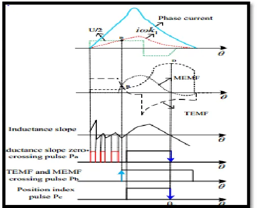
For a switched reluctance motor, it is important to simplify the sensorless control method in medium and high speed operation. A key solution is to detect a single feature position in a single electric cycle. Normally, the aligned position is a typical feature position, which needs to be detected. However, it is difficult to locate the aligned position with the traditional phase inductance slope zero-crossing scheme, especially when the turn-on angle is advanced. In this paper, a transformer electromotive force and motional electromotive force crossing point estimation method is presented, which is combined with the phase inductance slope zero-crossing point estimation method to estimate the aligned position. This method is capable of avoiding the error position index pulses generated at the turn-on position and the regions nearby the unaligned position. Only one position index pulse that represents the aligned position in each electric cycle can be estimated.
Index Terms : Switched Reluctance Motor, Switched Reluctance Motor Drive System, Sensor Less,
MATLAB And PMSM.
I. INTRODUCTION
SRD is an advanced mechatronics device. There are four basic parts in the SRD as shown in Figure l, namely, SRM,
position sensor, power converter and control circuit. The SRM is the key part which outputs the mechanical energy,
and its rotor and stator are both composed by salient poles. The power converter which is the power provider of the
SRM connects the power source to the motor [1].In construction, the SRM is the simplest of all electrical machines.
Only the stator has windings. The rotor contains no conductors or permanent magnets. The steel laminations Stacked
onto a shaft. It is because of this simple mechanical construction that SRMs carry the promise of low cost. The
mechanical simplicity of the device, however, comes with some limitations. As compared to the brushless DC
motor, SRMs cannot run directly from a DC bus or an AC line, but must always be electronically commutated, the
use of commutator is to convert the direct current (DC) to alternating current (AC) and the saliency of the stator and
458 | P a g e
characteristics, complicating the analysis and control of the SRM [1]. This is due to a combination of perceiveddifficulties with the SRM, the lack of commercially available electronics with which to operate them, and the
entrenchment of traditional AC and DC machines in the marketplace. SRMs do, however, offer some advantages
along with potential low cost. For example, they can be very reliable machines since each phase of the SRM is
largely independent physically, magnetically, and electrically from the other motor phases. Also, because of the lack
of conductors or magnets on the rotor, very high speeds can be achieved, relative to comparable motors. Major
problem associated is that they are difficult to control, that they require a shaft position sensor to operate, they tend
to be noisy, and they have more torque ripple than other types of motors; have generally been overcome through a
better understanding of SRM mechanical design and the development of algorithms that can compensate for these
problems. The accuracy of the measured position signal would be seriously affected by the sensors installation.
Besides, the traditional position sensors are vulnerable to the environment temperature, humidity, dust and
electromagnetic interference. A critical solution is to develop sensorless control or self-sensing [2].
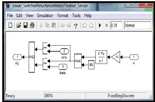
II BLOCK DIAGRAM FOR SRM
The below block diagrams represents the Switched Reluctance Drive based system and an algorithm based drive
system where the power being directly fed to power converter which runs and operates both SRM and current
detector. The purpose of current detector is to limit the flow of current flowing to the control circuitry where the
necessary input parameter been set during this setting period a position sensor is used which senses the speed and
the output power from switched reluctance motor based on this controlling measurements can be done and acts like
a feedback to it. The output is the driving machine or the mechanical energy given out by SRM. The switched
reluctance motor drive (SRD) system not only maintains the simple structure, rugged and reliable benefits of
asynchronous motor, anda good controllability of DC motor, but also has the low price, high efficiency and
adaptability, etc. It has broad prospects, so it is more beneficial to take SRM into wide use for electric drive, forklift
and elevators. Using DSP to control switch reluctance motor drive for electric forklift is bound to promote the
development of electric drive, forklift and elevators [2].
459 | P a g e
Figure 2: shows an algorithm for sensor-less SR drive system.
III OPERATION AND DESIGN ANALYSIS
The magnetic saturation ion of the SRM is relational to the field winding and the position of the stator and the rotor,
so the design of the SRM must use the numerical calculation method like the finite element method (FEM), the
conventionalmagnetic circuit method is not effective. The numerical calculation method has been used in
theapplication for static performance of the SRM. The current controlled mode can be achieved by stand still the
speed of motor up to about 3000 rpm, the motor's electromotive force (emf) is low and the current can be regulated
to the reference value. In this operation mode, the average value of the developed torque is approximately
proportional to the current reference. In addition to the torque ripple due to phase transitions, we note also the torque
ripple created by the switching of the hysteresis regulator. They remain closed during their active periods and the
constant DC supply voltage is continuously applied to the phase windings. This results in linear varying flux
waveforms as shown on the scope. In voltage-fed mode, the SRM develops its 'natural' characteristic in which the
average value of the developed torque is inversely proportional to the motor speed.
460 | P a g e
In SRM drives, both the average torque and torque ripple are affected by the turn-on and turn-off angles and by thecurrent waveforms in the motor phases. And these characteristics change as a function of the motor speed. In many
applications, electric vehicle drives for instance; it is highly desirable to have highest torque/ampere ratio and lowest
torque ripple and this over a widest speed range possible. In the magnetization characteristics of DC shunt generator
the speed is controlled by rheostats/ variable resistances at the average values of voltages and to calculate the critical
speed, critical resistance but whereas in the case of SRD to obtain a non-linear characteristics of magnetization a
freewheeling diode is used which tries limit the high starting of current to the AC-motor along with IGBT used
which triggers voltage at required intervals of time (time ON and time OFF) at different angles but the drawback of
using this it slow down the speed during starting of the motor[8]. The difference in the momentum may also change
the direction of currents is reversed due to the magnetic reversals in the field poles.
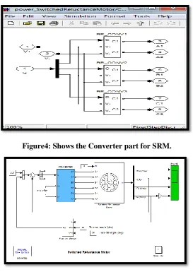
Figure4: Shows the Converter part for SRM.
Figure 5: Shows the block diagram for SRM using MATLAB/SIMULINK.
The above MATLAB based block diagram consists of current-controlled 60-kW 6/4 SRM drive using the SRM
461 | P a g e
converter having three legs, each of which consists of two IGBTs and two free-wheeling diodes. Electric motor iskey part in electric vehicles of traction motors for EV should be as follows, high power including hybrid electric
vehicle, fuel cell electric vehicle and torque density, extended speed range, high efficiency battery electric vehicle.
Wide torque-speed range and high reliability are needed of the motor applied in electric vehicles. Over whole work
area, shockproof, waterproof [6]. It is dustproof. Sensors less motor are fit for the application. Flux strengthening
and weakening control give large maximum efficiency map of the electric machinery applied on EV-torque and high
speed to the motor drives. They are and HEV are important items in power assembly test. The implemented by only
simply controlling the magnitude and electric machinery will help to start the engine or the direction of the current
in an additional coil in the motor. Rotor position is detected by the signal from stationary coils in the vehicle, assist
to drive the vehicle, charge the battery and motor and rotor speed is calculated according to this signal. To absorb
the braking power or sometimes back the vehicle test characteristics of the motor drives, an experimental bench is so
the electric machinery often works in both motor and developed. It is easy to test four quadrants torque-speed and
dynamic characteristics of the motor drives. The whole testing generator mode, and sometimes run both forward and
system is energy saving [6].The SRM torque has a very high torque ripple component which is due to the transitions
of the currents from one phase to the following one. This torque ripple is a particular characteristic of the SRM and
it depends mainly on the converter s turn-on and turn-off angles. In observing the drive's waveforms, we can remark
that the SRM operation speed range can be divided into two regions according to the converter operating mode:
current-controlled and voltage-fed [3].
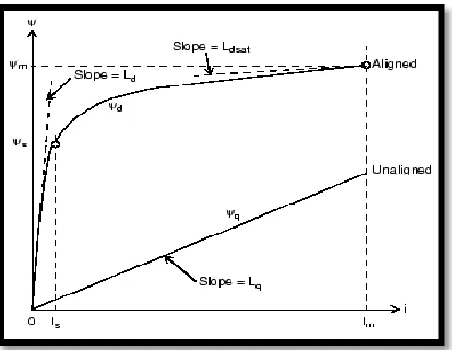
Figure 6: Shows the relationship between flux and current.
The SRM is started by applying the step reference to the regulator input. The acceleration rate depends on the load
characteristics. To shorten the starting time, a very light load was chosen. Since only the currents are controlled, the
462 | P a g e
Figure 7: Shows the aligned position of sensorless drive system.
IV COMPARISON BETWEEN SRM AND PMSM
In this research, Switched Reluctance Motor (SRM) is observed as rare earth free motor. SRM has salient poles
structure according to the electromagnetic steel in rotor and stator. This SRD motors are robust and easier to
compact, the drive under special environment, such as high temperature. SRM is driving by using the torque
generated by change of magnetic reluctance. Therefore, the nonlinearity of current and torque characteristics are
strong. Moreover, torque ripple is large, in order to switch magnetization of motor by the winding of phase. Since it
is necessary to take air gap narrowly, big power occurs to a radial direction. So it is a large vibration and noise. It is
pulse drive like a stepping motor; therefore it is possible to high speed drive easily by making frequency high.
Torque-inertia ratio of SRD of a machine is high, its controllability using feedback looping system gives accurate
analysis of voltage, current, amount of power dissipated and speed response is good [4].
V LOW-NOISE AND LOW-VIBRATION DESIGN
SRM's noise and vibration problem is one of the most controversial issues, even though it has great progress in the
research of eliminating noise and vibration currently, by making improvements in the motor structure or the control
method. But the vibration and noise of the SRM is currently the biggest obstacle for which the SRM isn't used in
Electric Vehicles (EV). So the holistic research on the noise and vibration is necessarycurrently.The
SRMinstantaneous torque control is the most effective means toreduce the SRM torque ripple and noise and
improve thedynamic performance of SRM. But the further research on thetheory and applications about SRM should
be made currently.The SRD's development is closely related to someadvanced technologies which include computer
463 | P a g e
VI CONCLUSIONS
This paper described the research area for SRD motors for operation and sensorless control, theoutput of SRD can
be proportional to the square of the current. At drive constant velocity and high torque, the linkage flux Ψ is
saturated. Since, the iron loss Pi to generate becomes fixed from a certain output. Furthermore, it was able to acquire
good characteristics from few generating of the induction voltage at velocity about the high power range. An equal
output is in as compared with same size PMSM for the test SRM possible in spite of not using the permanent
magnet. However, it is difficult that torque ripple is large and controllability is low still applied. It is necessary to
solve these problems from now on. The SRM has made a very impressive achievement in ashort span of about
twenty years. But the SRD still has a largegap either in theoretical research or in the engineeringapplication by
compared with the DC motor and AC motor-drive systems. There are some main questions impeding thefurther
development and popularity of the SRD, which need tobe researched deeply in the following areas. This research
work can furthermore include control of SRM using Texas Instruments which mainly provides reliability,
controllability for different types of controllers [2]. Mechatronics design theory on SRM, all parts of theSRM have
been studied fastidiously without considering theentire system.The rotor positioninformation is an important
guarantee for reliable operation of the SRM. At present, the photoelectric sensor is used toprovide rotor position
information as its simple structure, butits existence would reduce the reliability of the SRM [1]. So the sensor less
control technology is an attractive control strategy.Especially, the sensor less control of the improved SRM needto
be studied attentively the different structure from theconventional SRM. Some feature characteristics is described in
below:
1) The integration capability with the low speed algorithms: The proposed method is single electric cycle single
reference position estimation based sensorless method.
The precondition of applying this scheme is that the rotational speed in an arbitrary estimation cycle can be deemed
as constant value and an initial reference position should be provided. Thus, for full speed sensorless operation, a
sensorless starting scheme should be added for starting the SR drive to a certain speed and providing the initial
reference aligned position. Actually, the pulse injection based sensorless starting methods such as the current double
thresholds; the peak value of the injected current with the two low/high current references, the direct drive signals,
reference positions and the rotor speed can be obtained. The estimated phase current slope differences of each phase,
the fixed drive signal and the rotational speed can be estimated. These pulse injection based starting schemes are
capable of starting the SRM and maintain sensorless low speed operation. The reference position and rotational
speed, the aligned position of each phase can be obtained which can be used as the initial reference aligned position.
Thus, based on the initial estimated rotational speed and the initial reference aligned position, the proposed method
is capable of integrating with the pulse injection based sensorless starting schemes [2].
2) Magnetic saturation effects: Normally, for medium-high speed operation, the SRM is controlled under APC
mode without current chopping. Single-pulse phase current will increase to its maximum value at the position and
464 | P a g e
effects, the phase inductance would be decreased with the increasing of phase current. It's worth noting that thesaturation effects in the lower
Inductance zone nearby the unaligned position can be neglected. Thus, the saturation factors will not affect the
calculation of the reference motional potential. When the rotor rotates over the initial position of the stator-pole and
the rotor-pole, the saturation effects should be taken into consideration. Inductance will increase according to the
decreasing of the phase current value. When the phase current is lower than the saturation current, the calculated
inductance will overlap with the unsaturated inductance. From this point of view, the calculated phase inductance
slope would be kept positive even under saturation conditions, and thus the aligned position estimation will not be
affected [7].
3) The fault-tolerant capability: According to the basic principle of the proposed method, the estimation of the
aligned position of each phase is completely independent. Thus, the detected position index pulses of each phase can
be used as a redundant backup for real-time rotor position estimation, which provides necessary redundancy and
dependability for sensorless control operation. Therefore, under current/voltage sensor failure conditions or phase
lacking fault conditions, the SR drive system has potential to sustain the failure operation state and possesses fault
tolerant capability [9].
REFERENCES
[1] Syed Abdur Rauf Magrabi, N Deepa (2016) ―Research Study on Switched Reluctance Drives using MATLAB‖
International Journal of Electrical Machines and Drives.
[2] J. Cai, Z Deng (2016) ―A Joint Feature Position detection based sensorless position estimation scheme for
SRM‖ IEEE Transactions on Industrial Electronics.
[3] Zhu Y, Wang D, Zhao G, Yang D, and Wang Y (2009) 'Research Progress of Switched ReluctanceMotor Drive
System'. Proceedings ofthe 2009 IEEEInternational Conference on Mechatronics and Automation
[4] Texas Instruments (2000) Switched Reluctance Motor Control – Basic Operation and Example Using the
TMS320F240 http://www.ti.com/lit/an/spra420a/spra420a.pdf
[5] Wu X, De-an Z, Minggong H, Jianzhang H (2010) 'Research on Switched Reluctance Motor Drive Systemfor
the Electric Forklift Based on DSP and uC/OS'. 2010 International Conference on Electrical and Control
Engineering 4132
[6] Jie L, Hexu S, Shurui F, Yi L (2010) 'Switched Reluctance Motor's Magnetic Force Analysis and the Drive
SystemSimulation Verification'. 2010 2nd International Conference on Industrial and Information Systems 210
[7] Tomoya Ishikawa, Hideo Dohmeki (2012) 'The Fundamental Design Technique ofSwitched Reluctance
Motors,and Comparison with PMSM'. Conference in Electrical Engineering, IEEE 500
[8] R Krishnan, Sung Y P, Keunsoo H (2005) 'Theory and Operation of a Four-Quadrant SwitchedReluctance
Motor Drive With a Single ControllableSwitch—The Lowest Cost Four-QuadrantBrushless Motor Drive '.
465 | P a g e
[9] Zhang Q, Cui S, Tian X (2007) 'Hybrid Switched Reluctance MotorApplied in Electric Vehicles'. IEEETransaction on Electric Vehicles 359
[10]CHANG Yan Tai, CHENG K. W. Eric () 'A Simulation Model for a 4 Phase Switched Reluctance Motor
ForPSIM'.
[11]Software tool is MATLAB or MATRIX LABORATORY RA2012.
[12]IEEE Transactions on SRM (1996) https://www.google.com/patents/US5522653