ISSN (Print) : 2320 – 3765 ISSN (Online): 2278 – 8875
I
nternational
J
ournal of
A
dvanced
R
esearch in
E
lectrical,
E
lectronics and
I
nstrumentation
E
ngineering
(An ISO 3297: 2007 Certified Organization)
Vol. 3, Issue 11, November 2014
Controller Design Approach for Stability
Enhancement in Wind Generation systems
T.Ramkumar
1M. Rama Priya*
2Assistant Professor, Dept. of ECE, Jerusalem College of Engineering,Chennai, Tamil Nadu, India1 Assistant Professor, Dept. of ECE, Bharath University, Chennai, Tamil Nadu, India2
* Corresponding Author
ABSTRACT: This paper presents a performance analysis of controller configurations in Wind energy conversion system (WECS), thus by maintaining the stability of the system. System stability is associated with power system faults in a network such as tripping of transmission lines, Three phase Faults and short circuits. To overcome this problems, effective control techniques have been incorporated in the appropriate area to enhance the operation of the system. Simulation results demonstrate that proposed Fuzzy configuration is better than that of PI configuration in order to stabilize the Self excited wind generator.
KEYWORDS: Wind energy conversion system(WECS), Self excited wind generator, Stability, Transmission Lines,Intelligent Controller.
I. INTRODUCTION
Generation of Electricity through wind received remarkable attention all over the world. Induction Generators are most widely used in Wind energy conversion systems, since they are reliable, robust and cost effective, also it has disadvantages like stability problems[1][3], unsatisfactory voltage and frequency regulation with variation in load. so its essential to analyse the transient stability of wind power stations.
This paper proposes PI-PI and Fuzzy-Fuzzy configuration for the stabilization of grid-connected wind generators. The control scheme is based on the PWM Voltage source converter and a two quadrant dc-dc chopper with IGBT switches.The power flow in and out of the storage coil is determined by the fuzzy controller in response to the undesirable transient faults in the system.The charge and discharge of energy storage coil are determined by the chopper duty cycle, which is controlled by the fuzzy logic. The electrical load is continuously varying by nature so there is need to maintain the stability of the system.In the literature many papers have been developed to control the SEIG using PWM converters. It has been a tendency to operate ac/dc converters with pulse width modulated switching patterns to improve the input and output performance of the converter, the majority of them is concerned with voltage regulation[5]. The difficulty in controlling the converters is mainly due to non-linearity, to overcome the nonlinearity the simplest way is to use conventional controllers. In this paper Intelligent fuzzy controller[7] is implemented ,which is compared and analysed with PI-PI configuration yields the better results than the former.
II.
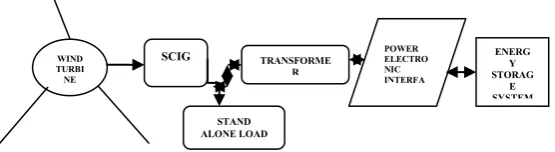
MODEL SYSTEMThe model system, as shown in fig.1,has been used for simulation work.
Figure 1 system model
SCIG WIND
TURBI NE
TRANSFORME R
POWER ELECTRO NIC INTERFA CE
ENERG Y STORAG
E SYSTEM
S STAND
ISSN (Print) : 2320 – 3765 ISSN (Online): 2278 – 8875
I
nternational
J
ournal of
A
dvanced
R
esearch in
E
lectrical,
E
lectronics and
I
nstrumentation
E
ngineering
(An ISO 3297: 2007 Certified Organization)
Vol. 3, Issue 11, November 2014
It consists of one squirrel cage induction generator which delivers power to a bus through transmission line. Capacitance value is chosen such that the power factor of the wind power station becomes unity, when it is generating the rated power. The Induction generator parameters are shown in Table I
TABLE 1 GENERATOR PARAMETERS
III.
M
ODELLING OFPOWER
ELECTRONIC
INTERFACE
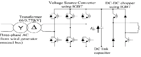
The power electronic interface comprises of three phase voltage source inverter and type-D chopper[8].
A.MODELLING OF VOLTAGE SOURCE CONVERTER AND TYPE-D DC-DC CHOPPER
Figure 2 VSC-Chopper setup A three-phase converter has three load-phase terminals.
The current supplied by the dc bus to the inverter switches is referred as dc link current and the magnitude of dc link current often changes in step (and some times its direction also changes) as the inverter switches are turned on and off. The step change in instantaneous dc link current occurs even if the ac load at the inverter output is drawing steady power. However, average magnitude of the dc link current remains positive if net power-flow is from dc bus to ac load. [1]
The net power-flow direction reverses if the ac load connected to the inverter is regenerating. Under regeneration, the mean magnitude of dc link current is negative . The dc link capacitor should be put very close to the switches so that it provides a low impedance path to the high frequency component of the switch currents[2]
The voltage source converter gets its input voltage 0.77kv from the step down transformer. It acts as a bidirectional converter feeding two quadrant chopper through DC link capacitor,the voltage across the capacitor is maintained constant. If there is any fault in the line,the power returns in the reverse manner.
MVA 50 R1[pu] 0.01 X1[pu] 0.18 Xmu[pu] 10
R2[pu] 0.015 X2[pu] 0.12
ISSN (Print) : 2320 – 3765 ISSN (Online): 2278 – 8875
I
nternational
J
ournal of
A
dvanced
R
esearch in
E
lectrical,
E
lectronics and
I
nstrumentation
E
ngineering
(An ISO 3297: 2007 Certified Organization)
Vol. 3, Issue 11, November 2014
The voltage equation is given by
(15)
Where,
Vd-voltage across the capacitor f-frequency
L-Self inductance Id-current α-triggering angle
The two quadrant chopper is shown in fig.6
Figure 3 Type-D chopper and its quadrant operation
The circuit diagram of the type D chopper is shown in the above figure. When the two choppers are on the output voltage v0 will be equal to Vs . When v0 = – Vs the two choppers will be off but both the diodes D1 and D2 will start
conducting. V0 the average output voltage will be positive when the choppers turn-on the time Ton will be more than
the turn off time Toff its shown in the wave form below. As the diodes and choppers conduct current only in one
direction the direction of load current will be always positive.[2]
The power flows from source to load as the average values of both v0 and i0 is positive. From the wave form it is
seen that the average value of V0 is positive thus the forth quadrant operation of type D chopper is obtained.[3]
From the wave forms the Average value of output voltage is given by
V0= (Vs Ton-VsToff)/T
= Vs.(Ton-Toff)/T (16)
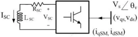
B.ENERGY STORAGE SYSTEM
The energy storage system consists of SMES device. A SMES device is a dc current device that stores energy in the magnetic field. The dc current flowing through a superconducting wire in a large magnet creates the magnetic field. Generally it consists of the superconducting coil, the cryogenic system, and the Power Conversion/Conditioning System (PCS) with control and protection functions
Figure 4 Schematic of energy storage coil
ISSN (Print) : 2320 – 3765 ISSN (Online): 2278 – 8875
I
nternational
J
ournal of
A
dvanced
R
esearch in
E
lectrical,
E
lectronics and
I
nstrumentation
E
ngineering
(An ISO 3297: 2007 Certified Organization)
Vol. 3, Issue 11, November 2014
𝑃
𝑠𝑚= 𝑉
𝑑𝑠𝐼
𝑑𝑠𝑚+ 𝑉
𝑞𝑠𝐼
𝑞𝑠𝑚= 𝑚1|Vs||Isc|cos
α
C
(17)The energy stored in the coil is given by[4][7]
𝐸 =
12
𝐿𝑠𝑚𝐼𝑠𝑚
2
𝑃 =
𝑑𝐸𝑑𝑡
= 𝐿𝑠𝑚𝐼𝑠𝑚
𝑑𝑖𝑠𝑚
𝑑𝑡 (18)
= 𝑉𝑠𝑚𝐼𝑠𝑚
(19) Vs= (𝑉𝑞𝑠2+ 𝑉𝑑𝑠2) (20)Where
𝑃
𝑠𝑚-Power in the coil.Vds,, Vqs,-d-q axis voltage.
Lsm-Inductance of the coil Ism-current flows through the coil Isc-Short circuit current
αC-angle between the voltages m1-duty cycle
IV.
PROPOSED SYSTEM
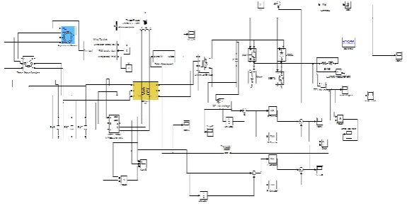
A.PI-PI CONFIGURATION
In this configuration the PI controllers are used to control the firing pulses for voltage source converters as well as the duty cycle of type-D chopper as shown in figure.7
The PI controller is tuned by the traditional Ziegler-nichols method. After tuning, the values of proportional, integral gains were obtained. Effective rigorous tuning methods yields optimum values. [4]
Figure 5 Simulink model for PI-PI configuration
When single phase open circuit fault is applied the energy stored in the coil maintains the voltage and power in B phase under fault time.[5]
ISSN (Print) : 2320 – 3765 ISSN (Online): 2278 – 8875
I
nternational
J
ournal of
A
dvanced
R
esearch in
E
lectrical,
E
lectronics and
I
nstrumentation
E
ngineering
(An ISO 3297: 2007 Certified Organization)
Vol. 3, Issue 11, November 2014
of the integral mode the stability of the control loop is decreased.[6] Extreme caution should be used in applying this controller to process transfer functions containing I/s terms[6].
(21) Where, Kp-proportional gain
Ki-integral gain E(t)-error
U(t)-controller output
The output voltages, current and power waveforms of the IG after applying single phase open circuit fault to B phase between 0.033 to 0.067 seconds are shown in fig.9
It can be clearly seen that, after the fault get cleared, the power and voltage doesn’t regain to its original operating point. The power shoots through and settles down. This may cause unwanted disturbances in the load.[7]
Figure 6 Output waveforms of PI-PI configuration
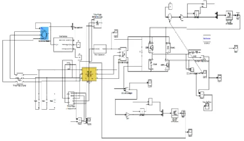
B.FUZZY-FUZZY CONFIGURATION
Figure 7 Simulink model of fuzzy-fuzzy configuration Fuzzy rules
The rules included in fuzzy technique for chopper and voltage source converter is shown in table 1 and 2.
In fuzzy-fuzzy configuration the controller generates appropriate firing signals as well as duty ratio for chopper . [8] The output voltages, current and power waveforms of the IG after applying single phase open circuit fault to B phase between 0.033 to 0.067 seconds are shown in fig.15
Time(Seconds) Voltage
(Volts)
Current (Amperes)
Power (Watts)
ISSN (Print) : 2320 – 3765 ISSN (Online): 2278 – 8875
I
nternational
J
ournal of
A
dvanced
R
esearch in
E
lectrical,
E
lectronics and
I
nstrumentation
E
ngineering
(An ISO 3297: 2007 Certified Organization)
Vol. 3, Issue 11, November 2014
Figure 8 Output waveforms of Fuzzy-fuzzy configuration
Figure 9 GUI Development of fuzzy rules Table 2 Fuzzy rules for SMES control through chopper
Change in power across the coil
Duty cycle
NB VERY SMALL NS SMALL
Z MEDIUM PS BIG PB VERY BIG Table 3 Fuzzy Rules for Voltage source converter
Change in power across the coil
Duty cycle
NB VERY SMALL NS SMALL
Z MEDIUM PS BIG PB VERY BIG
Fig.11 shows the curves of output voltages, currents and power of SCIG after opening circuit breaker at 0.0333 sec to 0.067 sec and Fuzzy controller maintains voltage and power. [9]
Time (Seconds)
Voltage (Volts)
Current (Amperes)
ISSN (Print) : 2320 – 3765 ISSN (Online): 2278 – 8875
I
nternational
J
ournal of
A
dvanced
R
esearch in
E
lectrical,
E
lectronics and
I
nstrumentation
E
ngineering
(An ISO 3297: 2007 Certified Organization)
Vol. 3, Issue 11, November 2014
Compared to PI controller it has much improved performance and without distortions in O/P waveforms. After the faults get cleared at 0.067 sec immediately the voltage, current and Power gets settled without any deviations.[10] In the case of SMES with Fuzzy configuration, the power regaining is very much sooner and performance is healthier than the configuration having PI controller
.
V. COMPARISON BASED ON SIMULATION RESULTS
I t can be inferred that, when fuzzy controller is incorporated either to control DC link voltage or to control the SMES voltage, the results depicts that output voltage and power has a quicker regaining compared to PI-PI configuration.[11]
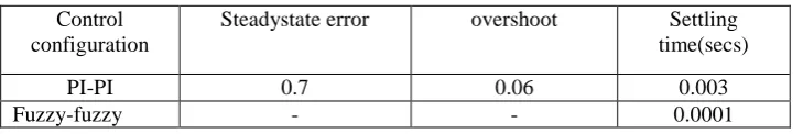
Moreover, the Fuzzy-Fuzzy configuration yields better performance parameters than PI-PI configuration, so it is compared with it which is shown in table 3 with respect to output voltage.[12]
Table 4 Comparison of Controller parameters Control
configuration
Steadystate error overshoot Settling time(secs) PI-PI 0.7 0.06 0.003 Fuzzy-fuzzy - - 0.0001
It shows that there is no steady state error, overshoot in Fuzzy-Fuzzy configuration[13]. Thus fuzzy Configuration along with SMES is invoked, then the output voltages and power were balanced sinusoidally and settles down to normal values in a very less time compared to PI-PI configuration. [14]
VI. CONCLUSION AND FUTURE WORK
Thus the proposed fuzzy logic controlled system has a better stability to fault conditions than the
PI-PI configuration. Thus fuzzy Configuration along with SMES is invoked, then the output voltages and power were balanced and settles down to normal values in very less time compared to PI-PI configuration. The effective tuning of Fuzzy controller by adding more number of rules in order to stabilize the fixed speed WECS under various short circuit faults and This proposed model is to be interfaced with grid so that various stability problems can be analysed in futureREFERENCES
1. Frede Blaabjerg, Marco Liserre,IEEE, and Kema,”Power Electronics Converters for Wind Turbine Systems”., IEEE Transactions on Industrial Applications., Vol. 48, No. 2, March/April 2012.
2. Krishnamoorthy P., Jayalakshmi T., "Preparation, characterization and synthesis of silver nanoparticles by using phyllanthusniruri for the antimicrobial activity and cytotoxic effects", Journal of Chemical and Pharmaceutical Research, ISSN : 0975 – 7384, 4(11) (2012) pp.4783-4794.
3. Aditya Venkataraman, A. I. Maswood, Nirnaya Sarangan and Ooi H. P. Gabriel,”An Efficient UPF Rectifier for a Stand-Alone Wind Energy Conversion System “., Paper selected for publication in IEEE.
4. Madhubala V., Subhashree A.R., Shanthi B., "Serum carbohydrate deficient transferrin as a sensitive marker in diagnosing alcohol abuse: A case - Control study", Journal of Clinical and Diagnostic Research, ISSN : 0973 - 709X, 7(2) (2013) pp.197-200.
5. Mohd. Hasan Ali, Minwon Park, In-Keun Yu,
Toshiaki Murata and Junji Tamura, “Improvement of wind generator stability by fuzzy logic controlled SMES”., IEEE transactions on industry applications, vol. 45, no. 3, may/june 2009
6. Khanaa V., Thooyamani K.P., Saravanan T., "Simulation of an all optical full adder using optical switch", Indian Journal of Science and Technology, ISSN : 0974-6846, 6(S6)(2013) pp.4733-4736.
7. Mohd. Hasan Ali and Bin Wu, “Comparison of Stabilization Methods for Fixed-Speed Wind Generator Systems”IEEE Transactions on power delivery”.,Vol.25,No.1January 2010.
8. Gaurav Kumar Kasal and Bhim Singh., “Voltage and
Frequency Controllers for an Asynchronous Generator-Based Isolated Wind Energy Conversion System”., IEEE transactions on energy conversion, vol. 26, no. 2, june 2011.
ISSN (Print) : 2320 – 3765 ISSN (Online): 2278 – 8875
I
nternational
J
ournal of
A
dvanced
R
esearch in
E
lectrical,
E
lectronics and
I
nstrumentation
E
ngineering
(An ISO 3297: 2007 Certified Organization)
Vol. 3, Issue 11, November 2014
10. Junji Tamura,”Transient stability stimulation of power system Including wind generator by PSCAD/EMTDC.”,paper accepted for PPT 2001 IEEE Porto powertech conference.,10th to 13th september,porto,portugal.
11. M. Azouz, A. Shaltout and M. A. L. Elshafei, N. Abdel-Rahim, H. Hagras and M. Zaher, M. Ibrahim “Fuzzy Logic Control of Wind Energy Systems” Proceedings of the 14th International Middle East Power Systems Conference (MEPCON’10), Cairo University, Egypt, December 19-21, 2010, Paper ID 311.
12. Bhat V., "A close-up on obturators using magnets: Part I - Magnets in dentistry", Journal of Indian Prosthodontist Society, ISSN : 0972-4052 , 5(3) (2005) pp.114-118.
13. T.Ramkumar and S.G.Bharathi dasan, “Design of SMES control for wind generator stability” International Conference on Circuit, 14. Power and Computing Technologies [ICCPCT’14], NI University, India. Paper Selected for publication in IEEE Digital Library,Paper ID
318.
15. P Thamarai, B Karthik, Automatic Braking and Evasive Steering for Active Pedestrian Safety, Middle-East Journal of Scientific Research 20 (10), PP 1271-1276, 2014.
16. Shriram, Revati; Sundhararajan, M; Daimiwal, Nivedita; , Human Brain Mapping based on COLD Signal Hemodynamic Response and Electrical NeuroimagingarXiv preprint arXiv:1307.4171, 2013. Daimiwal, Nivedita; Sundhararajan, M; Shriram, Revati; , Respiratory rate, heart rate and continuous measurement of BP using PPGIEEE Communications and Signal Processing (ICCSP), 2014 International Conference on, PP 999-1002,2014.
17. Shriram, Revati; Sundhararajan, M; Daimiwal, Nivedita; , Effect of change in intensity of infrared LED on a photoplethysmogramIEEE Communications and Signal Processing (ICCSP), 2014 International Conference on, PP 1064-1067,2014.
18. Daimiwal, Nivedita; Sundhararajan, M; Shriram, Revati; , Comparative analysis of LDR and OPT 101 detectors in reflectance type PPG sensorIEEE Communications and Signal Processing (ICCSP), 2014 International Conference on, PP 1078-1081,2014.