Improved Power Factor Correction for BLDC
Drive Using Fuzzy Logic Controller
P.M.Dhanasekaran1, P.Veena2, R.Jeyabharath3
Research Scholar, Department of EEE, K. S. Rangasamy College of Technology, Tamilnadu, India1
Professor, Department of EEE, KSR Institute for Engineering and Technology, Tamilnadu, India2,3
ABSTRACT: This paper presents a DCM based PFC (Power Factor Correction) based BL (Bridgeless)-Single phase
single ended primary inductance converter (SEPIC) converter fed BLDC (Brushless DC) motor drive. The proposed converter topologies are implemented to provide the near unity power factor in a successful manner. The proposed speed control scheme has the work of DC link voltage control proportional to the desired speed of the BLDC motor. The converter combines the PFC and DC link voltage control and uses a single controller. The bridgeless SEPIC converter topology is used to obtain the low conduction losses and low range of heat sinks for the switches. The proposed system is designed with Fuzzy controller and simulated to operate around a wide range of speed control with near unity power factor at input side. The proposed power factor correction converter limits the harmonic distortion (THD) below 5% of total current at AC mains.
KEYWORDS:BLDC, Bridgeless SEPIC converter, THD, Power factor correction, fuzzy logic controller
I. INTRODUCTION
In recent years BLDC motors are considerably used in a aerospace, Motion control and defence applications such as vehicle tracking, gyroscope, aircraft on swine instrumentation, fuel monitoring position and quick actuators because of their valuable efficiency, high starting torque, reliability, decline maintenance, less chat compared to brushed DC motor [1]. The stator of the BLDCM comprises of three-phase combined windings and rotor has dependable magnets. It is furthermore recognized as an electronically commutated motor (ECM) considering an electric commutation created on rotor position by a three-phase voltage source inverter (VSI) is used [16], [17]. Thus, the problems associated with brushes, one as sparking, and exasperate and roar of the commutator chamber of deputy are excluded. A conventional BLDC motor fed by a Diode bridge rectifier results in total harmonic distortion of supply current in the range of 60% which leads the reduced power factor. The IEC 61000-3-2 standard is recommended for the high power factor and improved power quality at a way with element and gone straight power action at the supply is chosen [18] .Hence an efficient drive system is necessary to give a wide range of speed act with power factor correction and righteous power action at the AC mains at an capable cost.
To overcome these drawbacks, different bridgeless topologies are recommended for step-up/step-down applications have been introduced in [10]–[12]. In [10], three semiconductor switches in the current conduction path during each cycle. In [11], a bridgeless PFC circuit based on the SEPIC topology is presented.
The selection of mode of operation is a tradeoff between the allowed stresses on PFC switch and cost of the around system during the operating mode of front-end converter. The two different modes of operation are depending on design parameters; either continuous or discontinuous conduction mode approach may lead the converter. In this design, a BLDC motor drive fed by a PFC BL-SEPIC operates in four modes. At the time of starting or overloading inrush current is created. The inrush current occurring at start-up or overload was eliminated by operating the PFC in discontinuous conduction mode (DCM), it also gives natural protection for switches, low input ripple, and less electromagnetic interference (EMI) [15]. In this paper a fuzzy controlled BL-SEPIC is analysed in terms of harmonic reduction.
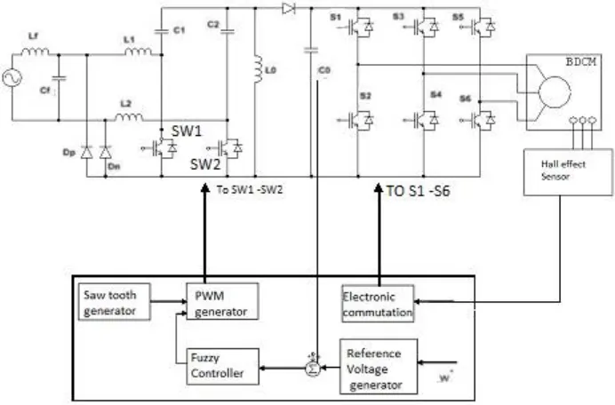
II. PROPOSED PFC BRIDGELESS SEPIC CONVERTER FED BLDC MOTOR DRIVE
The proposed converter consists of four switches and diodes are used in Figure 1. The frontend consists of a SEPIC converter comprised of inductors L1 and L2, typical capacitor C1, diode D1 and turn out capacitor C2. The
changes from the rule SEPIC configuration are the diode D1 is covering in the return path. This is to not allow the flow
of current during the periods of negative emf. A, B, and C are the three windings and the currents on them are controlled by turn on and turn off of the switches SA, SB and SC correspondingly. Single switch per phase is used, so
the currents through them are unidirectional. The diodes DA, DB and DC act as freewheeling diodes to allow the
winding currents to dissipate when the switches are turned off during the process of phase commutation. The output of the converter is used to excite the three phases of the machine, and the voltage of capacitor C1 is used to demagnetize
the phases around turn-off and for current control.
III. SIMULATION RESULTS
The operation of the projected topology has been verified by simulation for MATLAB/SIMULINK. The rotor position is sensed by means of three Hall Effect sensors, and the motor position information is used to determine the phase winding to be excited. The machine speed is derived from the position of inputs and is compared with the speed reference to generate the current references. Fuzzy logic control is used to standardize the phase currents to the reference current. The dc bus voltage is regulated by PWM control of the switch S1. Performances indices such as supply voltage (Vin), supply current (is), DC link voltage (Vdc), speed are analyzed for determining the performance of
proposed BLDCM drive. Power quality indices such as PF (Power Factor), THD (Total Harmonic Distortion) of supply side are analyzed for demonstrating the improved power quality at AC mains.
Figure 2 Fuzzy Logic Controller
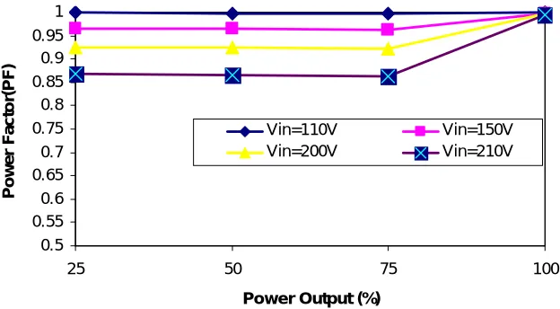
The mamdani fuzzy inference system is implemented with triangular membership functions as input and output variables. The inputs to the Fuzzy controller are voltage error and change in voltage error. The output is the controlling signal given to BL-SEPIC for PFC. Figure 3 shows the source current with 4.37% THD which is according to standard limits. For different input voltages the speed of the BLDC is varied and the power factor is also maintained as shown in Figure 4.
Figure 4 Power factor Vs output for different input
Table1 Performance of the proposed BL-SEPIC PFC drive with Diode Bridge PFC
Parameters
Obtained Values
Without Diode Bridge PFC BL-SEPIC
Power Factor 0.872 0.998
THD 21% 4.35%
Table 1 gives comparative results with conventional Diode Bridge PFC and BL-SEPIC. The parameters compared are power factor and THD. The obtained values after simulation shows the better results for usage of BL-SEPIC PFC compared with conventional PFC circuits.
IV. CONCLUSION
The Simulink model for a BLDC Motor drive system with stator current control by using Simulink blocks has been developed and operated at rated speed. A mathematical expression of the system is simply incorporated in the MATLAB simulation and the usage of numerous appliance boxes and support guides simplifies the simulation of large control system. Simulink is effective of recommending real time results with reduced simulation time process and debugging. Usually in such drive system the inverter is driven by Fuzzy Logic controller. The Simulink simulation allows performance study of BLDC Motor drives with DCM. It is found that the power factor is near unity with the use of BL-SEPIC converter. The efficiency increases due to the increase in the power factor.
0.5 0.55 0.6 0.65 0.7 0.75 0.8 0.85 0.9 0.95 1
25 50 75 100
Power Output (%)
REFERENCES
[1] Huang, X., Goodman, A., Gerada, C.,Fang, Y.,and Lu,Q., “A single sided matrix converter drive for a brushless dc motor in aerospace applications”, IEEE Trans. Ind. Electron., Vol. 59, No. 9, PP. 3542–3552, Sep. 2012.
[2] Ismail, E. H., “Bridgeless SEPIC rectifier with unity power factor and reduced conduction losses”, IEEE Trans. Ind.Electron., Vol. 56, No. 4, PP. 1147–1157, Apr. 2009.
[3] Jang, Y., and Jovanovich, M. M., “A bridgeless PFC boost rectifier with optimized magnetic utilization” , IEEE Trans.Power Electron., Vol. 24, No. 1, PP. 85–93, Jan. 2009.
[4] Nedmohan, “Power Electronics Converters, Applications and Design”, Third Edition, Wiley-India Edition, 2012.
[5] Martinez .R ., and Enjeti, P. N “A high performance single phase rectifier with input power factor correction,” IEEE Transactions on Power Electronics, Vol. 11, No. 2, PP. 311–317, March 1996. .
[6] Jian Sun, “On the Zero-Crossing Distortion in Single-Phase PFC Converters”, IEEE Transactions on Power Electronics, Vol. 19, No. 3,PP 685-692, May 2004.
[7] Wang,J., Dunford, W.G., and Mauch,K., “Analysis of a ripple-free input current boost converter with discontinuous conduction characteristics”, IEEE Transactions on Power Electronics, Vol. 12, No. 4, PP. 684–694, July 1997.
[8] Wuidart,L., “Topologies for Switched Mode Power Supplies” , AN513/0393, 1999.
[9] Mahdavi, M., and Farzanehfard,H., “Bridgeless SEPIC PFC rectifier with reduced components and conduction losses”, IEEE Trans. Ind. Electron.,Vol. 58, No. 9, PP. 4153–4160, Sep. 2011.
[10] Wei,W., Hongpeng,L., Shigong,J., and Dianguo,X., “A novel bridgeless buck-boost PFC converter”, in Proc. IEEE Power Electron. Spec. Conf., 2008, PP. 1304–1308.
[11] Ismail, E. H., “Bridgeless SEPIC rectifier with unity power factor and reduced conduction losses”, IEEE Trans. Ind. Electron., Vol. 56, No. 4,PP. 1147–1157, Apr. 2009.
[12] Sabzali.,Ismail, E.H., Al-Saffar, M., and Fardoun,A., “New bridgeless DCM sepic and Cuk PFC rectifiers with low conduction and switching losses”, IEEE Trans. Ind. Appl., Vol. 47, No. 2, PP. 873–881, Mar./Apr. 2011.
[13] Huber,L.,Gang, L., and Jovanovic, M. M., “Design-oriented analysis and performance evaluation of buck PFC front-end”, IEEE Trans. Power Electron., Vol. 25, No. 1, PP. 85–94, Jan. 2010.
[14] Jang, Y., and Jovanovi´c,M.M., “Bridgeless high-power-factor buck converter”, IEEE Trans. Power Electron., Vol. 26, No. 2, PP. 602–611, Feb.2011.
[15] Simonetti, D. S. L., Sebastian, J., and Uceda, J., “The discontinuous conduction mode Sepic and Cuk power factor preregulators: Analysis and design”, IEEE Trans. Ind. Electron., Vol. 44, No. 5, PP. 630–637, Oct. 1997.
[16] Sokira, T. J., and Jaffe, W., “ Brushless DC Motors: Electronic Commutation and Control”. Blue Ridge Summit. PA, USA: TAB Books, 1989. [17] Toliyat, H. A., and Campbell, S., DSP-Based Electromechanical Motion Control. Boca Raton, FL, USA: CRC Press, 2004.
[18] Limits for Harmonic Current Emissions (Equipment input current ≤16 A per phase), International Standard IEC 61000-3-2, 2000
[19] Bist and Singh, B., “An adjustable speed PFC bridgeless buck-boost converter fed BLDC motor drive”, IEEE Trans. Ind. Electron., Vol. 61, No. 6, PP.2665–2677, Jun. 2014.
[20] Singh, B. , and Bist, V. “An improved power quality bridgeless Cuk converter fed BLDC motor drive for air conditioning system”, IET Power Electron., Vol. 6, No. 5, PP. 902–913, 2013.
[21] Singh, B., and Bist, V., “Power quality improvement in PFC bridgeless SEPIC fed BLDC motor drive”, Int. J. Emerg. Elect. Power Syst., Vol. 14,No. 3, PP. 285–296, 2013.