Optimum Design Parameter Estimation of
PID Controller in AVR System using Artificial
Bee Colony Algorithm
Arvind Pande
1, B.S Patil
2, Dr. S.B Patil
3Assistant Professor, Department of Information Technology, PVPIT Engineering College, Sangli, MS, India1 Associate Professor, Department of Information Technology, PVPIT Engineering College, Sangli, MS, India2
Professor, Department of Electronics Engineering, Dr. JJMCOE, Kolhapur, MS, India3
ABSTRACT: In this paper, an artificial intelligence method, artificial bee colony Optimization (ABC) algorithm is presented for determining the optimal parameter for proportional-integral-derivative (PID) controller. Proportional-Integral-Derivate (PID) controllers are widely used in industry because of their remarkable efficiency, simple structure and robust performance for a wide range of applications. Parameters tuning ( Kp, Ki, Kd ) of PID controller is necessary to satisfy the operation of the system. But many tuning methods such as Ziegler-Nichols methods do not work as perfectly as it is expected. Such methods have many disadvantages such as lack of precision, long run time and lack of stability. Therefore, artificial bee colony Optimization (ABC) algorithm is applied to system in order to optimize the PID controller parameters and improve the performance of PID controller system. The simulation results show that the ABC method is more effective in improving the step response characteristics such as: overshoot, rise time and settling time.
KEYWORDS
:
ABC, AVR, step response, PID Controller, PSOI. INTRODUCTION
The proportional-integral-derivative derivative (PID) controller has been chosen over other controller because it is simple and having a wide range of robust performance. Proportional Integral Derivative (PID) controllers are widely used in industrial applications even though many new control techniques have been proposed [1]. The reason is that it has a simple structure which is easy to be understood by the engineers, and under practical conditions, it has been performing more reliably compared to more advanced and complex controllers [3-4]. The main propose of designing a PID controller is to determine the three gains and they are proportional gain (kp ), integral gain (ki ) and derivative gain (kd ) of the controller [2]. However, the three adjustable PID controller parameters should be tuned appropriately [1].
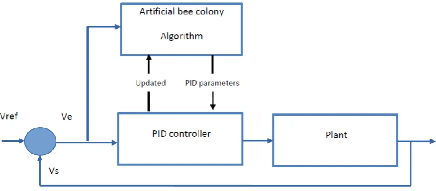
Figure 1 shows design of automatic voltage regulator (AVR) using PID (proportional integration derivative) Controller. Here PID controller parameters are obtained by Artificial Bee Colony optimization algorithm [2].
II. AVR SYSTEM DESIGN USING PID CONTROLLER
The basic function of power system stabilizer is to add damping to the generator rotor oscillations by controlling its excitation using auxiliary stabilizing signal(s). In order to provide damping, the stabilizer will produce electrical torque which minimized the rotor speed deviations. The excitation system is controlled by an automatic voltage regulator (AVR) and a power system stabilizer (PSS).
Figure 1. Block diagram of PID Controller tuning
III. PID CONTROLLER DESIGN FOR AVR SYSTEM
Sr.no Name of model Transfer function Parameter description 1 PID Controller Model
kp is proportion coefficient, kd is differential
coefficient, and ki integral coefficient
2 Amplifier Model
KA is a gain and A is a time
constant
3 Exciter Model
KE is a gain and E is a time
constant
4 Generator Model
KG is a gain and G is a time
constant
5 Sensor Model
KR is a gain and R is a time
constant
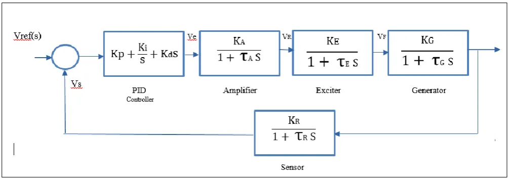
In this paper, the GA and PSO algorithm are applied to search best PID parameters so that the controlled system has a good control performance. The AVR system model controlled by the PID controller can be expressed by Figure 2.
Figure 2: Closed loop block diagram AVR system
In [17] a performance criterion W(K) is defined by
( ) (
This fitness function fG is used in an over-damping system and ITAE is an integral of time multiplied by absolute-error
value.
ITAE = ∑
Where I {0, 1, 2… end time} is an index, ti is the i-th sampling time, and ei is the absolute-error value in the
i-th sampling time.
IV. ARTIFICIAL BEE COLONY ALGORITHM
Artificial bee colony (ABC) is a new population-based stochastic algorithm which has shown good search abilities on many optimization problems. Here this algorithm is used to get the values of kp, ki, kd. This triplet is passed to PID controller which controls AVR. This simulation finds optimized values for kp, ki, kd after multiple feedback iteration from system. The optimized value of above parameter tunes significantly well and suppresses the oscillations in the system and provides good damping characteristics to low frequency oscillations. Hence it stabilizes the system much faster.
In the ABC algorithm, the colony consists of three groups of bees: employed bees, onlookers and scouts. It is assumed that there is only one artificial employed bee for each food source. The number of employed bees in the colony is equal to the number of food sources around the hive. Employed bees go to their food source and come back to hive and dance on this area. The employed bee whose food source has been abandoned becomes a scout and starts to search for finding a new food source. Onlookers watch the dances of employed bees and choose food sources depending on dances.
The main steps of the ABC algorithm are as below.
Initial food sources are produced for all employed bees
REPEAT
o Each employed bee goes to a food source in her memory and determines a neighbor source, then evaluates its nectar amount and dances in the hive
o Each onlooker watches the dance of employed bees and chooses one of their sources depending on the dances, and then goes to that source. After choosing a neighbor around that, she evaluates its nectar amount.
o Abandoned food sources are determined and are replaced with the new food sources discovered by scouts.
o The best food source found so far is registered. UNTIL (requirements are met)
V. SIMULATION RESULTS AND DISCUSSION
The transfer function of the system is:
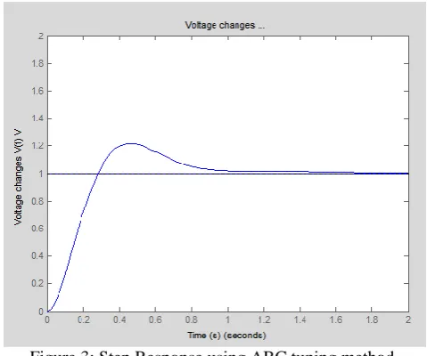
Figure 3 Shows the sample step response of obtained from ABC tuning method for above system transfer function. A PID controller has to be designed such that it improves the following time response parameters.
Figure 3: Step Response using ABC tuning method.
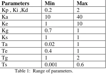
The obtained results has been compared with the conventional Ziegler- Nichols tuning technique& PSO (Particle swarm optimization algorithm) on performance metrics on overshoot (Mp) in%, settling time (Ts), rise time (Tr) and peak time (Tp). Through the simulation results, it is clearly shown that the ABC controller can perform an efficiently and obtain optimal PID controller parameter that can achieve better performance criterion. Following table shows Time response parameters comparisons of obtained using various tuning method. Following table 1 shows searching range for each parameters used in simulation work.
Parameters Min Max
Kp , Ki ,Kd 0.2 2
Ka 10 40
Ke 1 10
Kg 0.7 1
Ks 1 1
Ta 0.02 1
Te 0.4 1
Tg 1 2
Ts 0.001 0.6
Table 1: Range of parameters.
Table 2 shows the results of time response parameter Ts, Tr & Tp for 100 iterations of tuning algorithm. The tuning parameters given by ABC algorithm is Kp =1.9267, Ki= 0.3564, Kd= 0.4094
Sr.no Tuning method Settling time (Ts) Rise Time ( Tr) Peak Time (Tp)
1 Ziegler- Nichols 10.410 0.5110 0.094
2 PSO 5.620 0.4212 0.182
3 ABC 0.268 0.0635 0.150
Table 2: Time response comparisons for 100 iterations.
Table 3 shows the results of time response parameter Ts, Tr & Tp for 200 iterations of tuning algorithm. The tuning parameters given by ABC algorithm is Kp =1.5779, Ki= 0.8408, Kd= 0.7342
Sr.no Tuning method Settling time (Ts) Rise Time ( Tr) Peak Time (Tp)
1 Ziegler- Nichols 6.410 0.5910 0.084
2 PSO 0.2813 0.4021 0.196
3 ABC 0.2501 0.0425 0.095
Table 3: Time response comparisons for 200 iterations.
Table 4 shows the results of time response parameter Ts, Tr & Tp for 300 iterations of tuning algorithm. The tuning parameters given by ABC algorithm is Kp =1.6521, Ki= 0.3896, Kd= 0.5634
Sr.no Tuning method Settling time (Ts) Rise Time ( Tr) Peak Time (Tp)
1 Ziegler- Nichols 8.410 0.6310 0.034
2 PSO 3.740 0.9212 0.292
3 ABC 0.668 0.0235 0.137
Table 4: Time response comparisons for 300 iterations.
VI. CONCLUSION
Simulation results have shown that the control parameters obtained from ABC method gives stable time response parameters which provides more stability and efficiency for AVR. Results also show that searching PID controller parameters is easier and quicker than PSO & Ziegler- Nichols method.
REFERENCES
[1] . ol , “ uzzy Log c Ba -Po W gh Tu g of P D Co oll ”, Transactions on systems man and cybernetics - Part A: Systems and Humans, vol. 29, No. 6, 1999.
[2]D. Karaboga, “On the performance of artificial bee colony (ABC) algorithm Applied Soft Computing”, Volume 8, Issue 1, January 2008, Pages 687–697
[3] J.C.Z gl , N.B.N chol , “O u g fo u o a c Co oll ”, T a . , vol.64, .759-768, 1942.
[4] . o , T.Hagglu , “ v g h Z gl -N chol o ho fo P D co ol”, Journal of Process Control, Vol. 14, pp. 635-650. 2004.
[5] .P. oulak , . ka a ub a a la , “ g ic algorithm framework for process design and o za o ” Co u Ch Engng, 15(4), pp. 217-228, 1991.
[6] . . a , . .Ta g, . wo g, “ c algo h : Co c a a l ca o ,” T a . dElectron, vol. 43, pp. 519-534, 1996. [7] D.Dasgupta, Z. chal w cz, “ volu o a y lgo h g g l ca o ”, B l , a y, g -Verlag, 1997. [8] J. y a . b ha , “Pa cl wa O za o ”, P oc g . Co f. N u al N wo k , vol. 4, . 1942-1947, 1995. [9] M.B.B. ha f a , . ah ava a H.D lava , “ loc y Co ol of DC o o Ba ll g ho a O al g al a dback Co oll ”, a o al Jou al of Co u h o y a g g, vol. 1, o. 1, 2 9.
[10] B.Nagraj, S.Subha,andB.Rampr ya “Tu g algo h fo P D co oll u g of co u g ch qu ”, a o al jou al of co u science and network theory, vol. 08, no 6, 2008.
[11] .H. a h , H. halooza h, . .N kou , “Tu g of P D co oll a a u g P O a ”, In Proceedings of the 16th International Symposium on Power Electronics - Ee 2011, pp no.T4-2.7, pp. 1-4, 2011.
[12] .W. u haya aja , .Ba ka , “O za o of P D a a u g g c algo h a a cl wa o za o ”, ET-UK International Conference on Information and Communication Technology in Electrical Sciences, India, pp. 81-86. 2007.
[13] T.O a, .O a u, “Tu g of h P D co ol ga by ”, P oc g of Co f c o g g T ch olog a actory Automation, pp. 272-274,1996.
[14] D.H.L , . . ao, Y.L.Xu , “O za o of c al z PUP D co oll ba o g c algo h ”, a Jou al of Control, pp. 306-316, 2007.
[15] Yin-l .D g, “O za o of P D a a by g c algo h ”, Jou al of ument user, pp. 22-24, 2008.
[16] Y.Ch al, “ local l a wav l u al wo k”, 5 h wo l Co g o ll g Co ol a u o a o , Ch a, pp. 15-19, 2004. [17] .C. b ha , Y. h , “Co a g a w gh a co c o fac o a cl wa o za o ” P oc g of h Co g o Evolutionary Computation, pp. 84-88, 2000.
[18] .C. b ha , Y. h , “Pa a l c o a cl wa o za o ”, P oc g of volu o a y P og a g, . 591-600, 1998. [19] M.Clerc a J. y, “Th a cl wa - x lo o , ab l y a co v g c a ul o al co l x ac ”, T a ac o on Evolutionary computation, vol. 6, no.1, pp. 58-73, 2002.
[20] Z.Li-ping, Y.Huan-jun, H.Shang-xu, “O al cho c of a a fo a cl wa o za o ”, Jou al of Zh j a g U v y C NC 2005 6A (6):530 528-534.