Design of Boost Converter of Sliding Mode
Control Powered by PV Array
Tamal Biswas
1, Prof. G K Panda
2 ,Prof. P K Saha
3PG Scholar, Dept. of EE, Jalpaiguri Government Engineering College, Jalpaiguri, West Bengal, India1
HOD and Professor, Dept of EE, JGEC, Jalpaiguri, West Bengal, India2
Professor, Dept of EE, JGEC, Jalpaiguri, West Bengal, India3
ABSTRACT:This Paper gives you a brief idea of the Design and simulation of DC/DC Boost converter operating in continuous conduction mode using sliding mode controller with PV source. The performance and properties of sliding mode controller is compared with Proportional Integral Derivative (PID) controller and Proportional Integral (PI) controller. Simulation results shows that the sliding mode control scheme provides good voltage regulation and is suitable for boost DC-to-DC conversion purposes. The derived controller/converter system is suitable for any changes on line voltage and parameters at input keeping load as a constant.
KEYWORDS: Boost converter, Sliding mode control, PV array, PID controller, PWM, MPPT, MATLAB, Simulink.
I.INTRODUCTION
The switch mode DC-DC converters are some of the simplest circuit which converts power level of DC power effectively. It has wide application in modern computer, DC motor drive, power system, automotive, aircrafts etc. the commonly used control methods are pulse width modulation (PWM), voltage mode control, PWM current mode control with proportional (P), proportional integral (PI), and proportional integral derivative (PID) controller. But this control method cannot perform satisfactory under large load variation so non liner control technique is in picture. The dc-dc converters, which are non-linear and time variant system, and do not lend themselves to the application of linear control theory, can be controlled by means of sliding-mode (SM) control, Which is derived from the variable structure control system theory (VSCS). Variable structure systems are systems the physical structures of which are changed during time with respect to the structure control law. Photovoltaics (PVs) are arrays (combination of cells) that contain a solar voltaic material that converts solar energy into electrical energy. PV cell is a basic device for Photovoltaic Systems. Such systems include multiple components like mechanical and electrical connections and mountings and various means of regulating and (if required) modifying the electrical output. In order to extract maximum amount of power from PV array we have to model converters so that it can track Maximum Power Point (MPP).
II.BASIC PRINCIPLE
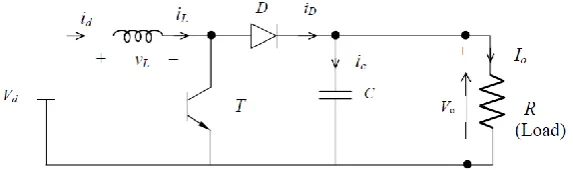
In a boost regulator the output voltage is greater than the input voltage- the name “boost”. A boost regulator using apower MOSFET, the circuit operation can be divided into two modes. Mode 1 beings when transistor M1 switched on at t=0. The input current, which rises, flow through inductor L and transistor Q1.
Figure 2: Mode 1 and Mode 2 operation of boost converter
Mode2 beings when transistor M1 is switched off at t=t1. The current that was flowing through the transistor would now flow through L, C, load, and diode Dm. The inductor current falls until transistor M1 is turned on again in next cycle. The energy stored in inductor L is transferred to the load. The equivalent circuits for the modes of operation are shown in Fig:3 The waveforms for voltage and currents are shown in fig:5 For load current, assuming that the current rises or falls linearly.
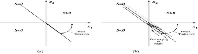
Figure 3: Phase Plot for (a) ideal SM Control (b) actual SM control
The basic idea of SM control is to design first a sliding surface in state space and then the second is to design a control law direct the system state trajectory starting from any arbitrary initial state to reach the sliding surface in finite time, and finally it should come to a point where the system equilibrium state exists that is in the origin point of the phase plane. The existence, stability and hitting condition are the three factors for the stability of sliding mode control. SM control principle is graphically represented in Figure 4, where, represent the sliding surface and x1 and x2 are the voltage error variable and voltage error dynamics respectively. The sliding line (when it is a two variable SM control system in two-dimensional plane) divides the phase plane into two regions. Each region is specified with a switching state and when the trajectory arrives at the system equilibrium point, the system is considered as stable.
III. CONTROL TECHNIQUES FOR BOOST CONVERTER
3.0
Photovoltaic cell:
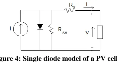
A photovoltaic cell or photoelectric cell is a semiconductor device that converts light to electrical energy by photovoltaic effect. If the energy of photon of light is greater than the band gap then the electron is emitted and the flow of electrons creates current.Figure 4: Single diode model of a PV cell
In this model we consider a current source (I) along with a diode and series resistance (Rs). The shunt resistance (RSH) in parallel is very high, has a negligible effect and can be neglected. The output current from the photovoltaic array is
𝐼 = 𝐼
𝑆𝐶− 𝐼
𝑑𝐼
𝑑= 𝐼
𝑜(𝑒
𝑞𝑉𝐾𝑇𝑑− 1)
where Io is the reverse saturation current of the diode, q is the electron charge, Vd is the voltage across the diode, k is Boltzmann constant (1.38 * 10-19 J/K) and T is the junction temperature in Kelvin (K).
𝐼 = 𝐼
𝑆𝐶− 𝐼
𝑜(𝑒
𝑞𝑉𝐾𝑇𝑑− 1)
Using suitable approximations,
𝐼 = 𝐼
𝑆𝐶− 𝐼
𝑜(𝑒
𝑞 𝑉+𝐼𝑅𝑠𝑛𝐾𝑇− 1)
where, I is the photovoltaic cell current, V is the PV cell voltage, T is the temperature (in Kelvin) and n is the diode ideality factor In order to model the solar panel accurately.
3.1 Maximum Power Point Tracking :
Maximum Power Point Tracking, frequently referred to as MPPT, is an electronic system that operates the Photovoltaic (PV) modules in a manner that allows the modules to produce all the power they are capable of. MPPT is not a mechanical tracking system that “physically moves” the modules to make them point more directly at the sun. MPPT is a fully electronic system that varies the electrical operating point of the modules so that the modules are able to deliver maximum available power.
A typical solar panel converts only 30 to 40 percent of the incident solar irradiation into electrical energy. Maximum power point tracking technique is used to improve the efficiency of the solar panel.
3.2 System Design:
The first step to the design of an SM controller is to develop a state-space description of the converter model in terms of the desired control variables (i.e., voltage and/or current etc,). Our focus in this paper is the application of SM control to converters operating in CCM. The controller under study is a second-order proportional integral derivative (PID) SM voltage controller. Unlike most previously proposed SM voltage controllers, it takes into account an additional voltage error integral term in the control computation to reduce the steady-state dc error of the practical SM controlled system.
A second-order PID type of SM voltage controller is adopted. Fig.5 shows the schematic description of the proposed
SMVC boost converters, where C,L, and
r
L are the capacitance, inductance, and load resistance of the converters, respectively ic ,iL ,and ir are the capacitor, inductor, and load currents, respectively;Vref, Vi, and βνo are the reference,Figure 5: System modelling of sliding mode controller
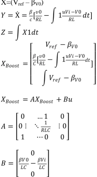
lets consider, voltage error be X, rate of change of voltage error be Y & integral of voltage error be Z. Under continuous conduction mode, derived in can be expressed as,
X=(V
ref– β
V0)
𝑌 = Ẋ =
𝛽𝑐
[
𝜐0𝑅𝐿
− 1
𝑢𝑉𝑖 −𝑉0
𝑅𝐿
𝑑𝑡]
𝑍 = 𝑋1𝑑𝑡
𝑋
𝐵𝑜𝑜𝑠𝑡=
𝑉
𝑟𝑒𝑓− 𝛽
𝑉0𝛽 𝐶
[
𝜐0
𝑅𝐿
− 1
𝑢𝑉𝑖 −𝑉0
𝑅𝐿 𝑑𝑡
𝑉
𝑟𝑒𝑓− 𝛽
𝑉0]
𝑋
𝐵𝑜𝑜𝑠𝑡= 𝐴𝑋
𝐵𝑜𝑜𝑠𝑡+ 𝐵𝑢
𝐴 =
0
… 1
0
0 ⋮ ⋱
𝑅𝐿𝐶1⋮ 0
1
⋯ 0
0
𝐵 =
0
𝛽𝑉 0
𝐿𝐶
−
𝛽𝑉𝑖 𝐿𝐶
0
For this system, it is appropriate to have a general SM control law that adopts a switching function such as, u=1 When S>0,
u=0 When S<0
𝑢 =
1
2(1 + 𝑠𝑖𝑔𝑛 𝑆)
Where S is the instantaneous state variable’s trajectory and is described as,
𝑆 = ⍺
1𝑋
1+ ⍺
2𝑋
2+ ⍺
3𝑋
3= 𝐽
𝑇𝑋
where, ⍺1,⍺2 and ⍺3 are representing control parameter termed as sliding coefficients. A sliding surface can be obtained
by enforcing, S = 0. Finally, the mapping of the equivalent control function onto the duty ratio control d,
where, 0 < 𝑑 = 𝑉𝑐
𝑉𝑟𝑎𝑚𝑝 < 1
gives the following relationship for the control signal Vc and Vramp signal, where
𝑉𝐶 = 𝑈𝑒𝑞𝑢 = −𝛽𝐿
⍺1
⍺2
− 1
𝑅𝐿𝐶 𝑖𝐶+ 𝐿𝐶 ⍺3
⍺2
𝑉𝑟𝑒𝑓 − 𝛽𝑉0 + 𝛽 𝑉0− 𝑉𝑖
𝑉𝐶 = −𝐾𝑝1𝑖𝐶+ 𝐾𝑝2 𝑉𝑟𝑒𝑓 − 𝛽𝑉0 + 𝛽 𝑉0− 𝑉𝑖
𝐾𝑝1= ⍺1
⍺2 −
1
𝑅𝐿𝐶 and 𝐾𝑝2 = 𝐿𝐶 ⍺3
⍺2
𝑉𝑟𝑎𝑚𝑝 = 𝛽 𝑉0− 𝑉𝑖
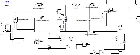
IV. SIMULINK MODEL
Figure 6: Simulated block diagram for boost converter using (a)SM and (b)PID Controller
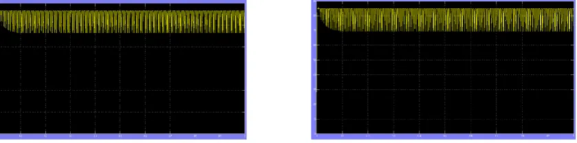
V. RESULT AND DISCUSSION
Figure 8: Simulation result for boost converter using sliding mode controller (a) voltage (b) current.
Figure 9: Simulation result for boost converter using PID controller
Figure 10:simulation result for boost converter using PV cell with MPPT (a) current (b) voltage VI.CONCLUSION
Maximum power point tracking (MPPT) use for maximum possible power from one or more photovoltaic devices. The simulation was first run with the switch on no MPPT mode, bypassing the MPPT algorithm block in the circuit. It was seen that when we do not use an MPPT algorithm, the power obtained at the load side was very low value. Therefore, the conversion efficiency came out to be very low.
REFERENCES
[1]M.H.RASHID,POWER ELECTRONICS:CIRCUITS,DEVICES AND APPLICATIONS (3RD EDITION),PRENTICE HALL,2003.
[2] Utkin V., Guldner J., and Shi J.X., Sliding Mode Control in Electromechanical Systems. London, U.K.: Taylor and Francis, 1999.
[3] Tan S.C., Lai Y.M., Cheung M.K.H. and Tse C.K., \A Fixed-Frequency Pulse-Width-Modulation Based Quasi Sliding Mode Controller for Buck Converters," IEEETransactions on Power Electronics, vol. 20 no. 6, pp. 1379-1392, Nov. 2005.
[4] P. Mattavelli, L. Rossetto, G. Spiazzi, and P. Tenti, “General-purpose sliding-mode controller for dc/dc converter applications,” in Rec. IEEE Electron. Specialists Conf. (PESC’93), Jun. 1993, pp. 609–615.
[5] S. C. Tan, Y. M. Lai, and C. K. Tse, “Adaptive feedforward and feedback control schemes for sliding mode controlled power converters,” IEEE Trans. Power Electron., vol. 21, no. 1, pp. 182–192, Jan. 2006.
[6] H. Sira-Ramirez, “A geometric approach to pulse-width modulated control in nolinear dynamical systems,” IEEE Trans. Automat. Contr., vol.34, no. 3, pp. 184–187, Feb. 1989.
[7] Assad Abu-Jasser, "A Stand-Alone Photovoltaic System, Case Study: A Residence in Gaza", Journal of Applied Sciences in Environmental Sanitation, Vol.5, No.1, pp.81-91, 2010 .
[8] R. Hosseini, N. Hosseini and H. Khorasanizadeh, "An experimental study of combining a photovoltaic system with a heating system", World Renewable Energy Congress, Vol.8, pp.2993-3000, 2011
[9] Mohamed Azab, "A New Maximum Power Point Tracking for Photovoltaic Systems", International Journal of Electrical and Electronics Engineering, Vol.3, No.11, pp.702-705, 2009
[10] M. Gohul, T. Jayachandran, A. Mohamed Syed Ali, T.G. Raju, N. Santhosh Kumar and M.R. Saravanan, "A New Design of Grid Tie Inverter for a Grid Interactive Solar Photovoltaic Power Generation – An Innovative Option for Energy Conservation & Security", International Journal of Electronics & Communication Technology, Vol.2, No.3, pp.161-166, 2011
[11] Klimis Ch. Karasavvas, "Modular simulation of a hybrid power system with diesel, photovoltaic inverter and wind turbine generation", Journal of Engineering Science and Technology Review, Vol.1, pp.38-40, 2008
BIOGRAPHY
Prof.Pradip Kumar Saha, Professor, Jalpaiguri Government Engineering College, Jalpaiguri,WB- 735102. BE (Electrical) from B.E. College, Shibpore. M.Tech((Electrical) Specialization: Machine Drives & Power Electronics from IIT- Kharagpur.PhD from University of North Bengal. FIE, MISTE, Certified Energy Auditor.
Tamal Biswas was born in West Bengal, India on july 19, 1988. He has received his B.Tech degree in Electrical Engineering from Birbhum Institute of Engineering and echnology,Suri, Birbhum, West Bengal in 2012. Currently he is persuing hisM.Tech degree in Power Electronics and Drives from Jalpaiguri Govt. Engineering College, Jalpaiguri, West Bengal.