A track finding algorithm for the inner tracking system of
MPD/NICA
DmitryZinchenko1,2,∗,EduardNikonov3,2, andAlexanderZinchenko1
1LHEP, Joint Institute for Nuclear Research, Dubna, Russia 2Dubna International University, Dubna, Russia
3LIT, Joint Institute for Nuclear Research, Dubna, Russia
Abstract.An inner tracking system (ITS) based on silicon pixel sensors is cur-rently considered as one of the possible MPD upgrade steps. The main purpose of the new detector is to provide a better precision of the primary and secondary vertex reconstruction and improve track reconstruction in MPD in the region close to the interaction point. To study the ITS performance a new track finding algorithm was developed, which better takes into account the new system’s ad-vantages. In this paper the new algorithm is described and first results obtained on simulated data are presented.
1 Introduction
At present, the accelerator complex NICA [1] is being constructed at JINR (Dubna). It is intended for performing experiments to study interactions of relativistic nuclei and polarized particles (protons and deuterons). One of the experimental facilities MPD (MultiPurpose Detector) [2] was designed to investigate nucleus-nucleus, proton-nucleus and proton-proton interactions.
As one of the possible MPD upgrade steps, an Inner Tracking System (ITS) based on the next generation silicon pixel detectors [3] is being considered to be installed between the beam pipe and the Time Projection Chamber (TPC). It is expected that such a detector will increase the research potential of the experiment for both the proton-proton (high luminos-ity) and nucleus-nucleus (high particle multiplicluminos-ity) interactions. According to the proposed design, the MPD ITS will consist of five layers of silicon pixel detectors. The main purpose of the ITS is to provide a better precision of the primary and secondary vertex reconstruction and improve track reconstruction in MPD in the region close to the interaction point.
The existing in MPD track reconstruction method is based on the Kalman filter in the TPC. Its simple extension to the ITS is not adequate to fully exploit the potential of the new detector, therefore such a method can not be considered as a good tool to study ITS perfor-mance. That is why another algorithm, based on the cellular automaton approach [4], was developed. The main idea of the method is to run a combinatorial search of hit pairs belong-ing to the same track usbelong-ing apriori constraints to reduce the combinatorics. Presumably, such a method should produce good results for tracks with relatively small number of hits per track (as is the case for the stand-alone ITS tracking) and can be efficiently implemented in terms of the processing speed.
2 Detector geometry
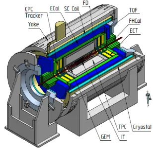
The MPD design is typical for heavy ion collider experiments (Fig. 1). It contains track-ing detectors (time projection chamber TPC and inner tracktrack-ing system IT for the central part, cathode pad chambers CPC and end-cap tracker ECT for the forward region), parti-cle identification systems (time-of-flight system TOF and electromagnetic calorimeter ECal), forward detector FD for triggering purposes and forward hadron calorimeter FHCal for event characterization (centrality measurement). For the present study only the central barrel track-ing detectors TPC and ITS are relevant which are described in some more details below.
Figure 1.MPD detector
The TPC is the main tracking detector of the setup. It is a well-known detec-tor for 3-dimensional tracking and par-ticle identification for high multiplicity events. In the conditions of the maxi-mum charged particle multiplicity∼1000 in central Au+Au collisions and the event rate of about 7 kHz achieved at the NICA design luminosity, the TPC/MPD will provide: efficient tracking up to pseudo-rapidity region|η|=1.2, momentum res-olution for charged particles under 3% in the transverse momentum range 0.1 < pT < 1 GeV/c, two-track resolution of about 1 cm, hadron and lepton identifica-tion bydE/dxmeasurements with a res-olution better than 8%.
The silicon IT is planned to be installed at a later stage. It will be constructed from silicon pixel sensors based on MAPS technology. It will help to solve the following tasks. First, it will enhance track reconstruction for particles registered with all other subsystems. Namely, it will improve the tracking quality for low-pT and/or large-η particles due to its higher η-acceptance and proximity to the beam line (∼3 cm instead of∼40 cm in the TPC). Second, due to its excellent spatial resolution (∼10µm in each direction as compared with∼0.5 mm and
∼1 mm in transverse and longitudinal directions, respectively, for the TPC) it will enhance MPD capabilities for rare probe studies, for example, multistrange hyperons. Moreover, it can bring the open-charm physics sector within reach. In addition, due to its high processing speed it can be used for triggering on rear probes during the high-luminosity running for pp-collisions. For now, 5-layer ITS setup is considered to be used in MPD (Fig.2).
3 Method description
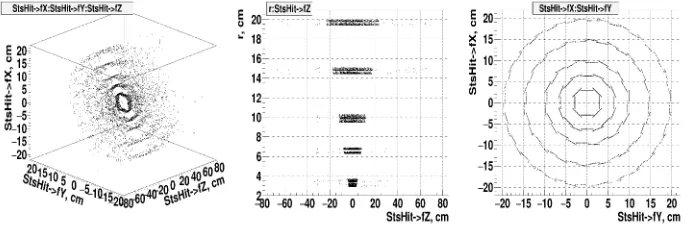
As already mentioned in Sect.1the proposed method is based on the combinatorial search with apriori constraints. The constraints were obtained from the simulation of the ITS detec-tor within the MpdRoot [5] framework. The GEANT3 package was used to transport events with 1000 tracks through the setup and produce ITS hits. The tracks were uniformly dis-tributed inpT from 0.05 to 2 GeV/cand inηfrom -1 to 1. Fig.3shows an example of such an event in several views.
Figure 3.Hits in ITS: left) X vs Y vs Z view; middle) radius in transverse plane vs Z view; right) X vs Y view. Here Z-axis is along the beam direction, X-axis is horizontal and orthogonal to the Z-axis
In order to better understand the method, several definitions should be introduced. At the preprocessing step, every ITS hit is assigned with a correspondingtransverseandlongitudinal angles. The longitudinal angle is an angle between the beam line (Z-axis) and the vector from the interaction point to the hit. The transverse angle is an angle between X-axis and the vector from the interaction point to the hit projection on XY-plane. Hits can be ordered using corresponding angles.
Atrack candidateis a sequence of several hits on different layers of the detector starting from the interaction point, which algorithm considers as belonging to the same track. Trans-verse and longitudinal angles of the track candidate are those of the last hit of the candidate.
The general idea of the proposed algorithm is as follows: assign hits to track candidates using the differences between hit and track candidate transverse and longitudinal angles as matching criteria.
3.1 Longitudinal projection
Figure 4.Left) Track scheme in longitudinal projection; right) longitudinal angle difference as a func-tion ofpT. Broadening of the distribution towards lowpTis caused by the multiple scattering of tracks
in the detector material
3.2 Transverse projection
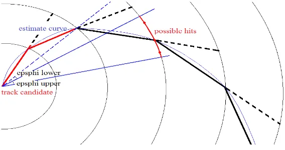
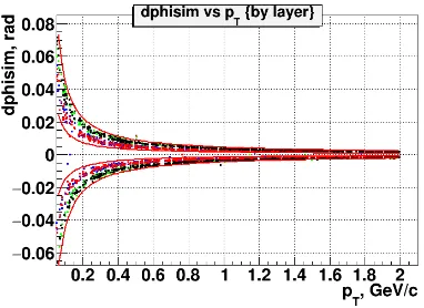
In the transverse projection charged particle trajectories are close to circle arcs because of the magnetic field influence. Therefore, only hits corresponding to the current track candidate curvature (i.e. particle transverse momentum) should be considered as possible track can-didate extensions. Thus, the area of interest can be defined by two anglesepsphiset aside from the track candidate transverse anglephiin the direction defined by the particle charge (see the schematic picture in Fig. 5). The epsphivalues should depend on the estimated transverse momentum pT and can be obtained for MC generated tracks for different layers (Fig.6). One can see that the transverse angle difference for MC tracks slightly depends on the detector layer due to different radial distance between consecutive layers of the ITS (sym-bols with different colors). ThepT-dependence can be approximated by a hyperbola and the acceptance window edges were estimated aseps=±1.5 mrad/pT andeps=±4.5 mrad/pT.
Figure 6. Transverse angle difference for different layers as a function of pT along with the chosen
angular cuts (red lines). Positive and negative values correspond to oppositely charged particles. Blue and red bands correspond to the transverse angle differences for layers 1 and 2, green and black ones to layers 3 and 4
4 Algorithm implementation
The track finding method described above was implemented as follows:
Initialization: Considering that primary tracks start from the interaction point, initial track candidates are built from the first layer hits.
Main algorithm: For each detector layer starting from the second one:
1. Arrange hits by corresponding transverse and longitudinal angles (can be efficiently done using C++multimap container)
2. For each track candidate:
• Estimate transverse particle momentumpTif possible (needs at least 3 hits including interaction point to estimate track curvature)
• Calculate track candidate transverse and longitudinal angles and angular cuts and extract two corresponding hit sets
• Find these two set intersection
• Each hit in the resulting intersection set creates a new track candidate for the next detector layer
The described track finding procedure was implemented within the MpdRoot framework and tested for the Monte Carlo event sample, containing 1000 tracks withpTrange from 0.05 to 2.0 GeV/c. The results showed high efficiency and purity of the method, i.e. only around 2% tracks found contained hits from different MC tracks (false track candidates).
5 Summary and plans
To improve the procedure performance (increase the processing speed) it is foreseen to study the effect of the longitudinal angle cutpT-dependence and transverse angle cut layer-dependence.
Further developments include the method extension for secondary tracks and creation of track fitting and combined ITS-TPC reconstruction procedures. The ultimate goal is to do a comprehensive evaluation of the ITS performance for the open-charm particle selection in pp and gold-gold collisions as was done already (for the pp case) for the TPC-based reconstruc-tion method using Kalman filter track extrapolareconstruc-tion to the ITS (Fig.7).
Figure 7.D-meson selection in pp-collisions at √s=25 GeV: left) reconstructed in ITS decay length of D+(−)-mesons from decays to K−(+)π+(−)π+(−)and background combinations; right) reconstructed invari-ant mass of K−(+)π+(−)π+(−)combinations
References
[1] V. D. Kekelidze et al., Eur. Phys. J. A52, 211 (2016) [2] V. Golovatyuk et al., Eur. Phys. J. A52, 212 (2016)