PROGRAMMABLE LOGIC CONTROLLER BASED VARIABLE SPEED DRIVES FOR EDUCATIONAL TRAINER
CHIN KEN LEONG
A project report submitted in partial fulfillment of the requirement for the award of the
Degree of Master of Electrical Engineering
Faculty of Electrical and Electronic Engineering Universiti Tun Hussein Onn Malaysia
ABSTRACT
ABSTRAK
CONTENTS
TITLE i
DECLARATION ii
DEDICATION iii
ACKNOWLEDGEMENT iv
ABSTRACT v
ABSTRAK vi
CONTENTS vii
LIST OF TABLES xiii
LIST OF FIGURES xiv
LIST OF SYMBOLS AND ABBREVIATIONS xvii
LIST OF APPENDICES xviii
CHAPTER 1 INTRODUCTION 1
1.1 Project Background 1
1.2 Problem Statements 3
1.3 Project Objectives 4
CHAPTER 2 LITERATURE REVIEW 5
2.1 Introduction 5
2.2 Experimental of motor drive in the lab setup 6
2.3 Motor drive 11
2.4 PID Controller 16
2.4.1 Proportional term 17
2.4.2 Integral term 18
2.4.3 Derivative term 18
2.4.4 PID term 19
2.4.5 Tuning the parameters 20
2.4.6 A research on PID controller 21
2.5 PLC Programming based of VSD 23
2.6 Fuzzy Logic 28
2.7 PLC based Fuzzy Logic control system 32
2.8 PLC OMRON CPM2A-40R 34
CHAPTER 3 METHODOLOGY 39
3.1 Project Methodology 39
3.1.1 Phase 1: Literature Review 39
3.1.2 Phase 2: Experimental setup 40
3.1.3 Phase 3: PLC Programming with
basic instruction 40
3.1.4 Phase 4: PLC Programming for Fuzzy Logic 40
3.1.5 Phase 5: Development of Educational Trainer 41
CHAPTER 4 HARDWARE DEVELOPMENT FOR TWO
CONVEYORS PACKAGING SYSTEM 44 41
4.1 The application design for Two
Conveyors Packaging System 44
4.2 Experimental setup of motor drive in the lab
setup 45
4.3 PR10 – Controlling DC brush motor
using MD10C or MD30B 45
4.3.1 PIC microcontroller programming for PR10B 48
4.4 PLC OMRON CPM2A-40R 50
4.5 Installation of application hardware 53
CHAPTER 5 FUZZY LOGIC FOR PLC BASED
APPLICATION PROJECT 55 52
5.1 The Fuzzy Logic Application Design 55
5.2 The Fuzzy Logic Membership 57
CHAPTER 6 PLC PROGRAMMING FOR TWO
CONVEYORS PACKAGING SYSTEM 62
6.1 Sectional Programming of the project 62
6.2 The PLC I/O Assignment 63
6.3 Program to test PLC to signal motor
driver PR10 & MD30B 63
6.4 The Sectional PLC Program for the Project 65
6.6 PLC Program for Input Device
Photoelectric Sensor 71
6.7 PLC Program for Input Device Encoders 75
6.8 The Output Devices PLC Program 78
6.9 PLC Programming Software 81
CHAPTER 7 EDUCATIONAL TRAINER FOR PLC
VSD DC MOTOR 84
7.1 The purpose of the educational trainer 84
7.2 Experiment 1: PLC CPM2A-40R
hardware and addressing 85
7.3 Experiment 2: motor driver hardware
PR10 & MD30B 85
7.4 Experiment 3: PLC program controlled motor driver hardware PR10 & MD30B
and 12V DC motor 86
7.5 Experiment 4: two conveyor packaging
application hardware 88
7.6 Experiment 5: Part sensors PE1 to PE4
PLC programming 90
7.7 Experiment 6:. Encoders (E1 & E2) PLC
programming. 91
7.8 Experiment 7: PLC programmed two
conveyor packaging system 91
7.9 Experiment 8:Fuzzy Logic membership
7.10 Experiment 9: Fuzzy Logic PLC
programmed two conveyor packaging
system 89
7.11 Experiment 10: Comparison of
conventional PLC and Fuzzy Logic PLC
programming 89
CHAPTER 8 CONCLUSION AND FURTHER WORK 93
8.1 Conclusion 93
8.2 Further Work 95
LIST OF TABLES
2.1 Ziegler-Nichols parameter 20
2.2 Ziegler-Nichols tuning rule based on Kcr and Pcr 22
2.3 Tuned PID controller value 23
2.4 CPM2A/CPM2C Function Codes 35
2.5 Alphabetic List by Mnemonic 36
2.6 The input and output specifications for encoder and motor
driver 38
LIST OF FIGURES
2.1 Block diagram of project’s area of concerned 6 2.2 Layout for Module 6-fold IGBT Current Converter 7
2.3 Layout of Servo-brake Control Unit 7
2.4 DC Chopper controller for multi-quadrant operation 8 2.5 Single quadrant operation with a DC shunt wound 9 2.6 Four quadrant operation with a DC shunt wound machine 10 2.7 Three-phase operation with a synchronous machine 10 2.8 Electronic motor with load angle indicator 11
2.9 VSD Schematic diagram 12
2.10 Phase Angle Control of a Universal Motor 13 2.11 PWM Chopper Control of a Universal Motor 13 2.12 The circuit diagram of the unity power factor buck type
PWM rectifier for separately-excited dc motor application 14
2.13 Operation modes of 4-Q field exciter 15
2.14 Current source buck type rectifier 16
2.15 Closed Loop System with PID controller 16
2.16 PID controller schematic 17
2.17 Step response P controller 17
2.18 Step response I and PI controller 18
2.19 Step response D and PD controller 19
2.20 Step response P, PI and PID controller 20 2.21 A block diagram of speed PID controller 21
2.22 Block diagram of BLDCM drive system 23
2.23 Schematic diagram of MOSFET Drive Circuit 25
2.24 Upper Half Driving Signal 25
2.25 Lower Half Driving Signal 26
2.27 Binary logic representation of a discrete temperature value. 28 2.28 (a) Cool air temperature range with (b)dotted lines
showing not cool range. 28
2.29 Fuzzy logic control system. 29
2.30 Input data to a fuzzy logic system represented as counts and
percentages 30
2.31 Output data from a fuzzy logic system represented as
counts and percentages 30
2.32 Fuzzy logic system chart showing both input and output
grades 31 1
2.33 Fuzzy logic controller operation. 32
2.34 The block diagram. 32
2.35 Block diagram of the application 33
2.36 Application layout diagram 33
2.37 Block diagram of operation 34
2.38 CPM2A/CPM2C Pulse Output Functions 37
2.39 PLC to control the motor in closed loop control 38 3.1 Flow chart for the Project implementation 42
4.1 Application Prototype layout diagram 44
4.2 PR10 DC Brush Motor using MD30B 46
4.3 Flow chart for PR10 47
4.4 Schematic diagram for PR10 DC Brush Motor using MD30B 47
4.5 PWM pulse waveform 49
4.6 Timer2 Control Register 49
4.7 PIC 16F876A Program for PR10 and MD30B 50
4.8 Terminal layout diagram for PLC OMRON CPM2A-40R 51 4.9 Wiring connection of PR10+MD30B and PLC Omron
CPM2A-40R 52
4.10 The construction of the project application hardware 53
5.1 Application Prototype layout diagram 55
5.4 Fuzzy system flowchart 58
5.5 Fuzzy input and output membership 60
5.6 Fuzzy Logic Rule Matrix 60
6.1 Sectional PLC programming of the project 62
6.2 I/O connection of PLC 63
6.3 PLC program to test Motor driver PR10 & MD30B (P002) 64 6.4 Main operands and relationship of Sectional programs 65 6.5 Converting fuzzy membership rules to PLC ladder instructions 67 6.6 Fuzzy input membership PLC Program (P004C) 68 6.7 Fuzzy output membership PLC Program (P004D) 69 6.8 I/O Assignment for Fuzzy logic membership PLC Program 70 6.9 Photoelectric sensors to determine the speed of box conveyor 72 6.10 PLC Program for Photoelectric sensors (P004A) 73
6.11 Encoder generates pulses 75
6.12 PLC Program for Encoders (P004B) 76
6.13 Output device program interface with fuzzy output
membership program 78
6.14 Output devices PLC Program (P004E) 79
6.15 Ladder diagram with CX-Programmer 82
6.16 Input/Output Assignment table 82
6.17 Setting the operand address from the I/O assignment table 83 7.1 Terminal layout diagram for PLC OMRON CPM2A-40R 85 7.2 Schematic diagram for PR10 DC Brush Motor using MD30B 86 7.3 Wiring connection of PR10+MD30B and PLC Omron
CPM2A-40R 87
7.4 PLC program to test Motor driver PR10 & MD30B (P002) 88 7.5 The layout diagram of Two Conveyor Packaging System 89 7.6 Main operands and relationship of Sectional programs 89 7.7 Main operands and relationship of sectional programs 90
LIST OF SYMBOLS AND ABBREVIATIONS
VSD - Variable Speed Drive
A – Part Conveyor A (fixed speed)
B – Box Conveyor B (Variable speed)
E1 - Encoder 1 (attached to Conveyor A)
E2 - Encoder 2 (attached to Conveyor B)
PR10 - Cytron Microcontroller board
MD30B - DC brushed Motor Driver
M1 - Motor 1 that drives Conveyor A
M2 - Motor 2 that drives Conveyor B.
X - Value at position that provides the part/box offset data ∆X - the rate of change of the offset
LIST OF APPENDICES
APPENDIX TITLE PAGE
A1 PLC Instruction PID CONTROL 99
A2 Alphabetic List by Mnemonic 102
A3 High-speed Counters 105
B Gantt Chart for project implementation 108
C Cytron PR10B_MD30B 111
D1 The PLC Program of the whole project 123
D2 The I/O and Operands Assignment list 133
E1 Lab sheet for Introduction to CPM2A-40 136
CHAPTER 1
INTRODUCTION
1.1 Project Background
Most of the applications involving rotating machinery require a speed controller to govern the speed of the machine. Currently, most speed control problems, either rotational or linear, use a dedicated digital or microprocessor based controller implementing some combination of PID control scheme. PID based controllers are typically very reliable, however, they often have several limitations that can drastically reduce their performance. Most often the PID speed controllers are implemented using a dedicated controller, which can increase the cost of the overall control system.
Proportional-Integral-Derivative (PID) controllers are still widely used in industrial systems, despite the significant developments of recent years in control theory and technology. This is because they perform effectively for a wide class of processes and operating conditions besides provide robust performance. Furthermore, they are easy and remarkable effectiveness and simplicity to implement using analogue or digital hardware and familiar to engineers.
The need for a stand-alone device, one of the main downfalls of PID controllers, can easily be eliminated by implementing the control scheme from within a general purpose programmable logic controller (PLC). Utilizing a PLC as the primary cerebrum is a common practice in industrial plants. However, in order to accomplish PID control from within a PLC, one frequently needs a PID coprocessor that can be programmed in a language other than the standard PLC ladder logic. These coprocessors, which are often obtained from a company other than the PLC manufacturer, can add a significant amount to the overall PLC cost and therefore work against the goal of reducing the cost of the control system. In addition, the performance of the controller is still hindered by the limitations of PID control.
1.2 Problem Statements
Programmable Logic Controller (PLC) is a general purpose controller where by the functions of the controller are custom designed by the user via the programming. Thus the complexity of the controller functions is very flexible and very much dependent on the programmer experty. Learning of PLC-programming is more effective via well structured practical lab works. In the Automation & Control Lab (EAK) of Electrical Engineering Department, Politeknik Kota Kinabalu, there are some 15 sets of industrial standard PLC OMRON CPM2A-40R used to perform basic PLC programming with simple wiring of Input and output devices such as push buttons, light bulbs, relays etc. There are only several PLC trainers to demonstrate the basic application of PLC programming such as simulation conveyor system, traffic light prototype.
PLC is one of the most widely used controllers in the industrial. This is mainly due to the very flexible and easy-to-learn programming features. There are many motors used to build an industrial application. Thus PLC based motor control system is the key area of concerned to relate PLC to the real industrial environment. However, there is no PLC based industrial motor control trainer available in the lab for the practical purposes. This has initiated the need to develop a research and product by the name as follows:
PROGRAMMABLE LOGIC CONTROLLER BASED VARIABLE SPEED
1.3 Project Objectives
The objectives of this project are as follows:
(i) To construct the application prototype hardware of variable speed drive (VSD) to control a motor.
(ii) To implement the VSD controller using Programmable Logic Controller (PLC) with the standard instruction.
(iii) To implement the VSD controller with Fuzzy Logic method by PLC programming.
(iv) To develop the educational trainer procedures for motor that to be fed by the PLC based VSD controller.
1.4 Project Scopes
The scopes of the project are as follows:
(i) The prototype consists of two 12V DC motor driven conveyors with four part
sensors and two encoders. The purpose of prototype is to implement variable
speed drive (VSD) on one of the motors that can be implemented with PLC
programming.
(ii) The PLC programming is developed with the software of CX-Programmer for PLC
OMRON CPM2A-40R. The VSD motor is to be controlled with PLC conventional
programming utilizing the I/O devices available in the prototype.
(iii) The PLC programs developed for the I/O devices during conventional
programming will be added to the sub programs developed based on the fuzzy
logic membership as the interface to all the I/O devices of prototype.
(iv) The educational trainer procedures consists of the interface between PLC and the
motor and VSD assembly; lab sheet which includes wiring diagram and practical
CHAPTER 2
LITERATURE REVIEW
2.1Introduction
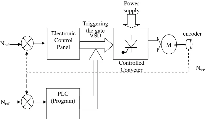
This research, “PROGRAMMABLE LOGIC CONTROLLER BASED VARIABLE SPEED DRIVES FOR EDUCATIONAL TRAINER” consists several important areas of concerned such as PLC, programming, motors, drives, and power electronics. Figure 2.1 shows the block diagram of the area of concerned for this project. The four main objectives to be achieved have outlined the areas of literature review.
(i) To identify the lab equipment to conduct practical works on Variable Speed Drive (VSD) which will includes power electronics and motor. The theory behind this hardware will be obtained from the literature review.
(ii) PLC (OMRON CPM2A-40R) of the Automation and Control Lab will be used in this project. Thus all the instructions and sample programs need to be explored thoroughly so that an effective program can be developed to supply signals to the VSD to control the motor effectively.
(iii) The VSD control will also be implemented via Fuzzy Logic method, thus the theory of fuzzy logic and development of fuzzy relationship algorithm especially on VSD Motor control will be focused and specifically in the area of the PLC approach on fuzzy logic method.
VSD
Figure 2.1: Block diagram of project’s area of concerned
Note: If the control panel and Controlled Converter are unavailable in the lab, the Controlled Converter needs to be fabricated. But the converter will be tested operation by injecting triggering signal to the gate and observing the output waveform at the converter output only.
2.2 Experimental of motor drive in the lab setup
The first objective is to setup the experiment of variable speed drive (VSD) to control a motor. The experimental setup is based on the lab procedures [1] that come with the Universal motor in the Power Electronic and Machine Lab, complete with the Variable
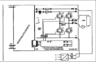
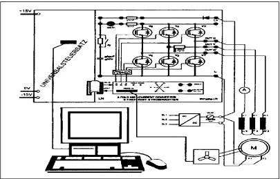
Speed Drive (VSD). Figure 2.2 shows the layout diagram for the test module of the “ 6-fold IGBT Current Converter” which can be connected in various applications for DC and AC motors. Figure 2.3 shows the layout for “Servo-brake Control Unit” used together with the IGBT Current Converter.
Electronic Control
Panel
Nref M
Figure 2.2: Layout for Module 6-fold IGBT Current Converter
The servo-brake is a digital-controlled 4-quadrant precision drive with excellent control characteristics in all modes of operation. It is a robust unit, easy to operate and combines four functions in one unit, there are brake, 4-quadrant drive, load simulation and positioning drive.
The servo-brake is suitable for static and dynamic loading exercises. The complete equipment consists of the control unit and asynchronous machine with resolver. The connection cables are fixed to the control unit and connected to the machine with polarity-reversal protection. Four basic applications (1-4), all different, can be selected at the operating module.
(i) TORQUE CONTROL (loading brake) (ii) SPEED CONTROL (drive)
(iii) INERTIA WHEEL (inertia wheel) (iv) STEP POSITION (position control)
[image:22.595.115.524.472.734.2]The 6-fold IGBT Current Converter Module board can be assembled in several experiments. Figure 2.4 illustrates DC Chopper controller for multi-quadrant operation, where four IGBT are connected to supply a load. The four gate signals are supplied by the controller module.
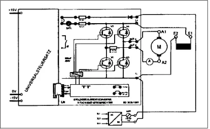
Figure 2.5 illustrates the connection for Single quadrant operation with a DC shunt wound. Only one IGBT is connected to supply a motor and gate signal is supplied by the controller module.
Figure 2.5: Single quadrant operation with a DC shunt wound
Figure 2.6: Four quadrant operation with a DC shunt wound machine
[image:24.595.123.521.399.700.2]Figure 2.8: Electronic motor with load angle indicator
Figure 2.4 to Figure 2.8 show several experiments setup to be connected on the same “6-fold IGBT Current Converter Module board”, with selected components. The signals to the gate of the IGBT are supplied from the Servo Brake Control Unit as shown in Figure 2.3.
2.3 Motor drive
Most of the applications involving rotating machinery require a speed controller to govern the speed of the machine. This device is called Variable Speed Drive (VSD). A typical electric VSD system consists of three basic components, i.e. the electric motor, the power converter, and the control system as illustrated in Figure 2.9. The electric motor is connected directly or indirectly (through gears) to the load. The power converters are usually constructed by power semiconductor switches, basically categorized into two main groups uncontrolled and controlled. The
uncontrolled group usually two terminals such as diode which has no triggering terminal.
Figure 2.9: VSD Schematic diagram
Speed control of universal motors typically employs two scheme, i.e. Phase Angle Control and PWM Chopper Control [2]. Phase Angle Control is the simplest method to control the speed of a universal motor. Figure 2.10 illustrates schematic diagram of Phase Angle Control of a Universal Motor [2]. Speed control is achieved by the varying the firing angle for the TRIAC. Phase angle control is very cost
effective solution but not very efficient and prone to EMI. The Phase Angle Control
mechanism typically employed for speed control of the TRIAC. A phase shift of the
TRIAC gate's pulses allows the effective voltage, seen by the motor to be varied and
hence the speed of the motor. A Zero Crossing Detection circuit is used to establish a
[image:26.595.112.500.127.243.2]timing reference for delaying the firing of the gate pulses.
Figure 2.11 illustrates the schematic diagram of PWM Chopper Control of
a Universal Motor. It is a more advanced solution for controlling the speed of a
universal motor. In this method rectified AC line voltage is switched at a high
frequency by a Power MOFSET or IGBT device to generate time varying voltage for
the motor. Switching frequency is usually in the range of 10 to 20 KHz so as to
eliminate acoustic noise. This method of universal motor control can achieve better
Figure 2.10: Phase Angle Control of a Universal Motor [2]
Figure 2.11: PWM Chopper Control of a Universal Motor[2]
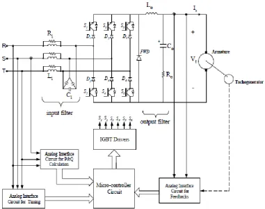
Figure 2.12: The circuit diagram of the unity power factor buck type PWM rectifier for separately-excited dc motor application [3]
The unity pf buck-type PWM rectifier supplies power to the armature circuit of a separately excited dc motor. Each power semiconductor switch consists of an IGBT connected in series with an ultrafast recovery diode, resulting in reverse voltage blocking capability and unidirectional current flow. A low-pass, damped LC filter is connected to the input side of the converter to filter out the switching
frequency harmonic components in the line currents. In order to avoid accelerated ageing in motor insulation due to steep voltage wavefronts, and mechanical failure due to circulating bearing currents, the switching frequency harmonics are filtered out with a damped output filter.
The microcontroller block in Figure 2.12 will generate signals to supply the six gates of IGBT Drivers S1 to S6 to drive the motor. The microcontroller will receive the feedback signal from the motor speed encoder and also the armature current. Beside that the microcontroller inputs also taken from the P&Q and timing of the incoming three phase supply.
four-quadrant (4-Q) dc-dc converter on the field side. The 4-Q dc-dc converter in Fig.2.13 allows both reversing the field current rapidly, and keeping it constant at the preset value against supply voltage fluctuations.
Figure 2.13: Operation modes of 4-Q field exciter [3]
Simplified circuit diagram of a three-phase, current source, buck-type
Figure 2.14: Current source buck type rectifier [3]
2.4 PID Controller
[image:30.595.116.443.583.682.2]The data sheet for AVR221: Discrete PID controller of Atmel (2006) explain the theory of PID controller. This application note describes a simple implementation of a discrete Proportional-Integral-Derivative (PID) controller [4].
Figure 2.15 shows the block diagram of a system with a PID controller. The PID controller compares the measured process value y with a reference setpoint value, y0. The difference or error, e, is then processed to calculate a new process input, u. This input will try to adjust the measured process value back to the desired setpoint. The alternative to a closed loop control scheme such as the PID controller is an open loop controller. Open loop control (no feedback) is in many cases not
satisfactory, and is often impossible due to the system properties. By adding feedback from the system output, performance can be improved.
Figure 2.16 shows the PID controller schematics, where Tp, Ti, and Td denote the time constants of the proportional, integral, and derivative terms respectively.
Figure 2.16: PID controller schematic [4]
2.4.1 Proportional term
[image:31.595.118.409.540.750.2]The proportional term (P) gives a system control input proportional with the error. Using only P control gives a stationary error in all cases except when the system control input is zero and the system process value equals the desired value. In Figure 2.17 the stationary error in the system process value appears after a change in the desired value (ref). Using a too large P term gives an unstable system.
2.4.2 Integral term
The integral term (I) gives an addition from the sum of the previous errors to the system control input. The summing of the error will continue until the system
[image:32.595.119.413.321.557.2]process value equals the desired value, and this result in no stationary error when the reference is stable. The most common use of the I term is normally together with the P term, called a PI controller, this will generate a very small overshoot but settled down to steady state level exactly similar to the reference level (shown in green line). Using only the I term gives slow response and often an oscillating system as shown in the blue line. Figure 2.18 shows the step responses to a I and PI controller. As seen the PI controller response have no stationary error and the I controller response is very slow.
Figure 2.18: Step response I and PI controller
2.4.3 Derivative term
controller. A too large D term usually gives an unstable system. Figure 2.19 shows D and PD controller responses. The response of the PD controller gives a faster rising system process value than the P controller. Note that the D term essentially behaves as a highpass filter on the error signal and thus easily introduces instability in a system and make it more sensitive to noise.
Figure 2.19: Step response D and PD controller
2.4.4 PID term
Using all the terms together, as a PID controller usually gives the best performance. Figure 2.20 compares the P, PI, and PID controllers. PI improves the P by removing the stationary error, and the PID improves the PI by faster response and no
Figure 2.20: Step response P, PI and PID controller [4]
2.4.5 Tuning the parameters
[image:34.595.111.520.644.730.2]The best way to find the needed PID parameters is from a mathematical model of the system, parameters can then be calculated to get the desired response [4]. Often a detailed mathematical description of the system is unavailable, experimental tuning of the PID parameters has to be performed. Ziegler-Nichols method is a well-known online tuning strategy. The first step in this method is setting the I and D gains to zero, increasing the P gain until a sustained and stable oscillation (as close as possible) is obtained on the output. Then the critical gain Kc and the oscillation period Pc is recorded and the P, I and D values adjusted accordingly using Table 2.1.
2.4.6 A research on PID controller
[image:35.595.116.471.389.557.2]Ezwan, M. E. (2008) conducted a research on PID controller as shown in the Figure 2.21. This research involved developing the well-known Ziegler-Nichols tuning algorithms. The error signal, e represents the difference between the speed command and the speed feedback. The proportional control multiplies the speed error e by a constant Kp, the integral control multiplies the e by a constant Ki, to correct steady state error; the derivative control reduces the overshoot and the rise time
U(t) = Kp e(t)+ KpKi ∫o e(t)dt + KpKd de(t)/dt (2.1) where, U(t) is a control signal, Kp is a proportional gain, Ki is a an integral gain, Kd is a derivative gain, e(t) is an error, the term ∫o e(t)dt is a summation of all past error over time and de(t)/dt is rate of change of error term.
Figure 2.21: A block diagram of speed PID controller
For the basic control system, the controller compares the measured value to a set point or reference voltage to get the error value as expressed in equation above and then the error signal will take the appropriate corrective action. The parameter of PID controller, Kp, Ki, and Kd can be manipulated to produce various response curves from a motor controller. For this project, we change voltage to speed. It is because we need to know an error of speed.
where, r(t) is a set point (SP) or reference voltage and y(t) is a measured value (Process Variable)
Ziegler and Nichols proposed rules for determining values of the proportional
gain Kp, integral time Ti, and the derivative time Td based on transient response
characteristics of a given plant. For the Ziegler-Nichols Frequency Response Method,
the critical gain, Kcr and the critical period, Pcr have to be determined first by setting the
Ti = and Td = 0. Increase the value of Kp from 0 to a critical value, Kcr at which the output
first exhibits sustained oscillation. Table 2.2 displayed the Ziegler-Nichols tuning rule.
The step-by-step calculations based on the algorithm given in equation 2.1 & 2.2 are
[image:36.595.108.521.387.705.2]shown below. Table 2.3 shows the tuned PID controller values.
Table 2.2: Ziegler-Nichols tuning rule based on Kcr and Pcr [5]
Type of Controller Kp Ti Td
P 0.5 Kcr ∞ 0
PI 0.45 Kcr Pcr 0
PID 0.6 Kcr 0.5Pcr 0.125Pcr
Kcr = 16
Pcr = 8.324 – 8.321
= 0.003
Tuning the PID controller:
G(s) = Kp (1 + 1/Tis + Tds)
iii. P Mode
Kp = 0.5 Kcr
= 0.5 (16)
= 8
ii. PI Mode
Kp = 0.45 Kcr
= 0.45 (16)
= 7.2
Ki = 1 / Ti
= 1 / (Pcr/1.2)
= 1 / (0.003/1.2)
= 400
i. PID Mode
Kp = 0.6 Kcr
= 0.6 (16)
= 9.6
Ki = 1 / Ti
= 1 / (0.5 Pcr)
= 1 / [0.5(0.003)]
= 666.67
Kd = 0.125 Pcr
= 0.125 (0.003)
Table 2.3: Tuned PID controller value
Type of Controller Kp Ki Kd
P 8 0 0
PI 7.2 400 0
PID 9.6 666.67 0.000375
The PID can be implemented by PLC program instruction. PLC OMRON CPM2A-40R implements PID function with the instruction PID(--). The operands of the instruction and the set values are discussed in detail in Appendix A1.
2.5 PLC Programming based of VSD
Brushed DC motors (BLDCM) have been used in industry due to their linear characteristics and the ease of adjusting their speed through a simple power electronic circuit. Tawadros et al. investigated the possibility of using a PLC (Programmable Logic Controllers) to control such motors rather than
microcontrollers [6]. Maria G. I. (2004) [11] conducted a research of the induction motor system driven by inverter and controlled by PLC prove a higher accuracy in speed regulation as compared to a conventional V f control system. The efficiency of PLC control is increased at high speeds up to 95% of the synchronous speed. Thus, PLC proves themselves as a very versatile and effective tool in industrial control of electric drives..
The PLC takes an action to switch only two NAND gates at any moment driving the output transistors to be switched off which makes the signal to the NAND gate to be high (15V). The effect on the upper half is that the PWM signal will
[image:38.595.114.503.320.493.2]appear on the output on the NAND gate which is applied to the optocoupler. When the optocoupler is on the MOSFET is driven to the off state and vice versa. In the lower half, the MOSFET will be on at all times (no PWM) during the off period of the PLC transistor output. Once the rotor moves and the PLC receives the new position from the feed back sensors, the current off transistor output is activated (switched on) and new one is switched off to drive a different MOSFET (from the upper or lower half based on the BLDCM sequence of operation). All resistors are selected based on the maximum current consumption of each component.
REFERENCES
[1] Lucas Nulle (1998). SO3636-1R, 6-fold IGBT Current Converter, SE2663-6A, Servo-brake Control Unit. Germany: LUCAS-NULLE GmbH Company. [2] Renesas Electronics Corporation (2012). Universal DC Motor Control
Algorithms. Retrieved from http://www.renesas.com/media/applications/
key_technology/motor_control/motor_algorithms/child_folder/UniversalMot orContorl-
[3] Bilgin, H. F., Nadir, K. N. et.el., (2002) “A Unity-Power-Factor Buck-Type PWM Rectifier for Medium/High-Power DC Motor Drive Applications”,
IEEE TRANSACTIONS ON INDUSTRY APPLICATIONS, VOL. 38, NO. 5,
SEPTEMBER/OCTOBER 2002, pp 1412 – 1425.
[4] Atmel Corporation (2006). AVR221: Discrete PID controller. 2558A-AVR-05/06
[5] EZWAN, M. E. (2008) “Speed control of dc motor using PID controller implementation with PLC” . Universiti Malaysia Pahang.
[6] Tawadros, M., Rizk, J. & Nagrial, M. Brushless DC motor control using PLC. School of Engineering, University of Western Sydney (Australia)
[7] Industrial Text & Video Company. Section 5 Advanded PLC Topics and
Networks. Chapter 17 Fuzzy Logic, pg 797 to 844” . Industrial Text & Video Company. Retrived from www.industrialtext.com
[8] Arrofiq, M. & Saad, N.(2007) “PLC-based Fuzzy Logic Controller for
Induction-motor Drive with Constant V/Hz Ratio” International Conference on Intelligent and Advanced Syetems 2007. pp 93 - 98
[10] OMRON (2008). CPM1/CPM1A/CPM2A/ CPM2C/SRM1(-V2)
Programmable Controllers. Programming Manual: Cat. No. W353-E1-06 [11] Maria G. I. (2004). “Design and Implementation of PLC-Based Monitoring
Control System for Induction Motor”. IEEE TRANSACTIONS ON ENERGY CONVERSION, VOL. 19, NO. 3, SEPTEMBER 2004. pp 469 - 476
[12] Serhat, Y., Bekir, C. et. al. (1999). “


![Figure 2.11: PWM Chopper Control of a Universal Motor [2]](https://thumb-us.123doks.com/thumbv2/123dok_us/8772449.899615/27.595.114.477.393.608/figure-pwm-chopper-control-universal-motor.webp)
![Figure 2.13: Operation modes of 4-Q field exciter [3]](https://thumb-us.123doks.com/thumbv2/123dok_us/8772449.899615/29.595.119.505.156.470/figure-operation-modes-q-field-exciter.webp)
