Research Article
August
2017
Computer Science and Software Engineering
ISSN: 2277-128X (Volume-7, Issue-8)
A Study of Smart Antenna for Wireless Application
Monika Sharma*, Anita ChopraDepartment of ECE, Gyanvihar University,Jaipur,
Rajasthan, India
DOI: 10.23956/ijarcsse/V7I8/0130
Abstract— Smart antenna is a next generation antenna which can increase capacity in a cellular communication system, can reduce the effect of the multipath fading, increase the diversity gain, and suppress the co-channel interference between different devices. The antenna operates in conjunction with mobile subscriber unit and provides a plurality of antenna elements. The antenna array creates a beamformer for signals to be transmitted from the mobile subscriber unit, and a directional receiving array to more optimally detect and receive signals transmitted from the base station. By directionally receiving and transmitting signals, multipath fading is greatly reduced as well as intercell interference. In this antenna system at least one active antenna element is active and essentially centrally located within multiple passive antenna elements. The passive antenna elements are coupled to selectable impedance components. Through proper control of the passive antenna element, the cellular communication system directs an antenna beam pattern towards an antenna tower of a base station to maximize gain, and consequently, single-to-noise ratio thus ,optimum reception is achieved, for example an idle mode which receives a pilot signal.
Keywords— Beamforming, CDMA, fading, mobile communication, Smart antenna.
I. INTRODUCTION
A smart antenna system includes a receiving system, one or more beam analysis modules, a control channel monitoring module, a processing system, and a receiving beam switch is provided. The receiving system is operable to receive a plurality of uplink beams, each including traffic signals transmitted by a mobile station. The beam analysis modules are operable to analyze the uplink beams to determine one or more characteristics of each uplink beam. The control channel monitoring module is operable to monitor control channel signals being communicated from a base station transceiver. The control channel signals include synchronization signals. The processing system is operable to synchronize the smart antenna apparatus with the base station transceiver using the synchronization signals received by the control channel monitoring module. The processing system is further operable to determine a selected beam from the plurality of uplink beams based at least in part on the one or more characteristics determined by the beam analysis modules. The receiving beam switch is operable to switch to the selected beam to allow the selected beam to be communicated to the base station transceiver.
II. OBJECTIVES
This paper relates to cellular communication systems and more particularly to an antenna apparatus for use by mobile subscriber unit to providing beamforming transmission and reception capability. CDMA communication may be used to provide wireless communication between base station and one or more mobile subscriber. The base station includes a antenna apparatus for sending forward link radio frequency signal to mobile subscriber unit. The base unit antenna is also responsible for receive reverse link radio frequency, transmitted by mobile subscriber unit.
The most common type of antenna used to transmit and receive signals at mobile subscriber unit is a mono or omni directional antenna this type of antenna consist a single wire or antenna element that is coupled to a transceiver within the subscriber unit. The signal transmitted from a mono pole antenna is omni directional in nature. The signal is sent in all direction with the same signal strength generally in horizontal plane. A monopole antenna does not differentiate in its ability to detect a signal in one direction versus detection of same or a different signal coming from another direction. Another type of antenna which is used by mobile subscriber unit is directional antenna. The system includes a phase shifter attached to the two elements. The phase shifter may be switched on or off in order to affect the phase of signals transmitted or received during communication. By switching the phase shifter on the antenna transmit pattern may be adapted to a pre determined pattern which provides transmit beam pattern area having a concentrated signal strength or gain. The dual element antenna direct the signal into predetermined quadrant to allow for large changes in orientation relative to the base station.
III. PROBLEM FORMULATION
ISSN(E): 2277-128X, ISSN(P): 2277-6451, DOI: 10.23956/ijarcsse/V7I8/0130, pp. 36-40 Here we are computing the weights and beam formed pattern of the linear smart antenna. Here we also calculate mean square error to check the performance of LINEAR smart ANTENNA. The simulation work is divided into three parts. The performance criteria are mean square error and weight error function. We are considering the three different cases.
In the first case signal beam and interference signal beam comes in the different direction i.e. 45o and 60o
In second case signal beam and interference signal beam comes from the same direction i.e. 60o and 60o
In third case signal beam and interference signal beam comes from the same direction i.e. 60o and 60o but the
channel is noisy.
Simulation work is done on MATLAB software. Here we are assuming that the linear array has m elements placed equidistantly along the x-axis.the rectangular planar array has m x n elements placed equidistantly along the x and y axes.
IV. SIMULATION
Beam forming in a smart antenna array makes use of a number of individual antennas and associated signal processors to create a desired transmission radiation patter. For the simulation of work we chose the smart antenna as linear structures. Software used for simulation is MATLAB. MATLAB is a high-level language and interactive environment that enables us to perform computationally concentrated tasks faster than with traditional programming languages such as C, C++, and FORTRAN.
Here we are calculating the performance of the smart antenna system under various conditions. The performance criteria are mean square error and weight error function. We are considering the three different cases. In the first case signal beam and interference signal beam comes in the different direction i.e. 45o and 60o, In second case signal beam and interference signal beam comes from the same direction i.e. 60o and 60o and In third case signal beam and interference signal beam comes from the same direction i.e. 60o and 60o but the channel is noisy.
Table1. Parameters for Simulation
S.No. Array Structure: Linear Type Case-1 Case-2 Case-3
1 Number of elements in linear
smart antenna 8 8 8
2 Spacing (in lambda) between
adjacent elements 0.5 0.5 0.5
3 Pilot signal (SOI) direction in
degree 45 60 60
4 Number of interfering signals
(SNOI) 1 1 1
5 Direction of No. 1 Interference
signal (degree) 60 60 60
6 Enter the mean of the noise NA NA 0
7 Enter the variance of noise NA NA 1
8 AF threshold (db) -40 -40 -40
9 Number of data samples 500 500 500
10 mu (Step size)of LMS algorithm
(0 < Mu < 1) 0.001 0.001 0.001
V. RESULT CASE-1
ISSN(E): 2277-128X, ISSN(P): 2277-6451, DOI: 10.23956/ijarcsse/V7I8/0130, pp. 36-40
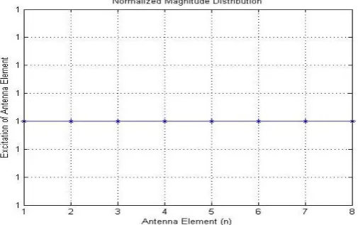
Fig. 3. Diagram showing plot of Normalized magnitude distribution of linear array beamforming (θ=450)
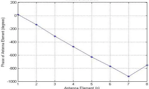
Fig. 4. Diagram showing plot of phase distribution of linear array beamforming (θ=450)
CASE-2
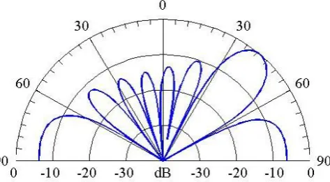
Fig. 7. Diagram showing polar plot of linear array beamforming pattern (θ=600)
ISSN(E): 2277-128X, ISSN(P): 2277-6451, DOI: 10.23956/ijarcsse/V7I8/0130, pp. 36-40
Fig. 10. Diagram showing plot of phase distribution of linear array beamforming (θ=600)
CASE-3
Fig.13. Diagram showing polar plot of linear array beamforming pattern (θ=600, Noisy channel)
Fig.15. Diagram showing plot of Normalized magnitude distribution of linear array beamforming (θ=600, Noisy channel)
ISSN(E): 2277-128X, ISSN(P): 2277-6451, DOI: 10.23956/ijarcsse/V7I8/0130, pp. 36-40
VI. CONCLUSIONS
Here from this paper, we conclude that “Smart Antenna” systems are the antennas with intelligence and the radiation pattern can be varied without being mechanically changed. With appropriate adaptive algorithms the beam forming can be obtained. As the system uses a DSP processor, the signals can be processed digitally and the performance is with a high data rate transmission and good reduction of mutual signal interference.
Here we can understand through simulation that when the signal and interference signal have beams in different directions the maximum mean square error is 1. When signal beam and interference signal beam comes in the same direction the maximum value of mean square error is 1.0046E+00 and when signal beam and interference signal beam comes from the different direction but the channel is noisy the maximum value of mean square error is 1.8189. The corresponding minimum mean square errors are respectively 0, 1.7991E-04 and 1.3377E-04. Weight error function values are also shown in table.
VII. SCOPE OF FUTURE WORK
In this paper, we are computing the weights and beam forming pattern of the linear smart antenna and also calculated the mean square error to check the performance of linear smart antenna. We can do the same experiment with the planner smart antenna and then check the performance of planner smart antenna over linear smart antenna. Here we are using the LMS algorithms but in future Neural Networks or Adaptive Neuro-Fuzzy Inference System (ANFIS) may be considered better robustness to the beamforming algorithms.
REFERENCES
[1] Carl B. Dietrich, Jr., Warren L. Stutzman, Byung-Ki Kim, and Kai Dietze, “Smart Antennas in Wireless
Communications: Base-Station Diversity and Handset Beam forming”, lEEE Antennas and Propagation
Magazine, Vol. 42, No. 5, October 2000.
[2] Michael Chryssomallis, “Smart Antennas”, IEEE Antennas and Propagation Magazine, Vol. 42, No. 3, June 2000.
[3] Brennan L. E., Mallet J. D. and Reed I. S. ―Adaptive Arrays in Airborne MTI Radar, IEEE Trans. Antennas Propagation, 24, pp. 607-615, 1976.
[4] Syed Shah Irfan Hussain,Syed Amjad Hussain Shah and Mohammad Imran Sheikh ―A Mobile Tracking
Algorithm for Adaptive Array Smart Antennas by Adapting the Weights of Transmit Antenna, IEEE transaction
on Smart Antenna pp. 58-63 , jul 2004
[5] Mohammad Tariqul Islam,Zainol Abidin Abdul Rashid ―MI-NLMS adaptive beamformingalgorithm for smart
antenna system applications‖, Journal of Zhejiang University SCIENCE A ,vol 10, pp. 1709-1716 , Jul 2006.
[6] A. H. El Zooghby, C. G. Christodoulou, and M. Georgiopoulos, ―Performance of radia basis function networks for direction of arrival estimation with antenna arrays, IEEE Trans. Antennas Propagat., vol.45, pp. 1611-1617, Nov. 1997
[7] Xin Song, Jinkuan Wang, and Yinghua Han, ―Robust Capon Beamforming in the Presence of Mismatches, Proceedings of ISCIT2005,pp.135-138, July2005.
[8] Nuri Celik, Wayne Kim, Mehmet F. Demirkol, ”Implementation and Experimental verification of Hybrid Smart-Antenna Beamforming Algorithm” IEEE proc. Antenna and wireless propagation letters , vol.5, 2006
[9] R.D.Murch and K. B. Letaief, “Antenna systems for broadband wireless access,” IEEE Commun. Mag., Apr.
2002.