Advances in Radio Science (2004) 2: 135–140
© Copernicus GmbH 2004
Advances in
Radio Science
Over-the-air demonstration of spatial multiplexing at high data
rates using real-time base-band processing
V. Jungnickel, T. Haustein, A. Forck, U. Krueger, V. Pohl, and C. von Helmolt
Fraunhofer Institute for Telecommunications, Heinrich-Hertz Institut, Einsteinufer 37, D-10587 Berlin, Germany
Abstract. Over-the-air transmission experiments with a
real-time MIMO test-bed are reported. We describe in princi-ple a hardware architecture for spatial multiprinci-plexing at high data rates, discuss in detail the implementation on a hybrid FPGA/DSP platform and show measured bit error rates from indoor transmission experiments. Per-antenna rate control and joint transmission are enabled as well using an ideal feed-back link. A functional test of these new techniques is described while detailed transmission experiments are still ongoing.
1 Introduction
Some years ago, basic requirements were outlined for a new air interface which may become effective after the year 2010. A striking challenge is the need to deliver 10 times the data rate at similar costs [1].
There are spectrum, hardware and infrastructure costs in cellular radio systems. It is another issue to reduce the infras-tructure costs, but there may be a trade-off between spectrum and hardware costs using multiple antennas both at the base station and at the mobile terminal forming a multiple-input multiple-output (MIMO) system [2, 3]. Various measure-ments have revealed the potential of MIMO to increase the spectrum efficiency at the same transmitter (Tx) power (see e.g. [4, 5, 6]). To bring these new MIMO techniques into application, the hardware effort must be evaluated, based on implementation trials.
Here we report on a real-time MIMO test-bed where the data rate is limited only by the coherence bandwidth of the indoor propagation channel and not by the digital signal pro-cessing as in an earlier implementation [7]. We report on over-the-air transmission experiments in an indoor environ-ment and show some new features as per-antenna rate control and joint transmission.
The prototype described here has recently been shown at the IEEE Globecom conference in San Francisco in Decem-ber 2003.
Correspondence to: V. Jungnickel ([email protected])
2 The real-time MIMO testbed
The real-time MIMO test-bed was developed in the German HyEff project. The intention is to show the feasibility of MIMO in real-time at first in a single carrier link, based on the well-known flat fading algorithms, and to speed-up the signal processing substantially so that the system becomes limited by the coherence bandwidth of typical indoor chan-nels. Various hardware architectures were evaluated there-fore and a promising approach is implemented and fully op-erational now.
In particular, we use field-programmable gate arrays (FP-GAs) instead of digital signal processors (DSPs) as in [7], for the real-time processing of the base-band signals. The reason therefore is the need to process multiple data streams in a single unit. The limited number of in- and output ports of current DSPs may not allow multiple high data rate streams in parallel. For the most simple MIMO algorithms, as the minimum mean-square error (MMSE) detector, all required components for the real-time processing of the received base-band signals can be integrated on current FPGAs. However, each component must carefully be programmed in VHDL, to allow a proper timing control. [(Calculation of beam steering weights, power allocation and bit loading vector). The typi-cal MIMO algorithms are implemented on a standard DSP.] It is also used to control the system.
The complete system is shown in principle in Fig. 1. It comprises of a transmitter (Tx) unit with 4 antennas and a receiver (Rx) unit with 5 antennas. Digital processing of the discrete-time base-band signals is done using an FPGA both at the Tx and at the Rx, and at the Rx it is complemented by a DSP. The link is currently unidirectional and so a feed-back link from the Rx to the Tx is realized by cable. Since the current implementation focuses on the real-time processing, the frame and symbol synchronization are realized by cables as well.
2.1 Transmitter
Fig. 1. Principle of the real-time MIMO testbed.
Fig. 2. One of the four 5.2 GHz transmitters.
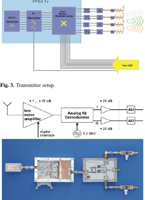
The pilot and data signal generation, the modulation as well as the joint pre-processing using a matrix-vector multi-plication unit are all realized in a XILINX XC2V8000 (see Fig. 3). The 12-bit output signals were DA converted and used to modulate the carrier (see Fig. 3).
Each of the 8 (4 times I and Q each) periodically generated signals consists of a pilot and a data block. A different 127-bit Gold sequence is used as a pilot in each signal to identify at the Rx each I and Q branch from each Tx antenna. Rela-tively long pilots are used to get sufficiently precise channel estimates for the linear joint transmission experiments. The requirements therefore are investigated in [8]. Each pilot is followed by a different pseudo-random data block with 1024 symbols on each stream. The joint symbol clock for all data streams is variable and so the transmission can be adapted to the coherence bandwidth in the channel. The modulation is set independently on each I and Q branch for each antenna with up to 16 PAM levels. The modulation is individually controlled using a binary vector provided externally by the DSP via cable. Note that a branch may be switched off if
Fig. 3. Transmitter setup.
Fig. 4. One of the five 5.2 GHz receivers.
desired. Also the weights for the joint transmission can be controlled by the DSP via the feed-back link.
2.2 Receiver
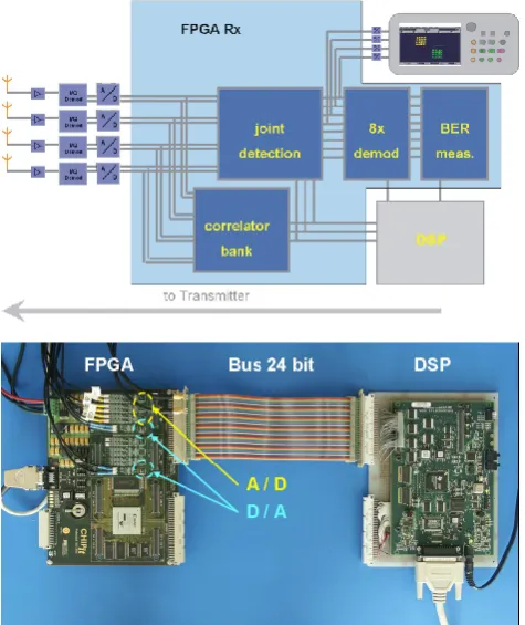
The received signals from 5 antennas are amplified in a digitally controlled low-noise amplifier and directly down-converted in a home-made analogue IQ demodulator (see Fig. 4). The base-band signals are again amplified and digi-tized with 12-bit at a 25 MHz sampling rate.1
An overview of the Rx setup is shown in Fig. 5. It com-prises of the channel estimation circuit, the channel tracking by the DSP, the joint detector, the multiple demodulators and the unit for the bit error rate (BER) measurements.
2.3 Channel estimation
80 correlation circuits (CC) using the known pilot sequences are implemented in the Rx FPGA (XILINX XC2V6000).
1The analogue RF design creates an IQ imbalance comparable
V. Jungnickel et al.: Over-the-air demonstration of spatial multiplexing 137
Fig. 5. Top: Receiver setup. Bottom: A/D converters are on top of
the FPGA (left). A DSP (right) is connected via a parallel bus.
Since binary sequences are used, the CCs need no multiplica-tion. The next bit in the sequence may eventually change the sign of the signal to be accumulated and then the CC switches from addition and subtraction. One such CC requires 23 out of 33.792 slices in the FPGA and so the entire channel esti-mation needs less than 6% of the total resources. The noise variance for the MMSE detector is estimated in an off-line measurement.
The new channel estimates are immediately available after the last bit in the sequence and stored in registers. These reg-isters are read-out by the DSP (Texas Instruments 6713). The read/write operations of the DSP are fully asynchronous to the frame structure, enabled by back-up register pages. For a few ns after a new estimate is finished, the estimation results are transferred to these registers and access from the DSP is not permitted.
2.4 Channel tracking
The DSP is then used to calculate the coefficients of a linear MMSE filter which are then sent back to the weight registers for the joint detection in the FPGA. To achieve a higher mo-bility, it is critical in general to adjust the coefficients in the MMSE detector sufficiently fast. The most time consuming part of the weight calculation is a matrix inversion initially implemented in the DSP using C based on Greville’s method [9]. One such inversion takes some ms depending on the an-tenna configuration. For multy carrier systems, the total time
An overview of the Rx setup is shown in Fig. 5. It
comprises of the channel estimation circuit, the
channel tracking by the DSP, the joint detector, the
multiple demodulators and the unit for the bit error
rate (BER) measurements.
Channel estimation:
80 correlation circuits (CC)
using the known pilot sequences are implemented in
the Rx FPGA (XILINX XC2V6000). Since binary
sequences are used, the CCs need no multiplication.
The next bit in the sequence may eventually change
the sign of the signal to be accumulated and then the
CC switches from addition and subtraction. One such
CC requires 23 out of 33.792 slices in the FPGA and
so the entire channel estimation needs less than 6 % of
the total resources. The noise variance for the MMSE
detector is estimated in an off-line measurement.
The new channel estimates are immediately available
after the last bit in the sequence and stored in registers.
These registers are read-out by the DSP (Texas
Instruments 6713). The read/write operations of the
DSP are fully asynchronous to the frame structure,
enabled by back-up register pages. For a few ns after
a new estimate is finished, access from the DSP to the
registers is not permitted by the FPGA.
Channel tracking:
The DSP is then used to calculate
the coefficients of a linear MMSE filter which are
then sent back to the weight registers in the FPGA. To
achieve a higher mobility, it is critical in general to
adjust the coefficients in the MMSE detector
sufficiently fast. The most time consuming part of the
weight calculation is a matrix inversion initially
implemented in the DSP using plain C based on
Greville’s method [9]. One such inversion takes some
ms depending on the antenna configuration. For the
48 carriers later on used in the 802.11a system, the
total time must be in the order of a ms, however. A
detailed analysis revealed that the same task can in
principle be sped up by a factor of 50 or so by better
using the special matrix-vector skills of the DSP. In
this way, the value for one inversion could reach some
10 µs with the same DSP and so the channel tracking
rate for MIMO in 802.11a with a single DSP would
become sufficiently fast for indoor and pedestrian
applications. Another way might be the interpolation
of the inverse matrices between adjacent carriers. But
our simulations indicate that the numbers of
inversions can noticeably be reduced so only in the
case of rather large coherence bandwidths.
MIMO detection:
As in the Tx, a matrix-vector
multiplication unit is implemented as a MMSE filter
in the Rx FPGA to separate the spatially multiplexed
data streams. The unit consumes 80 out of 144
dedicated multipliers and operates synchronous to the
sampling clock (25 Mio. matrix-vector multiplications
per second).
Demodulation:
The separated streams are individually
demodulated using individual hard decisions in each I
and Q branch according to the modulation format set
by the DSP at the Tx, and the recovered data are
compared inside the FPGA with the transmitted data.
There are counters for the bit-and frame error rate in
each stream also which can be read out by the DSP
and displayed on a screen or stored to the hard disk.
The entire set-up as presented at the Globecom 2003
is shown in Fig. 6.
F
UNCTIONALT
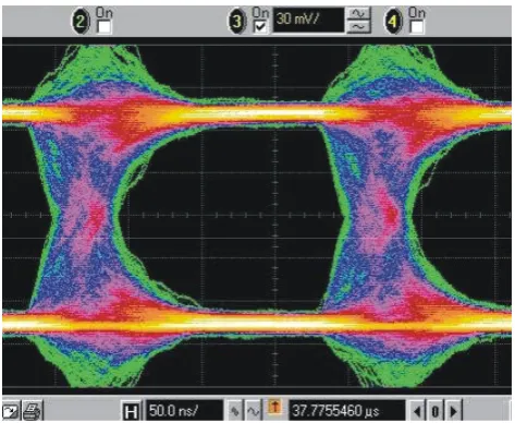
ESTThe eye pattern in a single I branch after both the
transmission with 3 Tx and 4 Rx over a 3 m distance
in an indoor environment and the subsequent MIMO
detection is shown in Fig. 7 at a modulation rate of 5
Mio. symbol vectors per second. The temporal
dispersion in the multi-path indoor channel sets an
upper limit to the maximal clock rate. It leads to the
exponential fall after the start of the bit observed in
Fig. 7. Note that there is additional jitter of about 40
ns which fairly corresponds to the 25 MHz sampling
rate. Now the sampling rate could be increased and
also the processing in the FPGA could be done at
much higher rates.
So our set-up is limited by the coherence bandwidth
of the channel and not by the signal processing. This
is so at least for linear MIMO detection schemes.
Fig. 7: Eye pattern after the separation of streams
in a single I branch with 3 Tx and 4 Rx at
5 million symbol vectors per second (QPSK
modulation on all streams, 30 Mbit/s)
Fig. 6 Over-the-air transmission experiments shown
at the Globecom 2003 conference. The Tx
unit is located in the centre with the antennas
in the top left corner. The receive antennas
are top right and the Rx unit is left from the
scope tower.
Fig. 6. Over-the-air transmission experiments shown at the
Globe-com 2003 conference. The Tx unit is located in the centre with the antennas in the top left corner. The receive antennas are top right and the Rx unit is left from the scope tower.
must be in the order of a ms carrier, as well. A detailed analy-sis revealed that the same task can in principle be sped up by a factor of 50 or so by better using the special matrix-vector skills of the DSP. In this way, the value for one inversion could reach some 10µs with the same DSP and so the chan-nel tracking rate would become sufficiently fast for indoor and pedestrian applications. Another way might be the in-terpolation of the inverse matrices between adjacent carriers. But our simulations indicate that the numbers of inversions can noticeably be reduced so only in the case of rather large coherence bandwidths.
2.5 Joint detection
A matrix-vector multiplication unit is implemented and used as a MMSE filter in the Rx FPGA to separate the spatially multiplexed data streams. The unit consumes 80 out of the 144 dedicated multipliers and operates synchronous to the sampling clock (25 Mio. matrix-vector multiplications per second).
2.6 Demodulation
138 V. Jungnickel et al.: Over-the-air demonstration of spatial multiplexing
comprises of the channel estimation circuit, the
channel tracking by the DSP, the joint detector, the
multiple demodulators and the unit for the bit error
rate (BER) measurements.
Channel estimation:
80 correlation circuits (CC)
using the known pilot sequences are implemented in
the Rx FPGA (XILINX XC2V6000). Since binary
sequences are used, the CCs need no multiplication.
The next bit in the sequence may eventually change
the sign of the signal to be accumulated and then the
CC switches from addition and subtraction. One such
CC requires 23 out of 33.792 slices in the FPGA and
so the entire channel estimation needs less than 6 % of
the total resources. The noise variance for the MMSE
detector is estimated in an off-line measurement.
The new channel estimates are immediately available
after the last bit in the sequence and stored in registers.
These registers are read-out by the DSP (Texas
Instruments 6713). The read/write operations of the
DSP are fully asynchronous to the frame structure,
enabled by back-up register pages. For a few ns after
a new estimate is finished, access from the DSP to the
registers is not permitted by the FPGA.
Channel tracking:
The DSP is then used to calculate
the coefficients of a linear MMSE filter which are
then sent back to the weight registers in the FPGA. To
achieve a higher mobility, it is critical in general to
adjust the coefficients in the MMSE detector
sufficiently fast. The most time consuming part of the
weight calculation is a matrix inversion initially
implemented in the DSP using plain C based on
Greville’s method [9]. One such inversion takes some
ms depending on the antenna configuration. For the
48 carriers later on used in the 802.11a system, the
total time must be in the order of a ms, however. A
detailed analysis revealed that the same task can in
principle be sped up by a factor of 50 or so by better
using the special matrix-vector skills of the DSP. In
this way, the value for one inversion could reach some
10 µs with the same DSP and so the channel tracking
rate for MIMO in 802.11a with a single DSP would
become sufficiently fast for indoor and pedestrian
applications. Another way might be the interpolation
of the inverse matrices between adjacent carriers. But
our simulations indicate that the numbers of
inversions can noticeably be reduced so only in the
case of rather large coherence bandwidths.
MIMO detection:
As in the Tx, a matrix-vector
multiplication unit is implemented as a MMSE filter
in the Rx FPGA to separate the spatially multiplexed
data streams. The unit consumes 80 out of 144
dedicated multipliers and operates synchronous to the
sampling clock (25 Mio. matrix-vector multiplications
per second).
Demodulation:
The separated streams are individually
demodulated using individual hard decisions in each I
and Q branch according to the modulation format set
by the DSP at the Tx, and the recovered data are
compared inside the FPGA with the transmitted data.
There are counters for the bit-and frame error rate in
each stream also which can be read out by the DSP
and displayed on a screen or stored to the hard disk.
The entire set-up as presented at the Globecom 2003
is shown in Fig. 6.
F
UNCTIONAL
T
EST
The eye pattern in a single I branch after both the
transmission with 3 Tx and 4 Rx over a 3 m distance
in an indoor environment and the subsequent MIMO
detection is shown in Fig. 7 at a modulation rate of 5
Mio. symbol vectors per second. The temporal
dispersion in the multi-path indoor channel sets an
upper limit to the maximal clock rate. It leads to the
exponential fall after the start of the bit observed in
Fig. 7. Note that there is additional jitter of about 40
ns which fairly corresponds to the 25 MHz sampling
rate. Now the sampling rate could be increased and
also the processing in the FPGA could be done at
much higher rates.
So our set-up is limited by the coherence bandwidth
of the channel and not by the signal processing. This
is so at least for linear MIMO detection schemes.
Fig. 7: Eye pattern after the separation of streams
in a single I branch with 3 Tx and 4 Rx at
5 million symbol vectors per second (QPSK
modulation on all streams, 30 Mbit/s)
Fig. 6 Over-the-air transmission experiments shown
at the Globecom 2003 conference. The Tx
unit is located in the centre with the antennas
in the top left corner. The receive antennas
are top right and the Rx unit is left from the
scope tower.
Fig. 7. Eye pattern after the separation of streams in a single I
branch with 3 Tx and 4 Rx at 5 million symbol vectors per second (QPSK modulation on all streams, 30 Mbit/s).
3 Functional test
The eye pattern in a single I branch after the transmission with 3 Tx and 4 Rx over a 3 m distance in an indoor en-vironment and the subsequent MIMO detection is shown in Fig. 7 at a modulation rate of 5 Mio. symbol vectors per sec-ond. The temporal dispersion in the multi-path indoor chan-nel sets an upper limit to the maximal clock rate. It leads to the exponential fall after the start of the bit as observed in Fig. 7. Note that there is additional jitter of about 40 ns which corresponds to the 25 MHz sampling rate.
So our set-up is limited by the coherence bandwidth of the channel and not by the signal processing. Further increase of the symbol vector rate is possible in principle by increasing the sampling rate and the clock of the joint dection unit, but it requires the use of multi-carrier techniques as OFDM.
More efficient iterative MIMO detection schemes as V-BLAST were not yet implemented. Unlike in DSPs, a ded-icated processing and memory architecture is required for real-time operation. Even if this might be possible in princi-ple, the effort to implement these algorithms on the register transfer level is not negligible.
4 Transmission experiments
4.1 Fixed rate results
For the transmission experiments, up to 4 Tx and 5 Rx an-tennas were used in an indoor scenario. In order to realize a sufficient channel statistics, the transmitter is placed on a wagon and moved along a 5 m line through the room, which measures about 90 full carrier wavelength at 5.2 GHz. To measure the average bit error rate (BER), the bit errors are accumulated over the whole run. But at low speed it is pos-sible to investigate the instantaneous BER as well. In the
More efficient iterative MIMO detection schemes as
V-BLAST were not yet implemented. Unlike in DSPs,
a dedicated processing and memory architecture is
required for real-time operation. Even if this might be
possible in principle, the effort to implement these
algorithms also on the register transfer level is not
negligible.
T
RANSMISSIONE
XPERIMENTSFixed rate results:
For the transmission experiments,
up to 4 Tx and 5 Rx antennas were used in an indoor
scenario. In order to realize an sufficient channel
statistics, the transmitter is placed on a wagon and
moved along a 5 m line through the room, which
measures about 90 full carrier wavelength at 5.2 GHz.
To measure the average bit error rate (BER), the bit
errors are accumulated over the whole run. But at low
speed it is possible to investigate the instantaneous
BER as well. In the results shown in Fig. 8, the
transmitter power is held fixed in each run, and a
separate run was made for each power value. The Rx
antennas were always more than 2 m away from the
Tx and even though the line-of-sight (LOS) was free
at most locations, the variation of the mean Rx power
is within a few dB, due to the rich multi-path
propagation. It leads to a more or less homogeneous
power distribution in the entire room. So this variation
is left included in the results.
When changing the number of Tx and Rx, the
influence of the diversity is clearly obvious from the
results in Fig. 8. It is obvious that the diversity order
increases as N
Rx-N
Tx+1 as predicted for the MMSE
detector at large SNR. So the transmission becomes
the more reliable the larger the difference between the
number of receivers N
Rxand transmitters N
Txis. The
dashed lines correspond to the theory curves and they
agree fairly well with the measured data.
Note that there is always an error floor at high Tx
powers due to the frequency-selective nature of the
channel (It disappears when the symbol rate is
reduced). The position of these floors agrees very well
with the theoretical analysis in [9]. In particular, the
floor reduces when the diversity order increases.
These floors clearly indicate that now we need
multi-carrier techniques to further increase the system
bandwidth.
Variable rate results:
Per-antenna rate control (PARC,
[8]) is proposed for MIMO links to approach the
channel capacity. With optimal but very complex
schemes, as maximum likelihood detection, the
PARC is just required to achieve this goal. But with
the reduced complexity schemes, the PARC may be
required also to save a reliable transmission over the
MIMO channel. Note that the MIMO channel matrix
may eventually become close to singular. This
situation can be observed even in a rich-scattering
indoor environment. With such reduced complexity
schemes, a sudden increase of the noise after the
MIMO detector can be frequently be observed when a
reduced-complexity detection scheme is used. At first
one might attribute these events to some instability in
the signal processing. But as soon as the PARC is
switched on, this apparent instability is no longer
noticeable, and the system is operational in a much
more stable mode.
The PARC is implemented in a rather unconventional
fashion in our test-bed. As mentioned above, there are
IQ-imbalances due to the RF design and so the noise
in the I and Q branches corresponding to a given Tx
antenna may differently be enhanced after the
separation of the data streams with the real-valued
MMSE detector
3. So it is natural to use the more
simple multi-level modulation in each I and Q branch
and steer the number of bits per branch individually.
This allows a smoother link adaptation in steps of
1 bps/Hz and also the demodulator design is more
simple due to the individual 1-D decisions, compared
3
This is observed also in the estimated real-valued channel
matrices. Without IQ imbalance, two singular values should
be degenerate. Including the imbalance, they are no longer
degenerate.
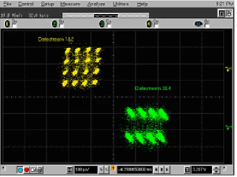
Fig. 9: Variable rate results with 4 Tx and 5 Rx
antennas. A snapshot from the modulation of
the third and fourth antenna signals is shown
after the MMSE filter. While the former uses
the same modulation in the I and Q branches,
the signal on the fourth antenna is more
favourably transmitted when 4 and 2 levels
are used in the I and Q branches, respectively.
Fig. 8: Fixed rate experimental results of the mean
uncoded bit error rates in an indoor scenario.
The increase of the diversity is clearly evident
when more receivers than transmitters are
used.
Fig. 8. Fixed rate experimental results of the mean uncoded bit error
rates in an indoor scenario. The increase of the diversity is clearly evident when more receivers than transmitters are used.
results shown in Fig. 8, the transmitter power is held fixed in each run, and a separate run was made for each power value. The Rx antennas were always more than 2 m away from the Tx and even though the line-of-sight (LOS) was free at most locations, the variation of the mean Rx power is within a few dB, due to the rich multi-path propagation. It leads to a more or less homogeneous power distribution in the entire room [6]. So this variation is left included in the results.
When changing the number of Tx and Rx antennas, the in-fluence of the diversity is clearly obvious from the results in Fig. 8. It is observed that the diversity order increases as NRx
-NTx+1 as predicted for the MMSE detector at large SNR. So
the transmission becomes the more reliable the larger the dif-ference between the numbers of receivers NRxand
transmit-ters NT xis. The dashed lines correspond to the theory curves
and they agree fairly well with the measured data.
Note that there is always an error floor at high Tx powers due to the frequency-selective nature of the channel (It dis-appears when the symbol rate is reduced). The position of these floors agrees very well with the theoretical analysis in [10]. In particular, the floor reduces when the diversity or-der increases. These floors indicate again that now we need multi-carrier techniques to further increase the symbol vector rate.
4.2 Variable rate results
V. Jungnickel et al.: Over-the-air demonstration of spatial multiplexing 139
More efficient iterative MIMO detection schemes as
V-BLAST were not yet implemented. Unlike in DSPs,
a dedicated processing and memory architecture is
required for real-time operation. Even if this might be
possible in principle, the effort to implement these
algorithms also on the register transfer level is not
negligible.
T
RANSMISSIONE
XPERIMENTSFixed rate results: For the transmission experiments,
up to 4 Tx and 5 Rx antennas were used in an indoor
scenario. In order to realize an sufficient channel
statistics, the transmitter is placed on a wagon and
moved along a 5 m line through the room, which
measures about 90 full carrier wavelength at 5.2 GHz.
To measure the average bit error rate (BER), the bit
errors are accumulated over the whole run. But at low
speed it is possible to investigate the instantaneous
BER as well. In the results shown in Fig. 8, the
transmitter power is held fixed in each run, and a
separate run was made for each power value. The Rx
antennas were always more than 2 m away from the
Tx and even though the line-of-sight (LOS) was free
at most locations, the variation of the mean Rx power
is within a few dB, due to the rich multi-path
propagation. It leads to a more or less homogeneous
power distribution in the entire room. So this variation
is left included in the results.
When changing the number of Tx and Rx, the
influence of the diversity is clearly obvious from the
results in Fig. 8. It is obvious that the diversity order
increases as N
Rx-N
Tx+1 as predicted for the MMSE
detector at large SNR. So the transmission becomes
the more reliable the larger the difference between the
number of receivers N
Rxand transmitters N
Txis. The
dashed lines correspond to the theory curves and they
agree fairly well with the measured data.
Note that there is always an error floor at high Tx
powers due to the frequency-selective nature of the
channel (It disappears when the symbol rate is
reduced). The position of these floors agrees very well
with the theoretical analysis in [9]. In particular, the
floor reduces when the diversity order increases.
These floors clearly indicate that now we need
multi-carrier techniques to further increase the system
bandwidth.
Variable rate results: Per-antenna rate control (PARC,
[8]) is proposed for MIMO links to approach the
channel capacity. With optimal but very complex
schemes, as maximum likelihood detection, the
PARC is just required to achieve this goal. But with
the reduced complexity schemes, the PARC may be
required also to save a reliable transmission over the
MIMO channel. Note that the MIMO channel matrix
may eventually become close to singular. This
situation can be observed even in a rich-scattering
indoor environment. With such reduced complexity
schemes, a sudden increase of the noise after the
MIMO detector can be frequently be observed when a
reduced-complexity detection scheme is used. At first
one might attribute these events to some instability in
the signal processing. But as soon as the PARC is
switched on, this apparent instability is no longer
noticeable, and the system is operational in a much
more stable mode.
The PARC is implemented in a rather unconventional
fashion in our test-bed. As mentioned above, there are
IQ-imbalances due to the RF design and so the noise
in the I and Q branches corresponding to a given Tx
antenna may differently be enhanced after the
separation of the data streams with the real-valued
MMSE detector
3. So it is natural to use the more
simple multi-level modulation in each I and Q branch
and steer the number of bits per branch individually.
This allows a smoother link adaptation in steps of
1 bps/Hz and also the demodulator design is more
simple due to the individual 1-D decisions, compared
3
This is observed also in the estimated real-valued channel
matrices. Without IQ imbalance, two singular values should
be degenerate. Including the imbalance, they are no longer
degenerate.
Fig. 9: Variable rate results with 4 Tx and 5 Rx
antennas. A snapshot from the modulation of
the third and fourth antenna signals is shown
after the MMSE filter. While the former uses
the same modulation in the I and Q branches,
the signal on the fourth antenna is more
favourably transmitted when 4 and 2 levels
are used in the I and Q branches, respectively.
Fig. 8: Fixed rate experimental results of the mean
uncoded bit error rates in an indoor scenario.
The increase of the diversity is clearly evident
when more receivers than transmitters are
used.
Fig. 9. Variable rate results with 4 Tx and 5 Rx antennas. A
snap-shot from the modulation of the third and fourth antenna signals is shown after the MMSE filter. While the former uses the same mod-ulation in the I and Q branches, the signal on the fourth antenna is more favourably transmitted when 4 and 2 levels are used in the I and Q branches, respectively.
might attribute these events to some instability in the signal processing. But as soon as the PARC is switched on, this ap-parent instability is no longer noticeable, and the system is operational in a more stable mode.
The PARC is implemented as follows in our test-bed. As mentioned above, there are IQ-imbalances due to the RF de-sign and so the noise in the I and Q branches corresponding to a given Tx antenna may be different after the separation of the data streams with the real-valued MMSE detector2. So it is natural to use multi-level modulation in each I and Q branch and steer the number of bits per branch individually. This allows a smooth link adaptation in steps of 1 bps/Hz. The demodulator design is more simple due to the individ-ual 1-D decisions, compared to the 2-D decisions normally required, at least for 8-PSK, 32- and 128-QAM.
The PARC implementation is based on the signal to noise and interference ration (SINR) in each branch after the joint MMSE filter. The SINR is a side result from calculating the filter coefficients in the DSP. In order to guarantee a certain quality of service in each branch, i.e. a certain BER, the effective SNR is compared to a list of pdefined values re-quired for that BER and then the modulation is set so that the currently available SNR satisfies the requirement. If data streams are not used, the weights are again obtained using the reduced channel matrix.
A typical IQ diagram of two separated antenna signals af-ter the MMSE filaf-ter is shown in Fig. 9. The mixed-mode modulation formats observed in the oscilloscope screen-shot are used by the scheduling algorithm on occasion. Note that
2This is observed also in the estimated real-valued channel
ma-trices. Without IQ imbalance, there are always pais of singular val-ues which are degenerate. Including the imbalance, they are no longer degenerate.
to the 2-D decisions normally required for 8-PSK, 32-
and 128-QAM detection.
The PARC implementation is based on the noise
enhancement in each branch which is a side result
obtained from calculating the filter coefficients in the
DSP. In order to guarantee a certain quality of service
in each branch, i.e. a certain BER, the effective SNR
is compared to a list of pre-defined values required for
that BER and then the modulation is set so that the
currently available SNR is just above the requirement.
A typical IQ diagram of two separated antenna signals
after the MMSE filter is shown in Fig. 9. The
mixed-mode modulation formats seen in the oscilloscope
screen-shot are indeed used by the scheduling
algorithm on occasion. Note that the noise is
especially anisotropic just in the IQ diagram of the
particular antenna, where the scheduling algorithm
has decided to use a mixed modulation. Such
anisotropic noise enhancement is typical for MIMO
detection with the MMSE algorithm.
In the indoor set-up with 4 Tx and 5 Rx antennas and
at high SNR, the scheduling algorithm occasionally
decides in favour of 256-QAM constellation in
favourable channels. But the BER in these streams is
too large due to the non-linearity of the IQ mixers at
the Tx. After a careful adjustment of the local
oscillator power and the modulation amplitudes,
error-free detection of 64-QAM becomes possible. So
with 4 Tx antennas the maximal spectral efficiency is
24 bps/Hz. Depending on both the channel condition
and the SNR, typical values range between 10 and 20
bps/Hz corresponding to data rates between 50 and
100 Mbit/s at 5 Mio. symbol vectors per second.
Note that the adaptation tends to switch off one or
more antenna signals at low SNR, while the
remaining streams are transmitted at higher-level
modulation formats.
Altogether we have observed that the PARC makes
the MIMO with simple detection schemes much more
reliable and it should definitely be used when the
channel changes slowly enough to provide feed-back,
as in indoor or pedestrian applications. From the
signal processing point of view, we feel that
introducing the individual rate control for the parallel
streams may be more efficient than using a more
complex detection scheme at the receiver. Such
pre-adaptation methods at the transmitter may become a
distinct feature in future wireless systems since they
reduce the signal processing effort significantly while
maintaining a high quality of service.
Joint transmission using adaptive channel inversion:
In the down-link of mobile communication systems, it
may be desirable to jointly pre-process the data for
multiple users and transmit them at the same time at
the same frequency using multiple transmit antennas
at the base station. Of course, such joint transmission
(JT) methods need channel side information at the
transmitter, which can be realized via a feed-back link
or by exploiting the channel reciprocity available in
TDD systems up to moderate mobility. The most
simple way to realize JT is to multiply the transmitted
data streams with the pseudo-inverse of the channel
matrix and so the striking new feature of JT can best
be explained.
In particular, the JT separates the data streams in
advance so that each user receives only the desired
signal, while the signals of all other users are forced
to zero. But this forcing of zeros is costly in terms of
the Tx power. When the channel matrices become
close to singular on occasion, the Tx power tends to
infinity. These outage events become less likely when
more base station antennas than users are in the
system. But a scheduling approach to achieve this at
least temporarily may be quite useful as well. If the
channel becomes singular, there are rather frequently
just one or two users for which the zero-forcing
substantially increases the transmitter power. By
interrupting the link to those users and transmitting
with the whole power to the other users for a while,
on average a higher throughput can be achieved for all
users. This is called adaptive channel inversion (ACI)
and it is investigated in great detail [12, 13]. In
particular it was found that the channel capacity can
so be achieved, at least for small SNR, while for high
SNR there is a minor penalty.
Using the perfect feed-back link in our test-bed, we
have realized the JT based on ACI. A screenshot
shows the base-band signals from two antennas
immediately after the AD conversion. Obviously there
is no more cross-talk among the user’s signals
noticeable, as desired. At least when the users move
slowly, the 64-QAM signals can be detected without
joint signal processing at two separate receivers and,
consequently, the two streams can be assigned to two
distinct users.
C
ONCLUSIONSIn conclusion, we have described a
software-reconfigurable real-time test-bed for MIMO
transmission experiments at high data rates in which
the speed of the signal processing is limited only by
the coherence bandwidth in the channel. Using the
well-known flat-fading linear MMSE algorithm with
4 transmitters and 5 receivers, over-the-air data
Fig. 10: Two user’s signals after jointly pre-processing
them based on adaptive channel inversion and
transmitting the resulting signals with 4
antennas at the base station. These signals
shown were immediately tapped after the AD
conversion at the receivers indicating no
noticeable cross-talk.
Fig. 10. Two user’s signals after jointly pre-processing them based
on adaptive channel inversion and transmitting the resulting signals with 4 antennas at the base station. These signals shown were im-mediately tapped after the AD conversion at the receivers indicating no noticeable cross-talk.
the noise is anisotropic in the IQ diagram of the particular antenna, where the scheduling algorithm has decided to use a mixed modulation.
In the indoor set-up with 4 Tx and 5 Rx antennas and at high SNR, the scheduling algorithm occasionally decides in favour of 256-QAM constellation in favourable channels. But the BER in these streams is too large due to the non-linearity of the IQ mixers at the Tx. After a careful adjust-ment of the local oscillator power and the modulation ampli-tudes, error-free detection of 64-QAM module signals is pos-sible. So with 4 Tx antennas the maximal spectral efficiency is 24 bps/Hz. Depending on both the channel condition and the SNR, typical values range between 10 and 20 bps/Hz cor-responding to data rates between 50 and 100 Mbit/s at 5 Mio. symbol vectors per second.
Note that the adaptation tends to switch off one or more an-tenna signals at low SNR, while the remaining streams may be transmitted at higher-level modulation formats.
Altogether we have observed that the PARC makes the MIMO communication with simple detection schemes more reliable and it should be used when the channel changes slowly enough to provide feed-back, as in indoor or pedes-trian applications. With respect to the signal processing ef-fort we feel that introducing the individual rate control for the parallel streams at the transmitter may be more efficient than using a more complex detection scheme at the receiver. Such pre-adaptation at the transmitter may be a distinct feature in future wireless systems since it reduces the signal process-ing effort significantly while it maintains a high quality of service.
multiple antennas at the base station. Of course, such a joint transmission (JT) needs channel side information at the trans-mitter, which can be realized via a feed-back link or by ex-ploiting the channel reciprocity available in TDD systems up to moderate mobility. The most simple way to realize JT is to multiply the transmitted data streams with the pseudo-inverse of the channel matrix and in this way the striking new feature of JT can best be explained.
In particular, the JT separates the data streams in advance so that each user receives only the desired signal, while the signals of all other users are forced to zero. But this forc-ing of zeros is costly in terms of the Tx power. When the channel matrices become close to singular on occasion, the Tx power tends to infinity. These outage events are less likely when more base station antennas than users are in the system. But a scheduling approach to achieve this at least temporar-ily may be useful as well. If the channel becomes singular, there are rather frequently just one or two users for which the zero-forcing criterion substantially increases the transmitter power. By interrupting the link to those users and transmit-ting with the whole power to the other users for a while, on average a higher throughput can be achieved for all users. This is called adaptive channel inversion (ACI) and investi-gated [12, 13]. In particular it was found that the channel capacity can so be achieved, at least for small SNR, while for high SNR there is some penalty.
Using the perfect feed-back link in our test-bed, we have realized the JT based on ACI. A screenshot in Fig. 10 shows the base-band signals from two Rx antennas immediately af-ter the AD conversion. Obviously there is no more cross-talk among the user’s signals noticeable, as desired. At least when the users move slowly, the 64-QAM signals can be de-tected without joint signal processing at the two receivers. Consequently, the two streams can be assigned to two sepa-rate users.
5 Conclusions
In conclusion, we have described a software-reconfigurable real-time test-bed for MIMO transmission at high data rates in which the speed of the signal processing is limited only by the coherence bandwidth in the channel. Using the well-known flat-fading linear MMSE algorithm with 4 trans-mitters and 5 receivers, over-the-air data transmission was demonstrated in the up-link. We have shown that per-antenna rate control may significantly improve the stability of the MIMO radio link. It avoids already in advance the frequent outage events occurring after reduced-complexity MIMO de-tection schemes. For the down-link, joint transmission exper-iments using adaptive channel inversion have been described as well, still based on a perfect feed-back link. Future work is directed to the demonstration of JT in time-division duplex mode based on the channel reciprocity and to the implemen-tation of MIMO-OFDM to further increase the symbol vector rate.
Acknowledgements. This work was supported by the German Min-istry of Research and Education (BMBF) in the project HyEff.
References
[1] available: www.wireless-world-research.org/general info/ Bookofvisions/Bov.html.
[2] Foschini, G. J. and Gans, M. J.: On Limits of Wireless Commu-nications in a Fading Environment When Using Multiple Anten-nas, Wireless Personal Communications, 6, 3, 311, 1998. [3] Golden, G. D., Foschini, G. J., Valenzuela, R. A., and
Wolnian-sky, P. W.: Detection Algorithm and Initial Laboratory Results using the V-BLAST Space-Time Communication Architecture, Electronics Letters, 35, 1, 14–15, 7 January, 1999.
[4] Martin, C. C., Winters, J. H., and Sollenberger, N. R.: Multiple-Input Multiple-Output (MIMO) Radio Channel Measurements, Proc. VTC Fall 2000, 2, 774–779, 2000.
[5] Chizhik, D., Ling, J., Wolniansky, P. W., Valenzuela, R. A., Costa, N., Huber, K.: Multiple Input Multiple Output Measure-ments and Modeling in Manhattan, IEEE JSAC, 21, 3, 2003. [6] Jungnickel, V., Pohl, V., Nguyen, H., Kr¨uger, U., Haustein, T.,
and von Helmolt, C.: High Capacity Antennas for MIMO Radio Systems, Proc. WPMC, Honolulu, Hawaii, on CD-ROM, 2002. [7] see [3].
[8] Haustein, T., Pohl, V., Jungnickel, V., Jorswieck, E., and von Helmolt, C.: Performance of MIMO Systems with Channel In-version, IEEE VTC-Spring 2002, Birmingham, Alabama, USA, May, 2002.
[9] Gantmacher, F. R.: Matrizentheorie, Berlin Heidelberg New York Tokyo, Springer, 48, 1986.
[10] Pohl, V., Nguyen, P. H., Jungnickel, V., von Helmolt, C.: Lim-its of the Achievable Symbol Rate in Flat Fading MIMO Sys-tems, PIMRC, Beijing, China, 7–10 September, 2003.
[11] Chung, S. T., Lozano, A., and Huang, H. C.: Approach-ing Eigenmode BLAST Channel Capacity UsApproach-ing V-BLAST with Rate and Power Feedback, Proc. VTC Fall 2001 Atlantic City, NJ, USA, 2, 915–919, 2001.
[12] Jungnickel, V., Haustein, T., Jorswieck, E., and von Helmolt, C.: On Linear Pre-Processing in Multi-Antenna Systems, Proc. IEEE Globecom 2002, Taipeh, Taiwan, 2002.