Abstract—This paper proposes a modulated model predictive control (MMPC) algorithm for a brushless double-fed induction machine. The Brushless Doubly-Fed Induction Machine has some important advantages over alternative solutions for brushless machine applications. The proposed modulation technique achieves a fixed switching frequency, which gives good system performance. The paper examines the design and implementation of the modulation technique and simulation results verify the operation of the proposed modulation technique.
Keywords—Brushless doubly-fed induction machine; modulated model predictive control
I.
I
NTRODUCTIONThe brushless doubly-fed machine (BDFIM) consists of two stator windings and one rotor winding [1]. The pair of stator windings include a power winding (PW) and a control winding (CW). They have a different number of pole pairs so that they can produce the magnetic field and transfer energy through indirect interaction using the rotor winding. Due to the absence of brushes the maintenance cost is lower than a traditional doubly-fed machine. The BDFIM is therefore suitable for drive systems in applications requiring minimal maintenance operation, such as Wind Energy Conversion systems (WECS) [2-4].
The traditional control schemes used for the BDFIM include vector control [5, 6] and direct torque control (DTC) [7-10]. The vector conversion needed in the implementation of vector control may be complex and time-consuming. Low-frequency current fluctuation may be serious disadvantage for DTC. With the rapid development of digital processors and power devices, the finite control set-model predictive control (FCS-MPC) is now being considered for the control of power converters due to its advantages such as fast dynamic response, easy inclusion of nonlinearities and constraints of the system, and the flexibility to include other system requirements in the controller [11-14]. However, the switching frequency is variable, which decreases the system performance. To achieve a fixed switching frequency modulated model predictive control (MMPC) has been proposed [15-17]. MMPC incorporates a modulation technique inside the FCS-MPC algorithm.
This paper presents the application of a MMPC strategy for the BDFIM. Simulation results are presented to show the feasibility and effectiveness of the proposed approach as well as to allow an analysis of the performance.
II.
MMPC
S
CHEMEF
ORT
HEBDFIM
2.1 Model of BDFIM
The BDFIM is composed of two three-phase stator windings, denoted as power winding (PW) and control winding (CW), and one special rotor winding. Ignoring the harmonic magnetic fields and their coupling effects, PW, CW and rotor are described in αβ1, αβ2 and αβr reference frames. Based on the orientation of the PW flux, the voltages and currents vectors of PW, CW and rotor, represented as 𝒙𝟏, 𝒙𝟐, and 𝒙𝒓, should be transformed from
their reference frames to a dq reference frame with 𝑝1-type pole-pair.
1
j t e
dq αβ1
1 1
x x (1)
1 1 2
( -( ) r)
j p p t
e
dq αβ2
2 2
x x (2)
1 1
( - r)
j p t
e
dq αβr
r r
x x (3) where 𝜔1, 𝜔2 are the angular frequencies of PW and CW; 𝑝1 and𝑝2 are pole pairs of PW and CW; 𝜔𝑟 is the angular speed of rotor. To simplify the expressions, the vector notations dq are removed.
The model of the BDFIM with the voltage and flux equations in dq reference frame can be shown as follows.
R
1d
j
1dt
1
1
=
1+
+
1φ
u
i
φ
(4)
2 ( 1 1 2 r) d
R j p p
dt
2
2 2 2
φ
u i φ (5)
Rr d j
1 p1 r
dt
r
r r r
φ
u i φ (6)
φ1 L1i1M1rir (7) φ2 L2i2M2rir (8)
φr LrirM1ri1M2ri2 (9)
1
*
1 2 2
*
3 3
Im[ ] Im[ ]
2 2
e
T p φ1 gi p φ ig 2 (10)
*
1
3
Im[ ( ) ] 2
Q v1gi (11)
1 2 p1 p2 r
(12)
r
e r L
d
J
T
T
dt
(13)where 𝒖𝟏, 𝒖𝟐, 𝒖𝒓, 𝒊𝟏, 𝒊𝟐, 𝒊𝒓, 𝝋𝟏, 𝝋𝟐 and 𝝋𝒓are the PW voltage vector, CW voltage vector, rotor PW voltage
vector, PW current vector, CW current vector, rotor current vector, PW flux vector, CW flux vector and rotor flux vector; 𝑅1, 𝑅2, 𝑅𝑟, 𝐿1, 𝐿2 and 𝐿𝑟 are the PW resistance, CW resistance, rotor resistance, PW inductance, CW inductance and rotor inductance; 𝑀1𝑟 is the coupling inductance between PW and rotor winding; 𝑀2𝑟 is the
coupling inductance between CW and rotor winding; 𝑀12 iscoupling inductances between PW and CW; 𝑇𝑒, 𝑇𝐿
and Q are the electromagnetic torque, load torque and reactive power; J and μ are the moments of inertia and friction coefficient; * is the conjugate symbol; Im is a symbol to obtain the imaginary part of vector.
The rotor voltage satisfies 𝒖𝒓= 0, and the rotor resistance occupies a very small proportion to be ignored. In
addition, the rotor flux is nearly zero. These conditions derive the simplified model as follow [18]:
d dt A B d dt 1 1 2 1 2 2 i i i u u
i (14)
1 1 12 1
2 1
q d d
v M i
Q
L
(15)
2
12 12 2 2 1 1 1 2 2
1 1 2
3
2 r
e d q
M N M L L
T i L L
(16)
where
1
1 1 1 1 1 12
1 1 12
1 1 2 12 2 1 1 2 2 2
12 2 2
[
(
)
]
[
(
)
]
s
r s r
R
j
L
j M
L
M
A
j
p
p
M
R
j
p
p
L
M
L
, 1 1 1 1212 2 2
L
M
B
M
L
, 2 1 1 1 21 Mr
L L , 2 2 2 1 2
1 M r
L L
,
2 2 1 2 1 2 1 2
1 Mr M r
L L L L
, 1 2
12 r r r M M M L
,
N
r
p
1
p
2 ;A discrete BDFIM model can be derived from (14) and the relation between the discrete-time variables can be described as: G H
k +1 k k
1 1 1
k +1 k k
2 2 2
i i u
i i u (17)
where GeATs,
H
A G
-1(
I B
)
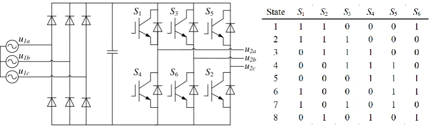
, I is a 2*2 unit matrix. 2.2 Model of ConverterFig 1 shows the topology of a voltage source inverter (VSI) and its valid switching states. This converter prohibits that two switches in each leg are turned on at the same time, therefore the short-circuit switch states should be precluded. Six active vectors are represented by switching state 1-6 and the zero vectors are represented by switching state 7-8. The output voltage 𝒖𝟐in dq reference frame are expressed as
1 1
4 2 2 3 3 -( ) 3 3 1
3
+
2
+
rt j j
p
d p
j
c
e
S S e
S e
u
2u1a
u1b
u1c
S3
S1 S5
S4 S6 S2
u2a
u2b
[image:3.595.85.521.88.218.2]u2c
Fig. 1. The topology of VSI and its valid switching states.
2.3 Cost Function minimization
MMPC strategy is used to make the controlled variables catch up with the corresponding references respectively at the end of the sampling period. The operation of BDFIM is required to satisfy two limitations: (i), the reactive power in PW should be zero; (ii), the speed of the BDFIM should track the reference speed. According to equation (15), the limitation (i) can be obtained by setting
* 1 2
12
d d
i M
(19)
To obtain the limitation (ii), a proportional-integral (PI) regulator is used as shown in Fig. 2. The output of this PI regulator is a reference electromagnetic torque, which can be satisfied with an appropriate 𝑖2𝑞∗ according to
equation (16). The reference value 𝑖2𝑞∗ is
2 *
* 1 1 2
2 2
12 1 12 2 2 1 1
2 3
e q
r d
L L T i
M N M L L
(20) The predictive CW current in next sampling period can be derived from the discrete BDFIM model. To obtain these two limitations, the cost function g is defined as the deviation between the reference CW current and the predictive CW current. And it is expressed as
*
2 *
22d 2d 2q 2q
g i i i i (21)
To obtain a fixed switching frequency, two adjacent active vectors 𝑣𝑗 and 𝑣𝑘, and a zero vector 𝑣0 will be
chosen in each sampling period. Assume that the cost functions of these vectors are gj, gk and g0, respectively.
𝑑𝑗, 𝑑𝑘 and 𝑑0 are the duty cycles of these vectors. 𝑇s is the sampling period. The duty cycles are defined as:
0
0 0
0
0 0
0
0 0
k j
j j k k
j
k s
j j k k
j k
s
j j k k
g g
d T
g g g g g g
g g
d T
g g g g g g
g g
d T
g g g g g g
(22)
Then the new cost function Cost can be defined as
0 0
j j k k
Costd g d g d g (23)
At last, the two active vectors of the minimum cost function value are the optimal solutions and are used to the VSI at the next sampling time.
2.4 Overall control scheme
Speed regulator
Torque transfer
function MMPC
Cost function
+
-BDFIM
abc/dq
PLL
Optical encoder
-abc/dq
Grid 2
r
1
1 1 2 ( ( ) r)
j p p t
e
2dq
i
i
2abc1dq
i i1abc
1
j t
e
1dq
U u1abc
0 0
j j k k
Costd g d g d g
* 2q
i
* 2d
i
*
e T r
*
r
0
V
V
V
0
S S S
1 2
p
p
Reactive power transfer function
Q*
+
(1,2)(2,3)(3,4)(4,5)(5,6)(6,1)
Grid
Fig. 2. Overall control scheme of MMPC strategy for BDFIM.
III.
S
IMULATIONR
ESULTS [image:4.595.92.524.96.392.2]The operation and implementation of MMPC for the BDFIM verified using a simulation in
MATLAB/Simulink. Table I shows simulation parameters of the system.
The CW stator is fed by the VSI. In order to verify the effectiveness of the proposed MMPC scheme in the BDFIM, the reference rotor speed changes from 600 r/min to 800 r/min at t = 10 s when the load torque is 100 N.m. Then, at t = 13.5 s, the load torque changes from 100 N.m to 80 N.m and the reference of rotor speed is still 800 r/min. The reference reactive power is always 0 Var. As shown in the Fig. 3, the results show the waveforms of the rotor speed, the reactive power, the electromagnetic torque and the CW stator current which splits into dq component. At t = 10 s, the motor speed tracks the reference speed effectively with a quick and smooth response, the dynamic response is about 0.4 s. At t = 13.5 s, the electromagnetic torque decreases since the reduction of load torque. The obtained torque response is fast. After a small fluctuation, the variables turn to a steady state.Table I Simulation Parameters
Parameters value Parameters value
Pole pairs of PW (p1) 3 Lr 0.76034H
Pole pairs of CW (p2) 1 R1 0.2680Ω
PW rated phase voltage 220V R2 0.40355Ω
PW rated frequency 50HZ Rr 0.78524Ω
Sampling period 100us M1r 0.04623H
L1 0.04756H M2r 0.70589H
L2 0.71021H
IV.
C
ONCLUSION600 800 1000
-1000 0 1000
100 200 300
9 10 11 12 13 14 15
-50 0 50 100
[r/min]
[Var]
[N.m] Te
Q nr
icd
icq[A] [A]
Time(s) (a)
(b)
(c)
(d)
Fig.3 Simulation results: the reference rotor speed is changed from 600r/min to 800r/min att = 10 s. The load torque is changed from 100 N.m to 80 N.m att = 13.5 s. (a) the rotor speed (b) the reactive power (c) the electromagnetic torque (d) CW dq stator current
V.
R
EFERENCES[1] L.J. Hunt, “A new type of induction motor,” J. Inst. Electr. Eng., vol.39, no.168, pp. 648-677, Jan. 1907.
[2] H. Li and Z. Chen, “Overview of different wind generator systems and their comparisons,” IET Renewable Power Gener., vol. 2, no. 2, pp. 123– 138, 2008
[3] F. Spinato, P.J.Tavner, G. van Bussel, and E. Koutoulakos, “Reliability of wind turbine subassemblies,” IET Renewable Power Gener., vol. 3, no. 4,pp. 387–401, Dec. 2009
[4] H. Polinder, F. van der Pijl, G. de Vilder, and P. Tavner, “Comparison of direct-drive and geared generator concepts for wind turbines,”
IEEETrans. Energy Convers., vol. 21, no. 3, pp. 725–733, Sep. 2006.
[5] S. Shao, A. Ehsan, and R. McMahon, “Vector control of the brushless doubly-fed machine for wind power generation,” in Proc. ICSET, Nov.2008, pp. 322–327
[6] J. Poza, E. Oyarbide, I. Sarasola, I. Sarasola, and M. Rodriguez,, “Vector control design and experimental evaluation for the brushless doubly fed machine,” IET Electr. Power Appl., vol. 3, no. 4, pp. 247–256, Jul. 2009.
[7] I. Sarasola, J. Poza, M. A. Rodriguez, and G. Abad, “Direct torque control design and experimental evaluation for the brushless doubly fed machine,”Energy Convers. Manag., vol. 52, no. 2, pp. 1226–1234, Feb. 2011.
[8] Brassfield WR, Spee R, Habetler TG. Direct torque control for brushless doubly-fed machines. IEEE Trans Ind Appl 1996;32(5):1098– 104.
[9] R. A. McMahon, P. C.Roberts, X.Wang, and P. J. Tavner, “Performance of BDFM as generator and motor,” IEE Proc. Elect. Power Appl., vol. 153, no. 2, pp. 289–299, Mar. 2006.
[10] K. Protsenko and D. Xu, “Modeling and control of brushless doubly-fed induction generators in wind energy applications,” IEEE Trans. PowerElectron., vol. 23, no. 3, pp. 1191–1197, May 2008.
[11] S. Muller, U. Ammann and S. Rees, "New Time-Discrete Modulation Scheme for Matrix Converters," IEEE Trans. Ind. Electron.,vol. 52, pp. 1607-1615, 2005.
[12] P. Cortes, M. P. Kazmierkowski, R. M. Kennel, D. E. Quevedo, and J. Rodriguez, "Predictive Control in Power Electronics and Drives,"
IEEE Trans. Ind. Electron., vol. 55, pp. 4312-4324, 2008.
[13] S. Kouro, P. Cortes, R. Vargas, U. Ammann, and J. Rodriguez, "Model Predictive Control — A Simple and Powerful Method to Control Power Converters," IEEE Trans. Ind. Electron., vol. 56, pp. 1826-1838, 2009.
[14] J. Rodriguez, M. P. Kazmierkowski, J. R. Espinoza, P. Zanchetta, H. Abu-Rub, H. A. Young, and C. A. Rojas, "State of the Art of Finite Control Set Model Predictive Control in Power Electronics," IEEE Trans. Ind. Informat, vol. 9, pp. 1003-1016, 2013.
[15] S. Vazquez, A. Marquez, R. Aguilera, D. Quevedo, J. Leon, and L. Franquelo, “Predictive optimal switching sequence direct power control for grid connected power converters,” Industrial Electronics,IEEE Transactions on, vol. PP, no. 99, pp. 1–1, 2014.
[16] L. Tarisciotti, P. Zanchetta, A. Watson, J. Clare, M. Degano, and S. Bifaretti, “Modulated model predictive control (m2pc) for a 3-phase active rectifier,” pp. 1–1, 2014.
[17] L. Tarisciotti, P. Zanchetta, A. Watson, S. Bifaretti, and J. Clare, “Modulated model predictive control for a seven-level cascaded h-bridge back-to-back converter,” Industrial Electronics, IEEE Transactions on, vol. 61, no. 10, pp. 5375–5383, Oct 2014.