428 | P a g e
IMPLEMENTATION OF CAN DATA COMPRESSION
ALGORITHM
Archana Patil
1, Prof. Mrs. S.N. Rawat
21,2Electronics & Telecommunication Engineering Department,
Savitribai Phule Pune University, (India)
ABSTRACT
A Controller Area Network (CAN bus) is a vehicle oriented bus standard designed to allow microcontrollers and devices to communicate with each other in applications without a host computer. It is a message transfer-based protocol. Controller area network (CAN) is basically designed for multiplexing communication between electronic control units (ECUs) in vehicles and many high-level industrial control applications. Its cost, efficiency, performance and reliability provides higher flexibility in system design. When a CAN bus is overloaded by the increased number of electronic circuit units connected to the CAN bus, the waiting time for low priority CAN messages and the error probability of data transmission are increased. Thus, it is desirable to reduce the CAN data frame size because the time duration for the data transmission is proportional to the CAN frame length. In this paper, a CAN data compression method is designed to reduce or minimize the CAN data frame length. Experimental results show that the transmitted CAN data can be compressed By using an Cortex M3 embedded test board. The proposed algorithm can be used in automobile &multiple applications without any problem.
Keywords: Embedded System, CAN, Data Compression, ECU’s
I.
INTRODUCTION
Controller area network (CAN) is a serial communications protocol which efficiently supports distributed
real-time control with a very high level of security developed in early 1980’s [1]. This serial bus data transmission
system has been successful in many fields of applications due to its high reliability and cost-efficiency.
Nowadays, CAN is one of the most popular bus-oriented protocol for embedded networking applications where
there is a necessity of communication between several embedded 8-bit and 16-bit microcontrollers [3]. CAN
system has gained popularity in embedded machine control applications such as home appliances, industrial
machines and medical equipment which require serial communication between microcontrollers . As the number
of ECUs or sensors connected to the CAN bus increases, so does the bus load. When a CAN bus is overloaded,
it is not easy to transmit low priority CAN messages due to the increased waiting time. In addition, the error
probability of data transmission also increases. If the bus overload causes critical problems in a CAN system, it
is required to set up another CAN network. Instead the bus overload can be reduced by applying a data
compression technique to the CAN data. To reduce the bus load, only the message differences between the
current and the preceding CAN messages can be transmitted based on the observation that CAN data (e.g., fuel
429 | P a g e
maximum value, erroneous message will be transmitted. On the other hand, if the maximum value is set toolarge, the compression efficiency decreases. In this additional header bits are used to avoid sending the
compressed data of zero.
In this paper, we present a CAN message compression method using Cortex M3 embedded board to reduce the
CAN data frame length. In Section II, conventional CAN message compression method is briefly reviewed.
New compression method is proposed in Section III. Performance analysis and implementation of the proposed
algorithm is given in Section IV. Finally, brief conclusions are given in Section V.
1.1 CAN Data Frame Format
The Controller Area Network is a serial communication protocol suited for networking sensors, actuators, and
other nodes in real-time systems. There are two versions of the CAN protocol: CAN 2.0A (standard CAN) with
11 bit identifiers and CAN 2.0B (extended CAN) with 29-bit identifiers. For invehicle communications, only
CAN 2.0A is used, since it provides a sufficient number of identifiers [8]. Fig. 1 shows the format of the CAN
2.0A data frame.
Fig.1.1.1 CAN 2.0A data frame format
The CAN data field can contain up to 8 bytes of data. Whenever the bus is free, any unit may start to transmit
amessage. If two or more units start transmitting messages at the same time, the bus access conflict is resolved
by bitwise arbitration using identifiers. The actual size of the data field is denoted by the data length code
(DLC). CAN uses nonreturnto- zero (NRZ) bit representation with a bit stuffing of length 5. The overall size of
CAN frame is, at most, 135 bits, including all the protocol overheads such as the stuff bits.
Fig.1.1.2 CAN 2.0B data frame format
II. EXISTING CAN DATA COMPRESSION METHOD
430 | P a g e
In existing CAN data compression method, only the differences between the current and the preceding framesare sent. In addition, additional reduction flag code (RFC, or header) is used to avoid sending the compressed
data of 0 [7]. Assume that we try to send 4 signals {P,Q,R,S} and each signal is represented using 16-bits.
Further assume that the range of a difference is ±127. If the signal values of {P,Q,R,S} in the previous frame is
{15, 21, 30, 45} and those values in the current frame is {14, 21, 34, 45}, the difference values are {-1, 0, 4, 0}.
If the difference value of a signal is 0 (e.g. signals Q and S), the corresponding bit of (RFC) is set to zero to
avoid sending the compressed data of zero. Then, “1010” is sent as a RFC value (R) with the actual difference
value {-1, 4}. By the RFC signal, the receiving unit is notified that there is no change in signals Q and S. Table
IV shows the data memory map of existing CAN data compression method.
Bit 7 Bit 6 Bit 5 Bit 4 Bit 3 Bit 2 Bit 1 Bit 0
Byte 0 7 6 5 4 3 2 1 0
Byte 1 15 14 13 12 11 10 9 8
Byte 2 23 22 21 20 19 18 17 16
Byte 3 31 30 29 28 27 26 25 24
Byte 4 39 38 37 36 35 34 33 32
Byte 5 47 46 45 44 43 42 41 40
Byte 6 55 54 53 52 51 50 49 48
Byte 7 63 62 61 60 59 58 57 56
TABLE. 3.1 Memory map of 64 bit data field
In this example, Existing CAN data compression method we can achieve data compression . In existing CAN
data compression method, two message ID’s are used to send CAN messages, original message ID and
compressed message ID (one smaller than the original message ID). For example, if the original message ID is
100 then the compressed message ID is 99. If the difference between the preceding signal and the current signal
is larger than the predicted maximum value, original CAN message is transmitted using the original message ID.
Otherwise, compressed message is transmitted using the compressed message ID. By existing CAN data
compression method, we can avoid sending the compressed data of 0. However, more memory and processing
time are required to deal with increased number of message ID’s.
III. PROPOSED CAN DATA COMPRESSION METHOD
H H
L L
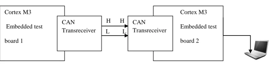
Fig. 4.1.1 Block diagram of proposed CAN data compression method Cortex M3
Embedded test
board 1
Cortex M3
Embedded test
board 2 CAN
Transreceiver
CAN
431 | P a g e
Above figure shows the block diagram of Proposed CAN data compression method. Here two CAN data busesare communicated using Cortex M3 embedded test boards .
In the proposed algorithm, it is not needed to predict the maximum value of the difference in successive CAN
messages. In addition, the 64-bit data field is always assumed to be composed of 8 signals with 8 bits each. This
mechanism eliminates the need for the engineering standard of signal bit length (e.g., Table.3.1.1). We present a
CAN message compression method using compression area selection algorithm and data length code (DLC) to
reduce the CAN frame length. The message compression area is determined by the following algorithm:
After computing the difference value of a signal between current and the preceding frames, each difference
value is represented using 9-bits. The magnitude of the difference is expressed using the most significant 8-bits
(bit 8 to bit1) and the sign is denoted by the least significant bit (bit 0). If the difference is 0 the corresponding
header bit is set to 0. Otherwise, the header bit is set to 1. The header bits are placed at the last column
beginning from the first row in the compression area selection map (Refer to Table 4.1). Then, starting from the
next row, the nonzero difference values are placed from bit 8 to bit 0. Beginning from the leftmost column,
delete a column if every element in the column is zero. The region from the column with the first nonzero
element to the last column is selected as the data compression area.
YES
NO
YES
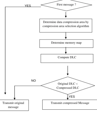
Fig. 4.1.2 Flowchart of proposed compression
First message ?
Determine data compression area by compression area selection algorithm
Determine memory map
Compute DLC
Original DLC < Compressed DLC
Transmit compressed Message Transmit original
432 | P a g e
Signal bit8-bit5 bit 4 bit 3 bit 2 bit 1 bit 0
Header
H0 0
H1 1
H2 1
H3 0
H4 0
H5 1
H6 0
H7 1
B 0…..0 0 1 0 1 1
C 0…..0 0 0 1 0 0
F 0……0 1 0 1 0 1
H 0……0 0 1 1 0 0
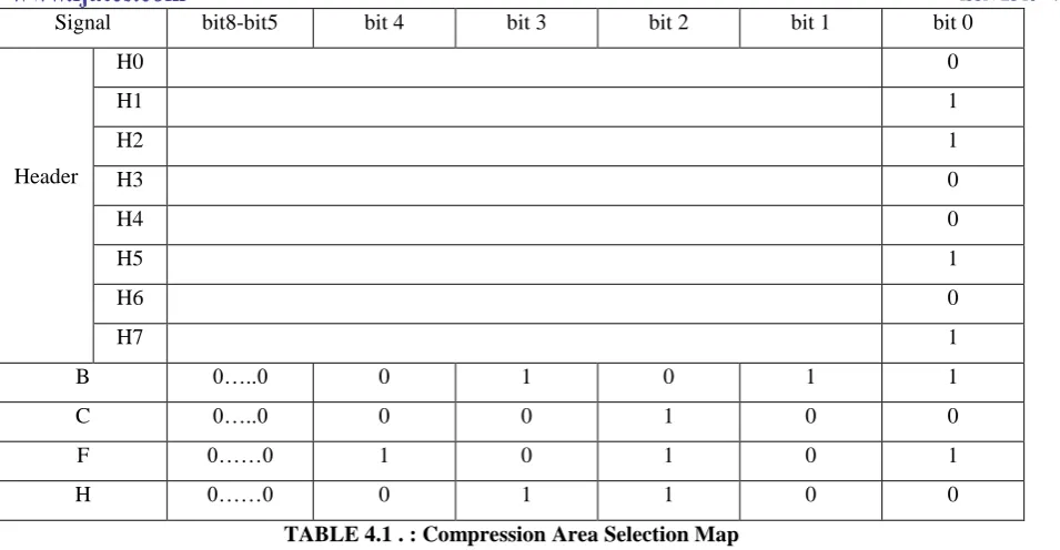
TABLE 4.1 . : Compression Area Selection Map
Assume that we try to send 8 signals {P,Q,R.S,T,U,V,W} with 8 bits each. Also, assume that the signal values
in the previous frame are {5, 15, 58, 0, 15, 50, 0, 34} and those values in the current frame are {5, 10, 60, 0, 15,
40, 0, 40}. Then, the difference values between the current frame and the previous frame are computed and each
difference value is represented using 9 bits (LSB is sign bit). In this example, the difference values are {0, -5, 2,
0, 0, -10, 0, 6}. From the procedure for compression area selection, we can determine the message compression
area (shaded area) as shown in Table V. If the number of the 8-bit signals is less than 8, the compression area
selection map is reduced accordingly. Table VI shows the mapping procedure for the compression area selection
map in Table V. Beginning from the last column in Table V, the data bits are rearranged according to the order .
Compared with 8 bytes of original data before compression, the compressed data can be represented using 4
bytes . For the compressed data, DLC is computed and compared with the original DLC.
If the DLC of the compressed data is smaller than the original DLC, the compressed data is transmitted.
Otherwise, the original data is transmitted. By this way, receiver is informed whether the received CAN frame
was compressed or not since DLC for each ID is predetermined. Thus, the use of two messages ID’s can be
avoided as opposed in existing CAN data compression algorithm. Notice that the size of the memory map is
determined by that of the data compression area. Thus, it is not needed to determine the size of the memory
map in advance. (In conventional compression methods, the size of the memory map is determined by the
predicted maximum difference value.) Consequently, we can avoid the inefficient data compression caused by
the inaccurate prediction of maximum difference values. Fig. 2 shows the flowchart of the proposed CAN data
compression and recovery method. From Fig. 4, it can be seen that CAN data is compressed to 3 or 4 bytes in
most cases by the proposed method under driving situation.
IV. PERFORMANCE ANALYSIS & IMPLEMENTATION
Table VII compares the compression efficiencies of the proposed method of CAN data compression method
obtained by MATLAB simulations of actual CAN signals in c, from Table 5.1, it can be seen that in normal
433 | P a g e
Compression methodNormal Bit Transmission
Transmitted Bits Compression Efficiency
Original 4026880 0%
Proposed 937248 76.73%
TABLE 5.1: Comparison of CAN data compression efficiencies
V. CONCLUSION
In this paper, a CAN message compression method is presented using Cortex M3 embedded test board &
Visual Basic software platform based on data length code (DLC) and compression area selection algorithm to
reduce the CAN frame length and the error probability during the transmission of CAN messages. By the
proposed method, it is not needed to predict the maximum value of the difference in successive CAN messages
in contrast with existing compression method. Also, by the use of DLC, we can determine whether the received
CAN message was compressed or not without using two ID’s as in existing method. By simulations using
actual CAN data, it is shown that the CAN transmission data is further reduced by the proposed method,
compared with conventional methods.
By using an embedded test board, it is shown that CAN data compression can be performed in fractions of
seconds and consequently the proposed algorithm can be used in multiple applications mostly preferred in
automobile applications without any problem.
REFERENCES
[1] CAN Tutorial-Atmel wireless and microcontrollers.
[2] International Journal of Interdisciplinary Telecommunications and Networking (IJITN),2013
[3] Robert Bosch GmbH ,CAN Specification version 2.0. Chuck Powers, Motorola MCTG Multiplex
Applications, April 5, 1995.
[4] M. Desai, S. Rahul, P. Viraj, P. Mayur and R. Samuel, “Controller area network for intelligent vehicular
systems,” Advances in Technology and Engineering(ICATE), 2013 International Conference on, 2013.
[5] Wolfhard Lawrenz, CAN System Engineering: From Theory to Practical Applications. Sringer. 1997.
[6] Automotive networks. CAN in Automation (CiA). http://www.cancia.org/index.php?id=416.
[7] ISO, ISO 11898-1 –Road vehicles – Controller area network (CAN) – part 1: Data link layer and physical
signalling, International Organization for Standardization, 2003.
[8] Yongwook Son, Heeseok Moon, Jaeil Jeong, and Sooyong Lee, “Active CAN data reduction algorithm
for in-vehicle network,” Proceedings of The Korean Society of Automotive Engineers, pp. 1427-1477,
Korea 2006.
[9] G. Leen and D. Heffernan, “Expanding automotive electronic systems” Computer, 35(1): 88-93, Jan
2002.