NETWORK ARCHITECTURAL FRAMEWORK
by
NIRAJ PRABHAVALKAR
A thesis submitted to the
Graduate School-New Brunswick
Rutgers, The State University of New Jersey
in partial fulfillment of the requirements
for the degree of
Master of Science
Graduate Program in Electrical and Computer Engineering
Written under the direction of
And approved by
Professor Manish Parashar
_______________________________________
_______________________________________
_______________________________________
_______________________________________
New Brunswick, New Jersey
October, 200
ABSTRACT OF THE THESIS
The design and evaluation of network services in an active network architectural
framework
by NIRAJ PRABHAVALKAR
Thesis Director:
Professor Manish Parashar
There are an increasing number of applications that require more support from the network nodes
besides the storage and forwarding of bits that the nodes presently provide. These applications
include group communication strategies, scalable network management, provisioning for quality
of service, efficient routing protocols and congestion control mechanisms. Active networks
provide a new networking platform that is flexible and extensible at runtime and supports the
rapid evolution and deployment of networking technologies to suit current needs. They allow the
network nodes to perform application specific computation on the data flowing through them.
Although, with active networking the possibilities for refining current applications and
introducing new ones are tremendous, it is important to demonstrate the performance benefits
accrued from an active networking platform.
Despite research efforts in industry and academia to eliminate network congestion, the problem
continues to persist. Furthermore, a number of applications require a constant bit rate of
transmission while some others tend to ‘grab’ as much network bandwidth as available ignoring
congestion related feedback from the network. We utilize the processing capabilities of active
Traceroute is a popular network utility that discovers the route followed by an IP datagram to
another host. Refinements in accuracy of operation and savings in network resources are achieved
by using an active networking platform to implement traceroute.
This thesis investigates the design of an experimental active network testbed and develops active
services that utilize the underlying network fabric. It makes the following contributions.
The design and implementation of an active network testbed comprising of interconnected
active nodes using object-oriented techniques. In our network model datagrams may select
specific processing at the active nodes from an available set of options thus conforming to a
menu-driven approach.
We have designed and evaluated a congestion control mechanism that aims to limit the
degradation in network performance caused by bandwidth greedy applications. The
mechanism operates by monitoring packet queues to detect a greedy connection. A process of
recursive mobile filtering then controls the identified connection. Specifically, we install a
packet filter for the greedy connection and use active messages to dynamically move the filter
towards the source of the connection. By filtering packets closer to the source, the network
resources are protected from the aggressive flow.
We have implemented an active traceroute utility that achieves considerable savings in time
Table of Contents
ABSTRACT OF THE THESIS... ii
Table of Contents ... iv
List of Illustrations ... viii
Chapter 1... 1
Introduction... 1
1.1 Background and motivation... 3
1.1.1 A lengthy process called ‘Standardization’ ... 3
1.1.2 Application Support ... 4 1.1.3 Technological progress ... 5 1.2 The challenges ... 5 1.2.1 Network security... 6 1.2.3 Interoperability ... 8 1.2.4 Deployment ... 8 1.3 Contributions ... 8 1.4 Thesis Overview ... 9 Chapter 2... 10 Related Work ... 10
2.1 Related Active Network Architectures... 10
2.1.1 Smart Packets ... 10
2.1.2 Active Node Transfer System (ANTS) ... 11
2.1.3 SwitchWare ... 13
2.1.4 CANES (Composable Active Network Elements) ... 14
2.1.4.1 Architecture Overview... 15
2.1.5.1 The NetScript Network and its target applications... 16
2.2 Comparison of architectures ... 17
Chapter 3... 19
RANI Active Network Architecture... 19
3.1 Design overview of RANI (Rutgers Active Network Initiative) ... 19
3.1.1 Components of the RANI active node ... 19
3.1.2 Datagram propagation and ‘tunneling’ ... 20
3.2 Implementation Details ... 20
3.2.1 The RANI node ... 21
3.2.2 Packet format within the node ... 22
3.2.3 Packet movement in the RANI network ... 24
3.2.4 The receive module... 24
3.2.5 The process module ... 25
3.2.6 Transmission module ... 27
3.3 Node operation and configuration... 27
3.4 Summary of network features ... 29
3.5 Limitations of our architecture... 30
Chapter 4... 31 RANI Applications... 31 4.1 Host Reachability ... 31 4.1.1 Ping ... 31 4.1.2 APing ... 31 4.2 Route Discovery... 32 4.2.1 Traceroute ... 32 4.2.2 Atraceroute ... 33 4.2.2.1 Objectives ... 34
4.2.2.2 Operational details... 34
4.2.2.3 Taking a closer look at Atraceroute... 35
4.2.2.4 Implementation of Atraceroute ... 36
4.2.2.5 Features... 37
4.3 Network congestion and unresponsive connections ... 37
4.4 Understanding a congested network... 39
4.5 Background... 39
4.5.1 Introduction ... 39
4.5.2 RED (Random Early Detection) gateways ... 40
4.5.3 ECN (Explicit Congestion Notification) capable gateways ... 41
4.6 Aims of our congestion control strategy... 41
4.7 High level design of algorithm... 42
4.8 Implementation ... 44
4.8.1 Monitoring the active node’s packet queue to isolate a greedy connection ... 44
4.8.2 Controlling the greedy connection... 47
4.8.3 Operation of the mobile filter – The active filter service ... 48
4.8.4 The LGC algorithm... 50
4.8.5 Importance of timing parameters in LGC ... 51
Chapter 5... 53
Experimental Evaluation... 53
5.1 Evaluating the LGC algorithm... 53
5.1.1 Experimental Environment... 53
5.1.2 Source simulation ... 53
5.1.2 Network Topology and active node parameters ... 54
5.1.3 Presenting results ... 55
5.1.5 Experiment 2 – Mobility of the active filter ... 58
5.1.6 Experiment 3 - Multiple bandwidth greedy connections ... 61
5.2 Observations of LGC... 63
Chapter 6... 65
Conclusion and Future Work ... 65
6.1 Summary... 65
6.2 Future Work... 65
References... 67
Appendix A... 69
A.1 Assumptions:... 69
A.2 Comparison of the time complexity for traceroute and Atraceroute ... 69
List of Illustrations
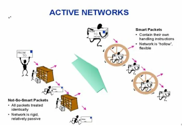
FIGURE 1.1 COMPARING TRADITIONAL NETWORKS WITH ACTIVE NETWORKS... 2
FIGURE 1.2 HOURGLASS MODEL OF TCP/IP NETWORKS... 3
FIGURE 1.3 GENERIC ACTIVE NODE MODEL... 6
FIGURE 3.1 HIGH-LEVEL DESIGN OF THE ACTIVE NODE... 20
FIGURE 3.2 ACTIVE NODE IMPLEMENTATION... 21
FIGURE 3.3 THE RANI NODE... 22
FIGURE 3.4 ACTIVE PACKET FORMAT... 22
FIGURE 3.5 MOVEMENT OF PACKETS IN THE RANI NETWORK... 24
FIGURE 3.6 RECEIVE (RX) MODULE... 25
FIGURE 3.7 PROCESS MODULE... 26
FIGURE 3.8 NODE QUEUE... 27
FIGURE 3.9 GRAPHICAL USER INTERFACE... 28
FIGURE 3.10 SAMPLE NETWORK TOPOLOGY... 29
FIGURE 4.1 OPERATION OF ATRACEROUTE... 34
FIGURE 4.2 FLOWCHART FOR HIGH LEVEL DESIGN OF OUR CONGESTION CONTROL ALGORITHM 44 FIGURE 4.3 PERCENTAGE OF PERMISSIBLE QUEUE OCCUPANCY V/S NUMBER OF CONNECTIONS. 47 FIGURE 4.4 MOBILE FILTERING MECHANISM... 49
FIGURE 5.1 THE ACTIVE NODE AT RUNTIME... 53
FIGURE 5.2 NETWORK TOPOLOGY FOR EXPERIMENT 1 ... 55
FIGURE 5.3 PLOT OF QUEUE SIZE V/S PACKET ARRIVALS FOR NODE 7 ... 56
FIGURE 5.4 PLOT OF QUEUE SIZE V/S PACKET ARRIVALS FOR NON-GREEDY CONNECTIONS... 58
FIGURE 5.5 NETWORKTOPOLOGY FOR EXPERIMENT 2... 59
FIGURE 5.6 PLOT OF QUEUE SIZE V/S PACKET AT NODEI3... 60
FIGURE 5.8 NETWORK TOPOLOGY FOR EXPERIMENT 3... 61
FIGURE 5.9 QUEUE SIZE V/S PACKET ARRIVALS FOR MULTIPLE BANDWIDTH GREEDY SOURCES. 63
FIGURE A.1 COMPARISON OF LINK UTILIZATION... 70
TABLE 2.1 COMPARISON OF ACTIVE NETWORK ARCHITECTURES... 18
Chapter 1
Introduction
An active network may be simplistically viewed as a set of "Active nodes" that perform
customized operations on the data flowing through them. Traditional data networks were
designed with the aim of transferring bits from one end system to another. The transport
mechanism achieved its objectives with minimal computation within the network. In contrast,
active networks allow the network nodes to perform computation on the data passing through
them. In fact, some implementations also allow their users to inject customized programs into the
nodes of the network that may modify, store or redirect the user data flowing through the
network.
An active network is a relatively new concept gaining popularity in 1996. The active networks
program has the goal of producing a new networking platform that is flexible and extensible at
runtime. This platform aims to support the rapid evolution and deployment of networking
technologies to suit current needs and also help in developing services such as group
communication strategies, scalable network management, quality of service, efficient routing
protocols and congestion control mechanisms. The active network architecture supports a finely
tuned degree of control over network services. The packet itself is the basis for describing,
provisioning, or tailoring resources to achieve the delivery and management requirements. One
such architecture makes use of a “Smart Packet” [21] as the basic message unit on the network.
This packet is an agent with its objectives expressed through a portion of the packet called its
"method" -- a set of instructions that can be interpreted consistently by the active nodes through
which it traverses. The network is engineered to allow security, reliability, availability and quality
of service to be tuned at multiple levels of granularity under a wide range of conditions. The
active networks program involves the synthesis of work in programming languages, operating
between traditional networks and active networks. It has been taken from the official DARPA
website [20].
The objectives of this thesis are:
To provide a ‘proof of concept’ for active network technologies. In doing so we wish to
develop an active network testbed, design applications that utilize the added functionality of
the testbed and present relevant results obtained.
To design and build an active network testbed for interconnecting lightweight active nodes.
The testbed must be extensible, user-friendly and should efficiently accommodate traditional
forwarding services.
To implement new network utilities or improve upon existing ones by using the processing
capability of intermediate nodes and to demonstrate the effectiveness of the utilities by
experimental evaluation.
1.1 Background and motivation
The fundamentals for introducing a novel computer networking architecture must be sound. In the
following sections we outline the motivation for developing active network architectures.
1.1.1 A lengthy process called ‘Standardization’
Traditional networking architectures evolve at a slow pace governed by the time taken for
standardization and deployment of new protocols. We need to match this evolution speed with the
speed at which new applications are being introduced into networking. The design philosophy of
TCP/IP networks is based on a layered approach with each layer communicating with its peer
using standardized protocols. A wide variety of high level services such as file transfer (FTP),
E-mail (SMTP, POP) and Hyper-text transfer (HTTP), and low level network technologies such as
ATM, FDDI and Ethernet can be made to inter-operate at the network level by funneling their
functionality’s through the static IP protocol. Thus, IP routers are configured using a hardware
approach with the fixed IP protocol format in mind leading to the hour-glass model of TCP/IP
networks as shown below.
As the Internet grows it is increasingly difficult to maintain, let alone accelerate the pace of
innovation [6]. Every time a sophisticated application emerges or a change in link layer network
technology occurs we need to standardize and deploy new protocols in order to conform to the
interoperable IP layer. Standardization and deployment of such protocols is a lengthy and
time-consuming process taking several years as RSVP (Resource Reservation Protocol) and IGMP
(Internet Group Management Protocol) have proved. By having programmable open nodes and
the ability to deploy programs dynamically into the node engines, network services are decoupled
Figure 1.2 Hourglass model of TCP/IP networks
FTP, HTTP, TCP, UDP
FDDI, Ethernet, ATM
IP (static)
from the underlying hardware. This allows new services to be demand loaded into the
infrastructure. Instead of hard-coding the functions of the network nodes, the execution
environments deployed for the application specific programs needs to be agreed upon so that
innovative ideas can be rapidly inducted over the underlying substrate.
1.1.2 Application Support
There are an increasing number of applications that require more support from the network nodes
besides the storage and forwarding of bits that they presently provide. Some of these applications
are listed below.
The World Wide Web has a client-server design with clients establishing connections with
servers and requesting data from them. Caching "popular" data close to "interested" parties
reduces the latency of the data transfer and also reduces load on the server(s). However,
deploying caches dynamically at strategic locations within the network is a non-trivial task
and cannot be supported without the development of new protocols.
Multicasting takes place with the help of routers having added functionality to route IP
packets to multiple destinations.
Mobility of hosts connected to the Internet requires the presence of mobile proxies in the
network that can re-route traffic to the correct location of the host.
Multimedia applications like video require transcoding mechanisms at strategic locations
within the network to convert high bit-rate streams to lower ones. The transcoder is based on
some data characteristics such as resolution, frame rate, etc.
Installing firewalls in the network at administrative boundaries provides intranet security. The
firewalls are essentially filters that examine transit traffic and allow only conforming traffic
to pass through while blocking other traffic. The manual process of updating firewalls to
enable the use of new applications is an impediment to the adoption of new technology and
A Network utility such as traceroute allows users to discover the route of an IP datagram
from a one node to another. The utility assumes static routes for consecutive datagrams
injected by the source node. We have investigated the impact of active networking
technologies on optimizing the performance of the traceroute utility in terms of reducing
complexity and eliminating the static route assumption.
Many congestion avoidance mechanisms rely on routers and end-hosts to control connections
responsible for causing congestion so as to prevent further degradation of the network.
However, controlling ‘bandwidth greedy connections1’ continues to remain an open problem
in computer communications. In this thesis we will investigate a congestion control strategy
that is aimed at detecting and isolating such connections using active networks.
All the applications described above require some enhanced capabilities within the network to
achieve successful operation. In the absence of architecture support, the present solution consists
of a collection of ad-hoc approaches like installing Web proxies, multicast routers, mobile
proxies, video gateways and firewalls to provide the above services to end-users. The obvious
questions are "Can we have a more generic solution to support a variety of applications, some of
which may not even exist as of today?" and if so "What is the appropriate approach?"
1.1.3 Technological progress
Computationally powerful machines are readily available as desktop PC’s today. We may safely
assume that in the coming years processors will become smaller and faster. The same applies to
network processors such as routers. Advancement in technology will help in developing a generic
network model capable of performing customized computation within the network and not
restricted to the end points as is done today.
1.2 The challenges
The world of computers and communications distinguishes between nodes used for computing
developed as stand alone machines that were subsequently connected by network elements. An
active network tends to narrow the gap between intermediate nodes and end-hosts with the
introduction of programmable open nodes that ‘may’ be injected with code from end-hosts.
Figure 1.3 illustrates a generic active node model and is based on the network model presented in
[14]. It comprises of three principal components; a forwarding engine for storing and forwarding
packets in the network, a transient execution environment for application oriented packet
processing and an accessible storage location for the execution environment. Based on this model
the most notable technical challenges in making the transition from the present Internet to an
active network are network security, evaluating performance benefits, addressing interoperability
and deployment.
1.2.1 Network security
Security issues are critical in active networks especially in implementations that let users load
their own code. The origin of information needs to be authenticated and it must be protected from
modification. Active code may have access to network resources making active networks
particularly susceptible to malicious or defective code that could threaten the operation of the
network. Researchers are finding ways to build networks in a way that will pre-empt defective
programs from harming the network or interfering with other programs and other users. But this
1
Bandwidth greedy connections are defined in chapter 4.
Figure 1.3 Generic active node model
Packet output Packet input Storage Transient Execution Environment Forwarding Engine
approach also leads to a dilemma since we need to carefully restrict the actions of arbitrary code
while providing that very code with the flexibility of network level primitives.
1.2.2 Performance evaluation
The overhead of processing active packets at intermediate nodes in the network makes them fall
behind traditional data networks in terms of latency and throughput. The computation required
within the network may even tend to clog routers leading to network congestion. However,
processing of packets is not needed at every intermediate node within the network since most
applications require specific processing only at strategic locations within the network. Contrary to
popular belief, despite increasing the amount of processing performed within the network,
applications can improve overall system performance. Although throughput (a common network
performance measure) may suffer due to processing overheads in active networks, the application
may benefit on the whole if fewer active packets are needed to achieve the same application
objectives. For example research presented in [37] analyzes the performance of a real time
auction application that uses caching within the network backbone to reduce the load on the
auction server and backbone routers in terms of server load, round trip processing time and
network bandwidth consumption. During periods of heavy load the auction server activates filters
within the network and periodically updates them with the current price of the popular items. The
filtering active nodes are then authorized to reject bids that are lower than the current price. This
active networking protocol helps in distributing the server load, reducing bandwidth consumption
and cutting down on round-trip response time to customers during busy periods. Thus, some
researchers point out that performance should be evaluated in terms of application specific
metrics, which may not be positively correlated with network metrics. The cost of these
performance improvements in Active Networking is in the increased consumption of
computational and storage resources in the network, which may slow down other network traffic
active processing due to the overall reduction in bandwidth utilization and congestion-related
loss.
1.2.3 Interoperability
Packet networks achieve interoperability by standardizing the syntax and semantics of packets.
Internet routers support the agreed IP specifications and perform the same computation on every
packet. In contrast active nodes can perform different computations on the packets flowing
through them. Interoperability must be achieved at a higher level of abstraction. Rather than
fixing the computation performed on the active packet we need to standardize the computational
model consisting of the instruction set and resources available to the active packets. For example,
to achieve cross-platform compatibility, a standard API could be developed to act as a common
programming model for writing the code that is injected into active networks. This would make it
easier to develop new applications as desired and would also reduce the program content of the
active packet.
1.2.4 Deployment
Deploying a new system needs substantial justification along with backward compatibility. To
succeed in the marketplace, proponents must develop applications, both current and future, that
demonstrate a clear advantage as promised without rendering prior networking equipment
useless. In order to strengthen the justification of the active networks program it is required to
demonstrate the capabilities of middleware services2 by developing suitable applications. In this
work we concentrate our efforts in the development of network services on an experimental
testbed.
1.3 Contributions
We have built an active network testbed comprising of interconnected active nodes. By using
object-oriented techniques in the design of our active node we provide extensibility,
2 Middleware services are those that manage system resources, describe message format and support data transformation.
usability and user-friendliness. Further, by creating a separate processing track for active
datagrams, we have ensured minimal impact on applications requiring plain old forwarding
service.
The network utilities we have developed include (a) APing for discovering if a node in the
network is operational and (b) Atraceroute for tracing the path of a datagram in the RANI
active network. We have highlighted the advantages of Atraceroute by testing it on our
network and comparing it with the existing implementation on traditional networks.
We have addressed the problem of limiting the impact of ‘bandwidth greedy connections’ at
congested nodes. We have designed and evaluated an intelligent congestion control
mechanism to detect and counter such connections during periods of severe congestion. In
our implementation we use a packet filter to discard packets belonging to the identified
connection at the congested node and dynamically move the filter towards the source of the
‘greedy’ connection thus protecting network resources from being overwhelmed. We
successfully demonstrated the utility of our mobile filtering mechanism through
experimentation.
1.4 Thesis Overview
Chapter 2 covers related work in which we survey some of the prevalent active network
architectures developed by others. It also includes a comparison of the various active network
architectures. In Chapter 3, we present our active network system architecture highlighting the
goals we have achieved. In Chapter 4 we present the active network services that we have
developed. The chapter begins with a description of our active traceroute and active ping utilities.
Finally, we examine the inadequacies of a popular congestion control strategy with respect to
bandwidth greedy connections and then explain a mobile filtering mechanism for isolating such
connections during periods of high congestion in our active network testbed. Chapter 5 is
dedicated to experimental evaluation of our active filtering mechanism. Chapter 6 draws
Chapter 2
Related Work
With active networking, the network is no longer viewed as a passive mover of bits, but rather as
a more general computation engine: information injected into the network may be modified,
stored or redirected as it is being transported. Obviously such a capability opens up many exciting
possibilities. However, it also raises a number of issues including security, interoperability and
migration strategy. All of these are influenced in large part by the active networking architecture
that defines the interface between the user and the capabilities provided by the network. The
networking architecture adopted has a direct bearing on the utilities and applications that it may
support.
We have developed a simple active network testbed. We utilize the functionality of this testbed
by implementing network utilities and by designing an intelligent congestion control mechanism.
This chapter is devoted to giving a brief overview of the prevailing active network architectural
models. Finally, we compare these architectures and provide the motivation for the design of our
testbed.
2.1 Related Active Network Architectures 2.1.1 Smart Packets
BBN is developing a capability for packets to carry programs that are executed at each node the
packet visits in the network [3]. The programs implement extended diagnostic functionality in
the network. The Smart Packets architecture has the following goals:
Providing a specification for smart packet formats and their encapsulation into some network
data delivery service.
Specification of a high level language, its assembly language, and a compressed encoding
Developing a virtual machine resident in each networking element to provide context for
executing the program within the smart packet.
Developing a secure design
The Smart Packets project is designed to demonstrate that network management is a fruitful target
for exploiting active network technology. Making the programmable environment too rich or
flexible would overload the computing power of the managed node and compromise on security.
To balance flexibility with computing power and security two important decisions were made.
Firstly, there would be no persistent state in the network nodes. Consequently, the programs
carried by the smart packets must be completely self-contained. Even fragmentation of the smart
packet is not permitted. So the programming language used must be able to express meaningful
programs in a short (1Kbyte) length. Secondly, the operating environment must be secure. Also,
the programming language used should avoid dangerous or superfluous features like file system
access or memory management. This goal suggests that the code should be executed within a
virtual machine where only controlled operations are permitted.
2.1.2 Active Node Transfer System (ANTS)
ANTS [8] is part of a continuing research effort of the Software Devices and Systems group at
the MIT Laboratory of Computer Science. An ANTS based network consists of an interconnected
group of nodes that may be connected across the local or wide area by point-to-point or shared
medium channels [7, 37]. In addition to providing IP-style routing and forwarding as the default
network-level service, ANTS allows applications to introduce new protocols into the network.
Applications specify the routines to be executed at the active network nodes that forward their
messages. The various components of the ANTS architecture are presented below.
Protocols and Capsules
: The packets found in traditional networks are replaced by capsules that
refer to the processing to be performed on their behalf at active nodes. Capsule types that shareinformation within the network are grouped into protocols; a protocol provides a service and is
format is to contain an identifier for a protocol and forwarding routine within that protocol. The
identifier is based on a fingerprint of the protocol code. Some forwarding routines are
“well-known” in that they are guaranteed to be available at every active node. Other routines may be
“application-specific”. Typically, they will not reside at every node, but must be transferred to a
node before the first capsules of that type can be processed. Subsequently, capsules belonging to
a particular protocol contain the same identifier and are processed similarly at the active nodes.
Active Nodes: The active nodes execute the capsules of a protocol and maintain protocol state
replace selected routers within the Internet and at participating end nodes. Unlike ordinary
routers, active nodes provide an API for capsule processing routines, and execute those routines
safely by using operating system and language techniques. A major difficulty in designing
programmable networks is to allow nodes to execute user defined programs while preventing
unwanted interactions. The ANTS approach has been to execute protocols within a restricted
environment that limits their access to shared resources. The primitives of the active nodes are -
Environment access; to query the node location, state of links, routing tables, local time and
so forth;
Capsule manipulation; with access to both header fields and payload;
Control operation; to allow capsules to create other capsules and forward, suspend or discard
themselves;
Storage; to manipulate a soft-store of application defined objects that are held for a short
interval.
The capsule format includes a resource limit that functions as a generalized TTL (Time-To-Live)
field. This limit is carried with the capsule and is decremented by nodes as resources are
consumed. Only active nodes may alter this field, and nodes discard capsules when their limit
reaches zero.
Code Distribution Scheme: In ANTS an explicit code distribution mechanism ensures that
where they are needed. This component does not exist in traditional networks and is handled by
the system, not the service programmer. The ANTS implementation couples the transfer of code
with the transfer of data as an in-band function. This approach limits the distribution of code to
where it is needed, while adapting to node and connectivity failures. The code distribution
scheme is suited to flows, i.e., sequences of capsules that follow the same path and require the
same processing.
2.1.3 SwitchWare
SwitchWare [11, 13, 16] is an active networks research effort undertaken at the Penn Department
of Computer and Information Science and Bellcore [18]. Active Networks must balance the
flexibility of a programmable network infrastructure against the safety and security requirements
inherent in sharing that infrastructure. The SwitchWare active network achieves this balance
using three layers, each having a separate language specification. The switchlet language is the
language with which users can access the programmable features of the SwitchWare switch. The
wire language is the form in which the switchlets are moved between switches and the infrastructure language programs the SwitchWare switch. An analogy of a three level language
might be a Java program written by a user, its byte code form, and the C language programs that
comprise the byte code interpreter.
Components of SwitchWare include active packets, their extensions and the secure active router
infrastructure. These are explained below.
Active Packets: An active packet is one that contains both code and data needed to process the
packet in the network. They replace the traditional network packet with a mobile program. The
code part of an active packet provides the control functions of a traditional packet header, but
does so much more flexibly, since it can interact with the environment of the router in a more
complex and customizable way. Similarly, the data in the active packet program replaces the
payload of a traditional packet, but provides a customizable structure that can be used by the
part of its data, looks up the next hop in a routing table, and then forwards the entire packet to the
next hop. At the destination the code delivers the payload part of the data to the application.
Active Extensions: An active extension is some code that may be loaded on a running switch to
alter the processing of future packets. Node-resident extensions form the middle layer of the
architecture. They can be dynamically loaded active extensions or they can be part of the base
functionality of the router. They are not mobile – to communicate with other routers they use
active packets. Thus extensions are base functionality or are dynamic additions rather than
“mobile code”. If the code can only be loaded from a local persistent store, then the extension is
referred to as a local extension. Extensions may make use of other extensions already loaded on
the node; they need not be independent. Extensions reside on the node, e.g., in memory or on
local disk, until they are loaded. Because they are invoked only when needed, there is no inherent
need for the extensions to be lightweight. The key difference between active packets and
extensions is that although extensions may be dynamically loaded across the network, they
execute entirely on a particular node where as active packets are executed at some or all of the
active nodes it passes through.
Secure Active Router Infrastructure: This is the lowest layer of the architecture. While the top
two layers emphasize support for several forms of dynamic flexibility, the lowest layer is
primarily static. The goal of this layer is to provide a secure foundation upon which the other two
layers build. The importance of this is clear, since no matter how much security is assured by the
upper layers, security will be compromised if this layer creates an insecure environment.
2.1.4 CANES (Composable Active Network Elements)
CANES [17] is a research project at Georgia Institute of Technology. In this design, users can
select from an available set of functions to be computed on their data, and can supply parameters
as input to those computations. The available functions are chosen and implemented by the
network service provider, and support specific services; thus users are able to influence the
This approach has some benefits with respect to incremental deployment as well as security and
efficiency: Active Network functions can be individually implemented and thoroughly tested by
the service provider before deployment, and new functions can be added as they are developed.
2.1.4.1 Architecture Overview
The CANES architectural model for active networks takes a menu-based approach in which the
active node supports a fixed set of active functions and the active packets indicate the function(s)
to be invoked and supply parameters to those functions. The basic idea behind this architecture is
the incremental addition of user-controllable functions, where each function is precisely defined
and supports a specific service. The function specifications include:
The identifier associated with the function.
The parameters associated with the function and the method of encoding them in the packet.
The semantics of the function. Ideally, the function semantics would be given in a standard
notation or another notation developed specifically for the purpose. A standard environment,
comprising support services such as private state storage and retrieval, access to shared state
information (e.g. routing tables), message forwarding primitives, etc., would provide a
foundation on which new services could be built.
CANES delegates the addition of a new function to a network node to the network service
provider. As with current networks, once a function is specified, each provider or vendor would
be free to implement the functionality in a manner consistent with the specification. This
approach corresponds roughly to the way new features are deployed in the public switched
telephone network today; users have the option of selecting from a variety of features
implemented by the service provider.
2.1.5 NetScript: A language and Environment for Programmable Networks
NetScript [19] is a programming language and environment for building networked systems. Its
programs are organized as mobile agents that are dispatched to remote systems and executed
systems and to enable their remote programming. NetScript could be used to build packet stream
filters, routers, packet analyzers and multimedia stream processors.
2.1.5.1 The NetScript Network and its target applications
A NetScript network consists of a collection of network nodes (e.g. PCs, switches, routers) each
of which runs one or more NetScript engines. The engine is a software abstraction of a
programmable packet-processing device. Each NetScript engine consists of dataflow components,
called boxes, that process packet-streams that flow through them. Packets flowing through a
NetScript node are processed by successive boxes to perform protocol functions. The system
consists of two components: NetScript, a textual dataflow language for composing
packet-processing protocols and the NetScript Toolkit, a set of Java classes to which the textual language
compiles. The boxes form a reactive system in which data (in the form of packets) flows from one
box to another. Arrival of data at one or more input ports of a box triggers computation within
that box; otherwise the box sleeps until data arrives to trigger it. The box is the central construct
in NetScript and the unit of program composition. A box declaration consists of four parts: the
box name, input port and output port declarations, a declaration of internal boxes and a connect
statement that defines the connections between internal boxes. When a box is loaded at a
NetScript engine, NetScript will instantiate its internal contents and make connections between
these boxes. Typical NetScript boxes do packet header analysis, packet demultipexing, or other
protocol functions. The boxes can be dispatched to remote network engines and dynamically
connected to other boxes that reside there to extend the network with new communication
functions. For example, an IP router implemented in NetScript could be dynamically extended
with firewall functions. Such a router might also be extended to monitor traffic, support content
filtering on the edge of a network domain, or perform load balancing and traffic shaping.
NetScript is useful in applications that process packet-streams.
A key application of NetScript includes the support for distribution of management functions. In
processing their instrumentation data. Other management technologies such as SNMP [23] have
focused on moving data from elements to a management platform where applications processed
this data. NetScript aims to complement these technologies with one that allows a management
platform to dispatch programs (agents) to remote elements. Rather than bringing element data in
real time to applications, applications could be dispatched to process the data right at the
elements. This permits localization of management control loops in managed elements; in
contrast SNMP stretches control loops across the network.
2.2 Comparison of architectures
Principally, there are two ways in which the active network can support processing at
intermediate nodes in the network. In the language-based approach the active datagrams carry
programs that are executed in a suitable environment. Users are allowed to inject code into the
network making the system highly dynamic and flexible. However, special care must be taken to
safeguard the system against malicious users and buggy code. In the menu-based approach the
active node supports a fixed set of services. Designated operators may add new services into the
node. Active datagrams carry a reference to the type of servicing they require. The
implementation details of services are hidden from end user applications. We believe that the
menu-based approach gives a strict administrative control over the services that the network can
offer and provides a secure infrastructure at the cost of reduced dynamism. Thus, we adopt the
menu-driven approach in designing our active network.
The current architectures are in the developmental phase and a consensus on a standard
architecture has still not been reached. Our aim is to develop network services in an active
networking environment and subsequently evaluate them. Hence, we have designed and
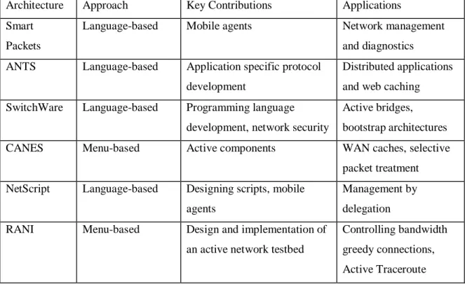
implemented a testbed network (RANI) that is explained in Chapter 3. Table 2.1 shows a
comparison of the active network architectures described in section 2.1. The list of contributions
Architecture Approach Key Contributions Applications Smart
Packets
Language-based Mobile agents Network management
and diagnostics ANTS Language-based Application specific protocol
development
Distributed applications and web caching SwitchWare Language-based Programming language
development, network security
Active bridges, bootstrap architectures
CANES Menu-based Active components WAN caches, selective
packet treatment NetScript Language-based Designing scripts, mobile
agents
Management by delegation RANI Menu-based Design and implementation of
an active network testbed
Controlling bandwidth greedy connections, Active Traceroute
Chapter 3
RANI Active Network Architecture
The Internet Protocol (IP) does not support application oriented processing of datagrams at
intermediate nodes. For an active datagram however the node must process the contents of the
datagram (if it supports active networking) before forwarding it. This chapter describes the design
and implementation of the network architecture. The network testbed is used for experimental
evaluation of our network services.
3.1 Design overview of RANI (Rutgers Active Network Initiative)
The RANI network consists of a number of active nodes connected to each other via virtual links.
For the sake of simplicity, we assume that the virtual links are reliable in delivering datagrams.
Any node can communicate with other nodes in the network by sending datagrams across the
virtual links. Datagrams that do not need active processing are referred to as passive datagrams.
Passive datagrams are simply stored and forwarded similar to traditional network forwarding.
Datagrams that request additional processing at the intermediate nodes in the network are called
active datagrams. Active servicing is requested through a field in the header of the active packet.
Each datagram is considered an atomic element and is processed individually by the active nodes.
3.1.1 Components of the RANI active node
The purpose of the active node is to service the active datagrams and to forward the passive
datagrams towards their destination. Servicing active datagrams may include forwarding them.
Active datagrams are serviced on a best effort basis and may result in a change in the packet’s
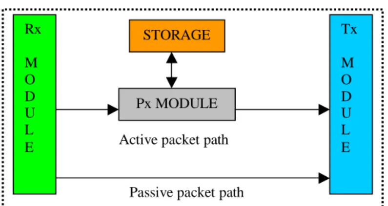
contents. We have divided the various functions of the active node into individiual modules that
interoperate with each other. The Receive (Rx) and Transmit (Tx) modules handle datagram
propagation issues in the network. Active datagrams are serviced in a suitable environment called
the Processing (Px) module. The node resident services and programs are located in the Storage
service. They may also inject passive datagrams that require the traditional forwarding service. In
order ensure speedy delivery of passive datagrams, we have created separate paths for active and
passive datagrams as shown.
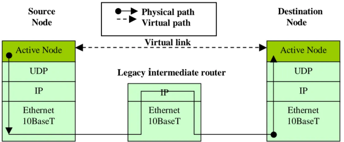
3.1.2 Datagram propagation and ‘tunneling’
We do not expect all nodes in the network to be active nodes. The virtual links that interconnect
active nodes need not consist of a physical connection between the nodes. Virtual links provide a
path between the two nodes that it connects. The physical path corresponding to a virtual link
could traverse across legacy intermediate routers. In effect the virtual link provides a tunnel for
transferring datagrams between active nodes.
To illustrate the use of our active network, let us consider the path of a datagram requesting
service X, from source node S to destination node D. For this example, lets assume that the
network nodes have been configured correctly and a virtual link between node S and node D
exists. At node S, the datagram is sent to the processing module and X is executed on it. S
compares its own address with the destination address of the datagram. On determining that the
datagram has not reached its destination, S sends the datagram across the virtual link towards D.
This action takes place at every active node along the way until it reaches D. At D the datagram is
again serviced and finally delivered to the application.
3.2 Implementation Details
Figure 3.1 High-level design of the active node
Rx M O D U L E Tx M O D U L E STORAGE Px MODULE
Passive packet path Active packet path
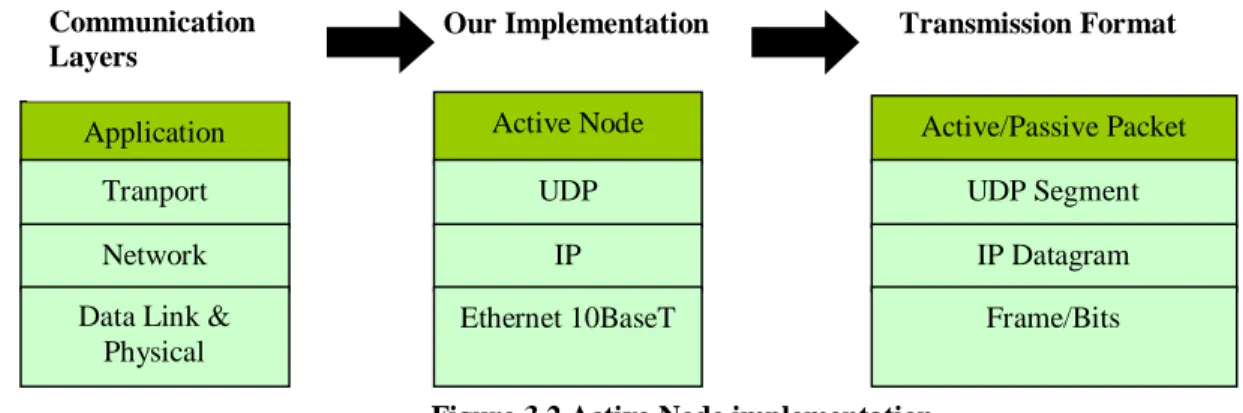
Our active node is implemented in Java (v1.1) as a user space process on the Windows NT
operating system. The node runs at the application layer in the TCP/IP protocol stack. Application
oriented processing of active packets may be required at the end nodes as well as intermediate
nodes in the network. Thus we do not distinguish between intermediate nodes and end nodes.
Virtual links are implemented as a UDP (User Datagram Protocol) socket pair – one socket is
used for receiving datagrams and the other for sending them. Active or passive packets are
created and subsequently injected into the active network via the user interface at the node. These
packets are propagated as UDP segments.
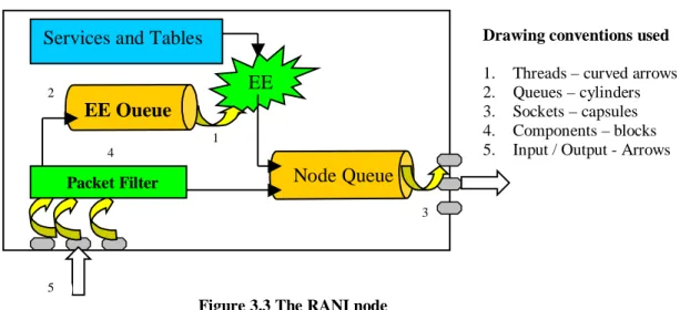
3.2.1 The RANI node
The receive module comprises of UDP receive sockets for incoming datagrams and a packet filter
for separating active and passive packet paths. Each receive socket contains a blocking receive
thread running in an infinite loop to pick up datagrams and deliver them to the packet filter. The
process module comprises of an execution engine (EE) where active packets are serviced. Active
packets are serviced on a first come first served basis by ordering the packets in a FIFO execution
engine queue. An independent EE thread extracts the first packet from the EE queue and
dispatches it to the EE for processing. The EE thread runs in an infinite loop extracting each
packet till the queue empties. The Storage (Sx) module comprises of node resident services and
tables such as the routing table. The Transmission (Tx) module consists of UDP send sockets, a
node queue and a single transmit thread. The node queue is common to all packets (active or
Figure 3.2 Active Node implementation
Application Tranport Network Data Link &
Physical Communication Layers Active Node UDP IP Ethernet 10BaseT Our Implementation Active/Passive Packet UDP Segment IP Datagram Frame/Bits Transmission Format
passive) that need to be forwarded. The transmit thread extracts packets from the node queue and
delivers them to the next hop active node via the virtual links.
3.2.2 Packet format within the node
Before getting into the details of the different components as shown in the above diagram let us
take a look at the packet format within the active node. Datagrams are propagated as UDP
segments in byte array format across virtual links. However once inside the node, the datagram is
converted into either a passive packet or an active packet.
The fields of the active packet are shown below. All the packet fields are in string format and are
initially set at the source node. In comparison to the traditional datagram format, the active packet
has an additional Ack, Act, PrevNode, TL and TOS fields. The packets carry state information in
the TTL and PrevNode fields since these fields must be modified in transit by the active nodes.
The Payload field may be modified in transit depending upon the service requested by the
end-user. We have not provisioned for sequence numbering of packets since at this stage we have
assumed that the network is reliable and have developed network services that deal with
individual active packets.
Figure 3.3 The RANI node
Figure 3.4 Active packet format
SA SP DA DP Ack Act TTL PrevNode TL TOS Payload
Node Queue
EE
Services and Tables
Drawing conventions used1. Threads – curved arrows 2. Queues – cylinders 3. Sockets – capsules 4. Components – blocks 5. Input / Output - Arrows
1 2 5 4 3
EE Queue
Packet FilterSA (Source Address): It is the IPv4 address of the node that injects the packet into the network. SP (Source Port): This field identifies the port number of the virtual link at the source node
through which the packet is injected into the network.
DA (Destination Address): It is the IPv4 address of the destination node for the packet.
DP (Destination Port): This field identifies the port number of the link at the destination node on
which the packet is to be received.
Ack (Acknowledgement): This field is true for acknowledgement packets and is false otherwise. Act (Active): This field is set to true if the packet is active and is false otherwise. It distinguishes
between active and passive packets.
TTL (Time To Live): This field represents an upper bound on the resources that the packet can
consume within the active network. We have kept this resource bound in terms of time. The TTL
field is decremented by active nodes along the way upto the destination node by the amount of
time that the packet exists at the node. If a packet requires excessive processing at a node, it will
reside for a longer duration at the node and correspondingly a larger value will be subtracted from
its TTL resource. An intermediate node discards a packet whose TTL has dropped to zero. The
TTL field is used to discard stale packets by keeping an upper bound on the time that a packet
resides in the network and for calculation of packet round trip time.
PrevNode (Previous Node Visited): This field contains the IPv4 address of the node last visited
by the packet and the port number of the last virtual link on which it traversed. The field is set
just before an active node transmits the packet. Any node in the network can determine the
previous node through which it received a packet by looking up this field. In our present
implementation since we have assumed bi-directional reliable virtual links, this field is unused for
applications developed so far. However, once this assumption is no longer necessarily true in
future implementations, this field will be useful in developing network applications that rely on
TL (TOS Length): This field carries the length in bytes of the TOS field. Keeping in mind the
flexibility of introducing new services, we keep the TOS field to be of variable length.
TOS (Type of Service): The active packet requests a particular service through this field. The
active node provides the service requested on a best-effort basis. For example, if a packet requests
the AtraceRoute service its TOS field is set to AtraceRoute and its TL field is set to 11.
Payload: This field carries the payload of the active or passive packet.
The passive packet has the same format as the active packet with the Active field set to false and
the TL and TOS fields omitted since they do not request any service from the intermediate
network nodes.
3.2.3 Packet movement in the RANI network
Figure 3.5 illustrates the mechanism of injecting packets into the active network from an active
node. The dark line shows the physical path that a packet traverses in our active network. From
the end user application perspective the dotted arrow shows the virtual path that the packet
traverses. The diagram also brings out the concept of ‘tunneling’ packets through legacy
intermediate routers.
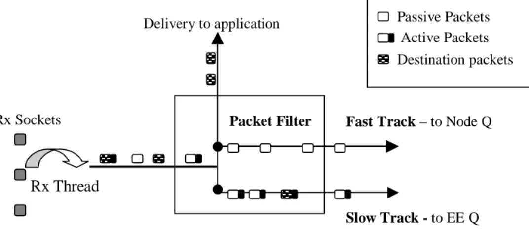
3.2.4 The receive module
Arriving datagrams at the active node are cast into active or passive packets in the packet filter.
An active packet resides at the node till it is completely serviced. Every packet in the node is
subject to a destination check to ascertain if it has reached the destination node. Basically, in the
Figure 3.5 Movement of packets in the RANI network Virtual link Active Node UDP IP Ethernet 10BaseT Active Node UDP IP IP Source Node
Destination Node
Legacy
i
ntermediate router Physical path Virtual path Ethernet 10BaseT Ethernet 10BaseTdestination check, the IP address of the node is compared to the destination address field of the
packet. If the fields match, the test is successful and the packet is delivered to the application. If
the test is unsuccessful the packet is added to the node queue (Node Q) for forwarding. Passive
packets are subjected to a destination check in the packet filter itself. Active packets are directly
dispatched to the execution engine queue (EE Q) by the packet filter. The destination check for
active packets is performed in the process module. By maintaining two separate queues for
servicing (EE Q) and forwarding (Node Q) we create slow and fast tracks for the active and
passive datagrams respectively. If we were to maintain a single queue, the passive packets would
suffer from larger delays due to the longer processing time taken for active packets at the head of
the queue.
Note that when an active packet reaches the destination node it is serviced before being sent to
the application. Passive packets are delivered directly to the application when they reach the
destination node. Figure 3.6 shows the receive module in the RANI node. Here, the spotted
packets are the ones that have reached their destination.
3.2.5 The process module
Active services are stored as loadable classes in the node. They implement the LoadableClass
interface and contain a process method. Active packets are serviced by invoking the process
method of the loaded service class. We maintain a list of all services loaded at the node during its
run time. This list is implemented as a hash table containing the service name as the key and the
Figure 3.6 Receive (Rx) Module
Rx Thread Rx Sockets
Delivery to application
Fast Track – to Node Q
Slow Track - to EE Q Packet Filter
Passive Packets Active Packets Destination packets
class descriptor as the value. Packet servicing occurs in the execution engine. The engine extracts
active packets from the FIFO execution engine queue. The TOS field of the active packet is in the
form of the service name. At the active node, the service name of the active packet is looked up in
the hash table and one of the following cases could occur.
Case 1: The requested service is not found in the hash table. This implies that the service has not
been loaded. The EE attempts to load the service into the node.
Case 1a. If service loading is successful, the hash table is updated and the process routine of the
service class is invoked on the active packet. Henceforth, all successive active packets requesting
this service are directly processed.
Case 1b. In the current implementation, if the service loading is unsuccessful, the packet is
discarded. In future implementations, we could make the node perform traditional forwarding on
active packets that it cannot service. This implies building services that need not require
processing at all intermediate active nodes.
Case 2: The requested service is found in the hash table. This implies that the service has been
previously loaded and so the execution engine directly invokes the process routine of the service
class returned by the hash table, on the active packet.
New services are uploaded to the active node through ‘trusted operators’. A discussion of the
security implications on designating these operators and implementing such a scheme is beyond
the scope of this thesis. Figure 3.7 illustrates the functioning of the process module.
Packet requesting unavailable service EE – Execution Engine Class Loader Stored services Loaded services Process( or ) 2 1 To application To Node Q Dropped packets 1a 1b EE
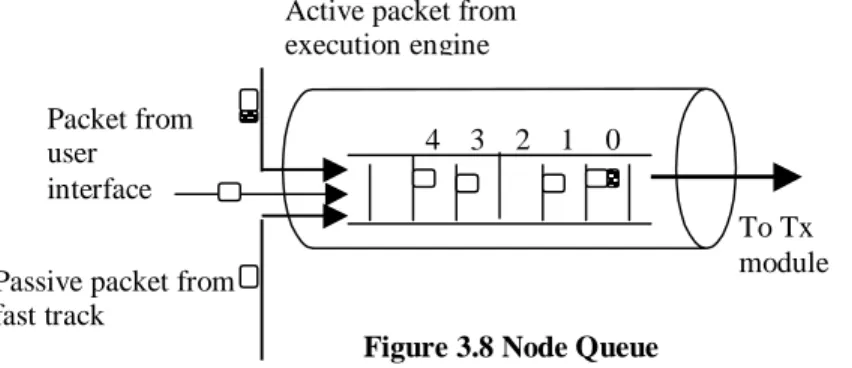
3.2.6 Transmission module
The node queue may receive packets from three sources. The first source is the front-end user
interface (described in section 3.3) through which users may inject packets in the network. The
second source is the receive module which may add passive packets that require forwarding.
Lastly, the execution engine adds active packets that require forwarding to the node queue. The
transmit module extracts packets from the FIFO node queue. It then looks up the routing table
with the destination address and port number of the packet as the key to the table. The table
returns3 the virtual link on which the datagram must be sent. The node then converts the packet
into a UDP datagram in byte array format and sends out the datagram on the returned link. To
handle the special case of looping back (source and destination node fields are the same) of
passive packets in the RANI node, a destination check on the passive packets is performed in the
transmission module.
3.3 Node operation and configuration
We have provided a user-friendly GUI for configuring and operating the active node. Node
operation includes injecting active or passive packets into the network, monitoring the node
queues and testing virtual links for operation. Multiple packets can be injected with the help of a
packet generator that simulates UDP or TCP-like sources. The user can select the number of
packets, the average rate of injection of packets and burst size of the packets4. Node configuration
involves creating (and destroying if necessary) virtual links, managing the routing table and
3
If the routing table returns null, the destination is unreachable and the packet is discarded
4
These parameters are described in Chapter 5
Figure 3.8 Node Queue
To Tx module 4 3 2 1 0
Passive packet from fast track
Active packet from execution engine Packet from
user interface
setting the queue parameters. All nodes in the active network are identified by unique IPv4
addresses. At run time of the active node, virtual links to other nodes are created through the user
interface. Each link successfully created is automatically added to the routing table. The routing
table is implemented as a hashtable containing the destination address and port number as the key
and the virtual link object as the value. The table is automatically updated when new links are
created or existing links are destroyed. We also provide access to manually configure the routing
table for dynamically changing routes in the network. Shown below is an illustration of the user
interface to our active node.
Figure 3.9 Graphical User Interface
Routing table displayed here
This box displays the contents
of the node queue
Active node interface
To explain the construction of routing tables at our active node, consider the following network
topology. Virtual links are labeled VLINK.
In this example, the routing table constructed for node1 and node4 are shown below. We have
assigned arbitrary IP addresses to the active nodes and used arbitrary port numbers for the virtual
links.
NODE 1 NODE 4
Key Value Key Value
Node2 128.6.43.52:2000 VLINK1-2 Node1 128.6.43.20:6000 VLINK1-4
Node3 128.6.30.3:4000 VLINK1-3 Node2 128.6.43.52:2000 VLINK1-4
Node4 128.6.21.18:3000 VLINK1-4 Node3 128.6.30.3:4000 VLINK1-4
Node5 128.6.21.19:3000 VLINK1-4 Node5 128.6.21.19:3000 VLINK4-5
3.4 Summary of network features
The active node provides an environment for communicating with applications, packet
processing and network communications.
The active node does not maintain state or flows unless programmed to do so for a specific
purpose.
Figure 3.10 Sample network topology
Table 3.1 Sample routing table
VLINK4-5 VLINK1-4 VLINK1-3 VLINK1-2
Node5
Node4
Node1
Node2
Node3
The programming model of the network is based on a menu-based approach. End-users may
request network processing through a service-ID field in the active packet. Trusted operators
are allowed to load new services or enhance existing ones, thus minimizing security risks.
At run time, the active node has a user-friendly graphical user interface through which it can
be configured and operated. Also, the active nodes may be restarted and links may be
dynamically changed to reflect a new network topology.
In order to allow multiple packets to be processed simultaneously at the node, entities
interacting with the packet such as queues, tables, threads, links and routines are
synchronized.
Separate tracks are maintained for active and passive packets to speed up traditional
forwarding.
The TTL field in the packet ensures an upper resource limit on the time that a packet may
spend in the network.
3.5 Limitations of our architecture
Firstly, by processing packets within the active network the speed of packet transfer from end to
end is reduced. Although end-applications may benefit from this additional network support even
at reduced packet rates, it is important to maintain a high rate of packet transfer to prevent large
packet queues from building up at the active nodes. Our active node is built at the application
layer in the TCP/IP protocol stack. This makes its operation relatively slow. Secondly since the
aim of this work was to examine active network technologies with respect to network utilities and
congestion control we made simplifying assumptions such as reliable, bi-directional virtual links
and static routing tables. These assumptions prevent real world scenarios from being simulated
for other applications. Lastly, by allowing only trusted operators to load new services into the
active we compromise on the dynamism in enabling new active services. However, these
Chapter 4
RANI Applications
This chapter is divided into two parts. The first part describes the implementation and operation
of RANI network utilities. The second part of this chapter addresses bandwidth greedy
connections in the RANI network.
4.1 Host Reachability
In this section we first describe the implementation of the Ping network utility on traditional IP
networks and then describe its implementation (APing) on the RANI testbed. Aping was the first
active service that we developed as a sanity check for the RANI testbed.
4.1.1 Ping
The word “ping” stands for Packet InterNet Groper. The ping program is often used to test the
reachability of another host on the Internet by sending it echo requests that it must respond to, if
the host is operational [39]. The traditional ping program is one that sends an ICMP (Internet
Control Message Protocol) echo request message to a host and waits for a reply. ICMP messages
are encapsulated in IP datagrams and hence the operation of ICMP does not depend on the
higher-level protocols such as TCP and UDP. Most TCP/IP implementations provide a ping
program and it has proved to be a useful tool.
4.1.2 APing
The operation of APing along with its service routine is provided in this section. The APing
active packet originates from a source node (S) that wishes to discover whether some other target
node (T) in the network is alive. Intermediate nodes forward this active packet towards the target
node. On receiving the active packet, the target node sends back an acknowledgement to the
source. The source node (S) on receiving the acknowledgement displays a message saying that
the queried host is alive. Assuming that the APing service is loaded at an active node, when an
of the APing class is invoked with the active packet as the formal parameter. A line by line
description of the APing.process( ) method is given below.
process ( ActivePacket ) {
if ( ! ActivePacket.destinationReached( ) ); // intermediate node reached {
forward (ActivePacket); // packet forwarded to destination }
else // Destination or Source node reached {
if ( ! ActivePacket.getAck( ); // packet at Destination node {
ActivePacket.sendAck( ); // Create and return an acknowledgement }
else // packet back at Source node {
printSuccess( ) ; // displays reachability message }
} }
4.2 Route Discovery
In this section we first describe the operation of the traceroute utility on traditional
networks. Then we describe its design and implementation on the RANI testbed concluding witha comparison of the two implementations.
4.2.1 Traceroute
Traceroute allows users to discover the route of an IP datagram from a source node to another
node. Traceroute uses the ICMP ‘time exceeded’ message and the TTL (Time To Live) field of
the IP header. The utility requires end nodes to have a programming interface to the TTL field of
an outgoing datagram. Availability of this programming interface to many networked nodes and
sending UDP datagrams to the destination node with the destination port number selected to be of
a large value (>30000) making it highly improbable that an application at the destination is using
that port [38]. The utility begins operation by sending a UDP datagram towards the destination
with a TTL set to 1. The first router to receive the datagram, decrements the TTL to 0,
subsequently discards it and then sends back an ICMP ‘time exceeded’ message to the source.
The source node thus identifies the first router in the path to the destination. Now, traceroute
sends a UDP datagram with a TTL of 2, thus discovering the second router in the path to the
destination node. This process continues till all routers upto the destination node is identified.
When the destination receives a datagram with the TTL of 1, it does not discard it since no further
forwarding is required. Instead, the node attempts to deliver the datagram to the ‘unusually high’
port number which is almost certain to be unused by any application. This results in an ICMP
‘port unreachable’ message being sent back by the destination to the source node. The utility
running at the source node distinguishes between the ICMP ‘time exceeded’ and ‘port
unreachable’ messages to terminate route tracing.
A technical point overlooked above is that for each value of TTL, the utility sends three
datagrams and prints the roundtrip times of the received ICMP messages. If no response is
received within 5 seconds, the utility prints an asterisk and continues operation.
Note:
The traceroute utility assumes that consecutive datagrams from the same source to the same
destination follow the same route.
Time complexity of operation of traceroute is O (n2) where n is the number of hops between
source and destination nodes.
Resource complexity in terms of links traversed is O (n2).
The source node transmits successive IP datagrams towards the destination with incremental
TTL field values till the destination node is reached.
4.2.2.1 Objectives
To accurately determine the forward path of an active pa

![Figure 1.3 illustrates a generic active node model and is based on the network model presented in [14]](https://thumb-us.123doks.com/thumbv2/123dok_us/85107.2509699/15.918.291.682.509.738/figure-illustrates-generic-active-model-based-network-presented.webp)