BNL-103342-2014-CP
Vertical orbit-excursion fixed field alternating
gradient accelerators (V-FFAGs) and 3D cyclotrons
S.J. Brooks
Presented at the 5th International Particle Accelerator Conference (IPAC14)
Dresden, Germany
June 15 – 20, 2014
Collider-Accelerator Department
Brookhaven National Laboratory
U.S. Department of Energy
Office of Science
Notice: This manuscript has been authored by employees of Brookhaven Science Associates, LLC under Contract No. DE-AC02-98CH10886 with the U.S. Department of Energy. The publisher by accepting the manuscript for publication acknowledges that the United States Government retains a non-exclusive, paid-up, irrevocable, world-wide license to publish or reproduce the published form of this manuscript, or allow others to do so, for United States Government purposes.
This preprint is intended for publication in a journal or proceedings. Since changes may be made before publication, it may not be cited or reproduced without the author’s permission.
DISCLAIMER
This report was prepared as an account of work sponsored by an agency of the
United States Government. Neither the United States Government nor any
agency thereof, nor any of their employees, nor any of their contractors,
subcontractors, or their employees, makes any warranty, express or implied, or
assumes any legal liability or responsibility for the accuracy, completeness, or any
third party’s use or the results of such use of any information, apparatus, product,
or process disclosed, or represents that its use would not infringe privately owned
rights. Reference herein to any specific commercial product, process, or service
by trade name, trademark, manufacturer, or otherwise, does not necessarily
constitute or imply its endorsement, recommendation, or favoring by the United
States Government or any agency thereof or its contractors or subcontractors.
The views and opinions of authors expressed herein do not necessarily state or
reflect those of the United States Government or any agency thereof
.
VERTICAL ORBIT-EXCURSION FIXED FIELD ALTERNATING
GRADIENT ACCELERATORS (V-FFAGs) AND 3D CYCLOTRONS
S.J. Brooks
∗, BNL, Upton, NY 11973, USA
Abstract
FFAGs with vertical orbit excursion (VFFAGs) provide a promising alternative design for rings with fixed-field (e.g. superconducting) magnets. They have a vertical magnetic field component that increases with height in the vertical aperture, yielding a skew quadrupole focussing structure. Scaling type VFFAGs have fixed tunes and no intrinsic limi-tation on momentum range; they are also isochronous in the ultra-relativistic limit. Extending isochronism to lower veloc-ities requires a slanted orbit excursion: a three-dimensional analogue of a spiral sector cyclotron from 40 to 1500 MeV is developed, which is flat at low energies and acquires a slope as the protons become relativistic. This provides more stable tunes than a comparable planar cyclotron. Such machines are promising future candidates for nuclear transmutation using high average power CW beams at∼GeV energies.
PURE VERTICAL ORBIT EXCURSION
In a fixed-field ring accelerator such as a cyclotron or FFAG, the closed orbit will move during acceleration to the point where the integrated bending field satisfiesH
Byds=
2πp/q, which closes a full turn at momentump. This as-sumes the acceleration is adiabatic and the optics are linearly stable, in which case the problem is conceptually equivalent to moving a pendulum by its string slowly enough that negli-gible oscillation is acquired. The closed orbit need not move outwards with increasing energy since focussing rather than ‘centrifugal force’ is responsible for its motion.
In VFFAGs, the orbits move upwards with energy andBy
increases withy. The situationBy =B0ek yis particularly interesting since the optics obey a scaling law: an increase of momentump0→p1shifts all particle orbits upwards by
∆y=k1lnpp10. In the interior of a long magnet, this requires
the 2D field shown in figure 1.
Because the scaling law only involves translation, the op-tics and machine tunes are also fixed with energy. A ring based on this was investigated in [1] and achieved alternating gradient focussing using the skew quadrupole component of figure 1’s field by makingB0negative in every second mag-net. Unfortunately this also alternated the sign of the dipole bending field and made the ring magnetically inefficient, much as is the case with scaling FFAGs.
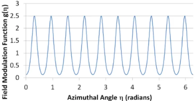
Large edge angles can also be used to obtain alternating gradient focussing in a VFFAG [2] (the edge angles and magnet aperture are vertical), while the body of the magnet continues to bend in the same direction. This improved the magnetic efficiency and gave the ring in figure 2. The scaling law now rotates the orbits about the ring centre slightly as well as translating upwards but the tunes remain fixed.
Figure 1: (left) Ideal exponential scaling VFFAG field in 2D; (centre) how to produce vertical field in a vertical aper-ture with opposing windings; (right) implementation of the VFFAG field with block conductors, from [1].
Figure 2: Perspective view of the 12 GeV proton VFFAG with edge angles from [2].
ISOCHRONOUS MACHINES
The circumferences of orbits in VFFAGs (with or without edge focussing) remain constant with energy. This means that for ultra-relativistic beams, they become isochronous and fixed-frequency RF and CW acceleration can be used. This was the approach suggested in one of the earliest papers discussing VFFAGs [3] for electron acceleration.
The velocity of proton beams changes significantly be-tween pre-injector and ∼GeV energies. Isochronous cy-clotrons conventionally makeD
By
E
= B0γ, giving perfect isochronism if the orbit shapes remain similar and scaled by
β. Unfortunately at high energies, βand the orbit radius are
bounded whileγand the dipole field tend to infinity. The
in-crease in dipole with radius produces a focussing quadrupole proportional to dγ
dβ = βγ
3, which increases faster than the
βγdependence of momentum, so eventually over-focusses the beam. Adding more sectors to get more edge defocussing can give an arbitrarily high maximum energy but for a fixed number of sectors there is always an energy limit.
This over-focussing may be avoided if vertical orbit excur-sion is introduced at higher energies ( [2] §V.B) so that fields for increasingγare no longer so close together. If the orbit
excursion makes an angle ofθwith the horizontal, while the Bfield is vertical and increasing with energy, then there is a
θ/2 rotation of the quadrupole. A vertical excursion propor-tional to lnγwould make the gradient at most proportional toγ, so the optical quadrupole strength would be bounded: this is the scaling VFFAG of the previous section.
3D CYCLOTRON FIELD MODEL
While Maxwellian field models for planar cyclotrons can be found by definingByaty=0 and then using the
tech-nique in [4] to get a Taylor series for the field aty,0, the
corresponding method for a 3D cyclotron is more involved. It is summarised below: see [5] for full mathematical details.
Field Extrapolation from a Curved Surface
IfBis defined at a reference surfacey=Y(x,z), define a shifted magnetic fieldC(x,y,z)=B(x,Y(x,z)+y,z)so that C(x,0,z)is the initial condition. Transforming Maxwell’s equations in free space to act onCgives
∂yC= 1 Yx 0 −Yx 1 −Yz 0 Yz 1 −1 0 ∂x 0 −∂x 0 −∂z 0 ∂z 0 C,
whereYxandYzare partial derivatives ofY. There is also
a consistency condition∂zCx−∂xCz =Yz∂xCy−Yx∂zCy,
which was not a difficulty whenY = 0 since it could be satisfied by settingBx=Bz =0 on the mid-plane, but now
has a non-trivial effect. It is satisfied ( [5] §3.4) by adding particularBxand Bz components to the initial condition,
determined by integrating the desiredByalong a line from
the centre of the cyclotron. The field is evaluated via the truncated Taylor expansion
BN(x,y,z)= N X n=0 (y−Y(x,z))n n! ∂ n yC(x,0,z),
which is analogous to the planar method except the form of
∂n
yCis now extremely complicated and for this paper was
evaluated using a computer algebra system.
Spiral Sector Fields
Projecting the shape of the cyclotron onto thex-zplane, the sectors make a constant edge angleθe with the radial
direction. In polar coordinates(r, θ), a new angular coor-dinateη = θ−(tanθe)lnrhas the property that lines of
constantηare parallel to the sector edges. Thus the vertical
field on the cyclotron’s reference plane is set to be By(x,Y(x,z),z)=B0γg(η)= p B0
1−(r/R)2 g(η),
whereγis the ideal value based on the radiusr= √x2+z2 and the asymptotic radiusRcorresponding toβ=1. For the
orbits to close, the valueB0 =mc/qRmust be chosen for the particle of interest and the functiong(η), which determines the azimuthal field flutter, should satisfyhg(η)i=1.
In this paper, g(η) is a sum of functions of the form ±tanh((η −ηn)/θf) for sector edge locations ηn that is
rescaled to average unity. The valueθf determines the fringe
field extent. The ‘packing factor’ or proportion of ring taken by the interior of the sectors can also be varied.
Magnet Windings
It is envisioned that the field can be produced in practice by superconducting windings at y =Y(x,z)±∆y above
and below the midplane. This is already a standard arrange-ment for producing Byin wide-aperture superconducting
dipoles (iron may also be used whenBydominates). The
windings needed for transverse fields have currents that run in opposing directions on either side of the plane rather than symmetrically, like the centre part of figure 1. Once these current components are added together, winding configura-tions for above and below should result.
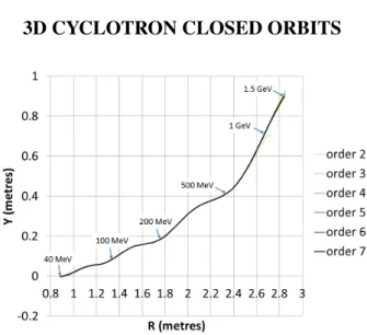
3D CYCLOTRON CLOSED ORBITS
Figure 3: Closed orbit start points in the 3D cyclotron, for magnetic fields evaluated to orders 2 through 7.
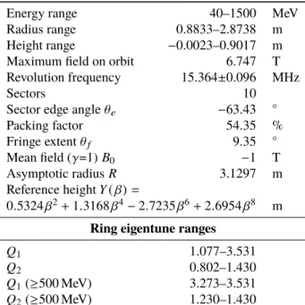
Closed orbits for the 3D cyclotron specified in table 1 were calculated using the Muon1 code ( [6], chapter 2). The reference height is given as a function of the ideal β=r/R and the azimuthal modulation resulting from the large fringe extent is shown in figure 4. The orbit positions shown in figure 3 are at the entrance and exit of a 36◦wedge that does not follow the spiral shape, hence the undulations. Figure 13 shows a three-dimensional view of the orbits.
Table 1: Parameters of the 3D Cyclotron
Energy range 40–1500 MeV
Radius range 0.8833–2.8738 m Height range −0.0023–0.9017 m Maximum field on orbit 6.747 T Revolution frequency 15.364±0.096 MHz
Sectors 10
Sector edge angleθe −63.43 ◦
Packing factor 54.35 % Fringe extentθf 9.35 ◦ Mean field (γ=1)B0 −1 T Asymptotic radiusR 3.1297 m Reference heightY(β)= 0.5324β2+1.3168β4−2.7235β6+2.6954β8 m Ring eigentune ranges
Q1 1.077–3.531
Q2 0.802–1.430
Q1(≥500 MeV) 3.273–3.531
Q2(≥500 MeV) 1.230–1.430
Br components in the sector edge fields cause vertical
undulations in the orbits. The high energy orbits are also sig-nificantly below the theoretical locationr= βR,Y =Y(β), as shown in figure 5. This is not yet understood and specify-ing a different initial condition may better align the orbits with the reference surface. The large offset means many terms in the Taylor expansion are needed for convergence, which is why figure 3 and others show the results converging with each order. Higher orders take exponentially longer to calculate in the current implementation of the field model, limiting how far the series can go.
Figure 5: Motion of closed orbit (blue loops) relative to theoretical location on the reference plane (green crosses).
The time of flight shown in figure 6 varies slightly (±0.62%) because the orbits are not exactly similar in shape.
It is hoped that adding a small polynomial δf(γ) to the overallB0γfield dependence can fine-tune the orbit radii in
Figure 6: Time of flight per sector of the 3D cyclotron.
Figure 7: Maximum|B|encountered in the 3D cyclotron.
future. The largest fields encountered at the closed orbits for each energy are shown in figure 7.
Linear Optics
The tunes per sector of the machine are shown in figure 8; since the dynamics is coupled, these are ‘eigentunes’ derived from eigenvalues of the transfer matrix. Above 500 MeV they are reasonably flat, nearly avoiding the half-integer reso-nances of the 10 sector ring out to 1.5 GeV. The edge angleθe
was not allowed to vary with energy, which is an important parameter in controlling the tunes in such machines as the TRIUMF cyclotron, so it is expected that better behaviour can be obtained once this is optimised.
Figure 9 shows the two focussing ‘eigenplanes’ varying with energy, one associated with each eigentune. The be-haviour changes from orthogonal planes to skew and back, before ending with a somewhat coupled skew system.
At present, estimation of dynamic aperture is difficult since repeated tracking through the fields amplifies non-symplectic behaviour from the truncated series.
Figure 9: The two linear focussing eigenplanes projected intox-yspace for various 3D cyclotron closed orbits.
COMPARISON TO 2D CYCLOTRON
Table 2: Parameters of the Planar Cyclotron Energy range 40–1500 MeV Radius range 0.8684–2.9032 m Maximum field on orbit 6.690 T Revolution frequency 15.323±0.017 MHz
Sectors 10
Sector edge angleθe −63.43 ◦
Packing factor 10.21 %
Fringe extentθf 7.04 ◦
Mean field (γ=1)B0 −1 T Asymptotic radiusR 3.1297 m
Ring tune ranges
Qx 1.096–2.864
Qy 0.551–2.594
Qx(≥500 MeV) 1.621–2.864
Qy(≥500 MeV) 0.551–2.280
During optimisation studies, entirely planar cyclotrons capable of 1.5 GeV were also found. The cyclotron speci-fied in table 2 with azimuthal variation shown in figure 10 produced the orbits shown in figure 11.
Figure 10: Field modulation in the planar cyclotron.
Figure 11: Closed orbits in the planar cyclotron.
Figure 12: Sector tune variation in the planar cyclotron. The tunes of this machine (figure 12) behave very differ-ently to the 3D cyclotron. Qxmust always increase with
energy due to the quadrupole from the planar isochronous field, eventually reaching the edge of the stable area with Qy=0. Many half-integer ring resonances are crossed.
Figure 13: Geometry and closed orbits of the 3D cyclotron in plan view (left) and various perspective views, showing orbit undulation and downward offset of orbits from the reference plane (centre right).
CONCLUSION AND FUTURE WORK
3D cyclotrons promise cyclotron-like performance above 1 GeV, where there are high cross sections for spallation reactions. They were first successfully tracked only a month before IPAC’14, so many tasks still need to be addressed:
• Better alignment between the reference plane and the orbits, giving better convergence in the field model and enabling dynamic aperture calculations;
• Field adjustments to improve isochronism from the current±0.62% variation;
• Varyθewith energy to improve tune control;
• Make space for RF by using fewer sectors and/or more field-free space between sectors;
• Find an example superconducting winding scheme; • Build scaled-down electron model of the 3D cyclotron.
REFERENCES
[1] Vertical Orbit Excursion FFAGs, S.J. Brooks, Proc. HB2010. [2] Vertical Orbit Excursion Fixed Field Alternating Gradient Accelerators, S.J. Brooks, Phys. Rev. ST Accel. Beams16, 084001 (2013).
[3] Accelerators with Vertically Increasing Field, J. Teichmann, Atomnaya Énergiya, Vol.12, No.6, pp.475–482 (1962). [4] Extending the Energy Range of 50 Hz Proton FFAGs,
S.J. Brooks, Proc. PAC’09.
[5] Extrapolation of Magnetic Fields from a Curved Surface, S.J. Brooks, note available fromhttp://stephenbrooks.
org/ap/report/2014-2/offsurface.pdf(2014).
[6] Muon Capture Schemes for the Neutrino Factory, Stephen
Brooks, D.Phil., University of Oxford, available fromhttp:
![Figure 2: Perspective view of the 12 GeV proton VFFAG with edge angles from [2].](https://thumb-us.123doks.com/thumbv2/123dok_us/9950587.2889582/3.892.462.806.512.567/figure-perspective-view-gev-proton-vffag-edge-angles.webp)