Scholars' Mine
Scholars' Mine
Doctoral Dissertations Student Theses and Dissertations
2012
Real-time localization using received signal strength
Real-time localization using received signal strength
Mohammed Rana BasheerFollow this and additional works at: https://scholarsmine.mst.edu/doctoral_dissertations Part of the Computer Engineering Commons
Department: Electrical and Computer Engineering Department: Electrical and Computer Engineering Recommended Citation
Recommended Citation
Basheer, Mohammed Rana, "Real-time localization using received signal strength" (2012). Doctoral Dissertations. 2426.
https://scholarsmine.mst.edu/doctoral_dissertations/2426
This thesis is brought to you by Scholars' Mine, a service of the Missouri S&T Library and Learning Resources. This work is protected by U. S. Copyright Law. Unauthorized use including reproduction for redistribution requires the permission of the copyright holder. For more information, please contact [email protected].
REAL-TIME LOCALIZATION USING RECEIVED SIGNAL STRENGTH
by
MOHAMMED RANA BASHEER
A DISSERTATION
Presented to the Faculty of the Graduate School of the MISSOURI UNIVERSITY OF SCIENCE AND TECHNOLOGY
In Partial Fulfillment of the Requirements for the Degree
DOCTOR OF PHILOSOPHY in
COMPUTER ENGINEERING
2012 Approved by
Jagannathan Sarangapani, Advisor Sanjay Madria
Reza Zoughi Daryl G. Beetner
R. Joe Stanley Al Salour
iii
PUBLICATION DISSERTATION OPTION
This dissertation would consist of the following five articles:
Paper 1, M.R. Basheer, and S. Jagannathan, "Enhancing Localization Accuracy in an RSSI Based RTLS Using R-Factor and Diversity Combination", has been submitted to the International Journal of Wireless Information Networks.
Paper 2, M.R. Basheer, and S. Jagannathan, "Receiver Placement Using Delaunay Refinement-based Triangulation in an RSSI Based Localization" has been revised and re-submitted to IEEE/ACM Transactions on Networking,
Paper 3, M.R. Basheer, and S. Jagannathan, "Localization of RFID Tags using Stochastic Tunneling", accepted in the IEEE Transactions on Mobile Computing
Paper 4, M.R. Basheer, and S. Jagannathan, "Localization and Tracking of Objects Using Cross-Correlation of Shadow Fading Noise", has been revised and resubmitted to the IEEE Transactions on Mobile Computing.
Paper 5, M.R. Basheer, and S. Jagannathan, "Placement of Receivers for Shadow Fading Cross-Correlation Based Localization", has been submitted to the IEEE Transactions on Mobile Computing.
iv
ABSTRACT
Locating and tracking assets in an indoor environment is a fundamental requirement for several applications which include for instance network enabled manufacturing. However, translating time of flight-based GPS technique for indoor solutions has proven very costly and inaccurate primarily due to the need for high resolution clocks and the non-availability of reliable line of sight condition between the transmitter and receiver. In this dissertation, localization and tracking of wireless devices using radio signal strength (RSS) measurements in an indoor environment is undertaken. This dissertation is presented in the form of five papers.
The first two papers deal with localization and placement of receivers using a range-based method where the Friis transmission equation is used to relate the variation of the power with radial distance separation between the transmitter and receiver. The third paper introduces the cross correlation based localization methodology. Additionally, this paper also presents localization of passive RFID tags operating at 13.56MHz frequency or less by measuring the cross-correlation in multipath noise from the backscattered signals. The fourth paper extends the cross-correlation based localization algorithm to wireless devices operating at 2.4GHz by exploiting shadow fading cross-correlation. The final paper explores the placement of receivers in the target environment to ensure certain level of localization accuracy under cross-correlation based method. The effectiveness of our localization methodology is demonstrated experimentally by using IEEE 802.15.4 radios operating in fading noise rich environment such as an indoor mall and in a laboratory facility of Missouri University of Science and Technology. Analytical performance guarantees are also included for these methods in the dissertation.
v
ACKNOWLEDGEMENTS
I would like to thank my advisor Dr. Jagannathan Sarangapani for guiding me and providing me the motivation and vision to complete this dissertation. In addition, I would like to thank my parents Prof. E. Basheer and Asuma Beevi for installing in me the desire to seek out for knowledge how hard and far I have to struggle to get it.
vi
TABLE OF CONTENTS
Page
PUBLICATION DISSERTATION OPTION ... iii
ABSTRACT ... iv
ACKNOWLEDGEMENTS ...v
LIST OF ILLUSTRATIONS ...x
LIST OF TABLES ... xiii
SECTION 1. INTRODUCTION ...1
1.1 ORGANIZATION OF THE DISSERTATION ...5
1.2 CONTRIBUTIONS OF THE DISSERTATION ...10
1.3 REFERENCES ...11
PAPERS I. ENHANCING LOCALIZATION ACCURACY IN AN RSSI BASED RTLS USING R-FACTOR AND DIVERSITY COMBINATION ...13
Abstract ...13
1. INTRODUCTION ...14
2. MEAN SQUARE ERROR OF RADIAL DISTANCE ESTIMATE ...17
3. R-FACTOR ...22
4. DIVERSITY AND R-FACTOR ...25
5. RESULTS AND ANALYSIS ...34
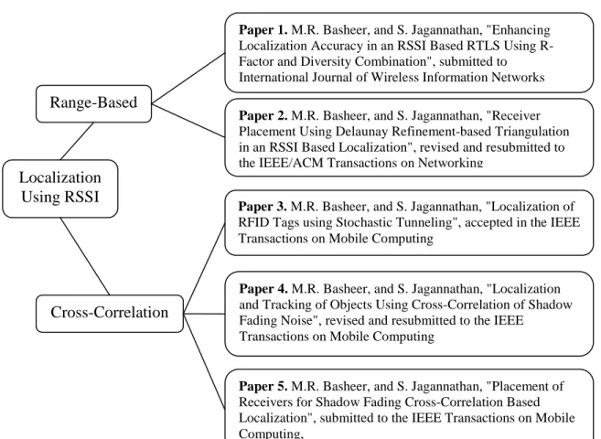
5.1 RADIAL DISTANCE ESTIMATION ERROR WITH DISTANCE ...34
5.2 USING R-FACTOR TO DETECT NLOS ...35
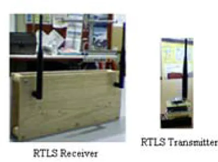
5.3 LOCALIZATION EXPERIMENTS ...37
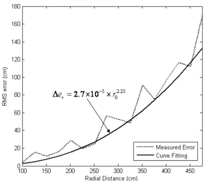
5.3.1 TEST-BED AND IMPLEMENTATION ...37
5.3.2 LOCATION DETERMINATION ALGORITHM ...38
5.3.3 LOCALIZATION RESULTS AND ANALYSIS ...38
6. CONCLUSIONS ...41
vii
II. RECEIVER PLACEMENT USING DELAUNAY REFINEMENT
BASED TRIANGULATION IN AN RSS BASED LOCALIZATION ...44
Abstract ...43
1. INTRODUCTION ...46
2. PROBLEM STATEMENT ...51
3. BACKGROUND ...51
3.1 WIRELESS PROPAGATION MODEL...51
3.2 CONSTRAINED WEIGHTED LEAST SQUARES...53
4. LOCATION ESTIMATION ERROR ...54
5. RECEIVER PLACEMENT QUALITY METRIC ...57
6. UNCONSTRAINED RECEIVER PLACEMENT GEOMETRY ...58
7. TESSELLATING THE WORKSPACE USING TRIANGLES...62
8. RESULTS AND ANALYSIS ...68
8.1 RECEIVER PLACEMENT USING DELAUNAY REFINEMENT ...69
8.2 LOCALIZATION EXPERIMENT ...72
8.3 SIMULATIONS ...76
8.3.1 RSS SAMPLE COUNT VS. ϵU ...76
8.3.2 RECEIVER COUNT FROM DR AND OPTIMAL PLACEMENT...77
9. CONCLUSIONS...79
REFERENCES ...80
III.LOCALIZATION OF RFID TAGS USING STOCHASTIC TUNNELING ...82
Abstract ...82 1. INTRODUCTION ...83 2. PROBLEM STATEMENT ...88 3. BACKGROUND ...89 3.1 VON-MISES DISTRIBUTION ...89 3.2 COMPOSITE LIKELIHOOD ...90
4. LOCALIZATION FROM BACKSCATTERED RSSI ...91
4.1 RSSI CORRELATION PARAMETERS ...91
4.2 LIKELIHOOD FUNCTION FOR RADIAL DISTANCE ESTIMATION ...95
viii
4.3 STOCHASTIC CONSTRAINED OPTIMIZATION ...102
4.4 ANCHOR NODE PLACEMENT...104
5. LOCUST ALGORITHM ...105
6. RESULTS AND ANALYSIS ...107
7. CONCLUSIONS...112
REFERENCES ...112
APPENDIX ...115
IV.LOCALIZATION AND TRACKING OF OBJECTS USING CROSS-CORRELATION OF SHADOW FADING NOISE ...127
Abstract ...127
1. INTRODUCTION ...128
2. LOCALIZATION PROBLEM AND RELEVANT BACKGROUND INFORMATION...134
2.1 PROBLEM STATEMENT ...134
2.2 INDOOR WIRELESS PROPAGATION MODEL ...135
2.3 COPULA FUNCTIONS ...138
2.4 𝛼 - DIVERGENCE ...139
3. LOCALIZATION FROM SHADOW FADING RESIDUALS ...140
3.1 SHADOW FADING NOISE EXTRACTION FROM RSSI ...141
3.2 SHADOW FADING CORRELATION COEFFICIENT ...143
3.3 STUDENT-T COPULA BASED SHADOW FADING CROSS- CORRELATION LIKELIHOOD FUNCTION ...145
4. MOBILE TRANSMITTER TRACKING ...147
4.1 SPEED ESTIMATION USING 𝜶 - DIVERGENCE ...147
4.2 BAYESIAN FILTERING OF A MOBILE TRANSMITTER USING STUDENT-T COPULA LIKELIHOOD ...149
5. LOCALIZATION AND TRACKING ALGORITHM ...152
6. RESULTS AND ANALYSIS ...154
6.1 SHADOW FADING 𝝆 SIMULATION ...155
6.2 TRANSMITTER LOCALIZATION IN A FOOD COURT ...158
6.3 TRACKING EXPERIMENT...161
7. CONCLUSIONS...166
ix
APPENDIX ...169
V. PLACEMENT OF RECEIVERS FOR SHADOW FADING CROSS-CORRELATION BASED LOCALIZATION ...176
Abstract ...176
1. INTRODUCTION ...177
2. BACKGROUND ...182
2.1 CRAMER RAO LOWER BOUND ...182
2.2 INDOOR SHADOW FADING CORRELATION MODEL ...183
2.3 COMPOSITE LIKELIHOOD ...185
3. RECEIVER PLACEMENT UNDER CROSS-CORRELATION OF SHADOW FADING ...187
3.1 OPTIMAL UNCONSTRAINED RECEIVER PLACEMENT FOR COMPLETE LOCALIZATION COVERAGE ...189
3.2 RECEIVER PLACEMENT NEAR WORKSPACE BOUNDARY ...192
3.3 METRIC FOR EVALUATING RECEIVER PLACEMENT UNDER TRANSMITTER LOCALIZAITON CROSS-CORRELATION OF SHADOW FADING RESIDUALS ...195
4. RECEIVER PLACEMENT ALGORITHM ...199
5. RESULTS AND ANALYSIS ...201
5.1 RECEIVER COUNT VS. COMMUNICATION RANGE ...202
5.2 LOCALIZATION ACCURACY VS. RECEIVER PLACEMENT...203
6. CONCLUSIONS...206
REFERENCES ...206
SECTION 2. CONCLUSIONS AND FUTURE WORK ...209
x
LIST OF ILLUSTRATIONS
Figure Page INTRODUCTION 1.1 Dissertation outline ...6 PAPER I 1. R-factor of a localization receiver’s diversity combination using SC, Avg. & RMS ...292. R-factor plot of diversity combination for a receiver under NLoS condition using SC, Avg. & RMS ...32
3. Estimation RMS error variation with actual radial distance ...35
4. Variation of R-Factor at various angles ...36
5. MST RTLS system ...37
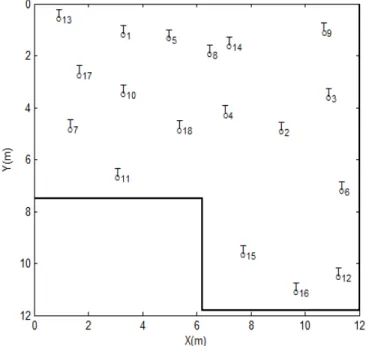
6. Floor Plan of ERL 114 with receivers numbered R1 to R8 marked with circles ...39
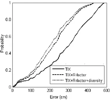
7. CDF of localization error ...40
PAPER II 1. An 𝑀 = 7 receiver layout arranged in the form of a polygon with receivers placed at its vertices...49
2. Location coverage at a receiver ...61
3. Local feature size ...65
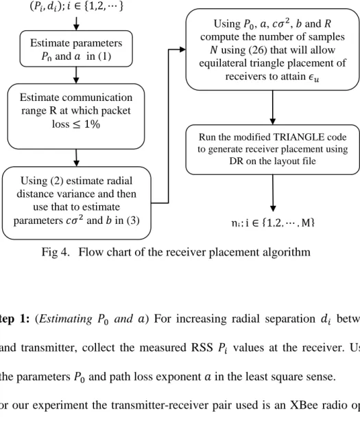
4. Flow chart of the receiver placement algorithm ...69
5. RSS and radial distance variance with actual radial distance ...71
6. Comparison of the receiver layout using DR and DT ...73
7. Test points for localization accuracy ...74
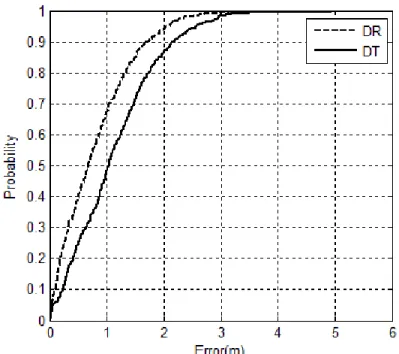
8. CDF of localization error ...75
9. RSS sample count vs. localization error threshold 𝜖𝑢 ...76
xi
PAPER III
1. RFID tags in a freight container...84
2. Tags in a workspace with radial distance shown in dotted lines ...100
3. Possible set of triangles used as constraints for (16) ...101
4. Terrain of (16) at various frequencies under NLoS conditions ...103
5. Tunneling effect on cost function ...104
6. Flow chart of the proposed localization scheme ...106
7. CDF of localization error at 20MHz ...108
8. Scattering of radio waves by objects in the workspace before reaching the RFID tags 1 and 2 ...115
PAPER IV 1. GBSBEM Wireless Channel Model ...135
2. Overlapping of scattering regions causing cross-correlation in shadow fading ...143
3. Tracking a mobile transmitter ...150
4. Flow chart of mobile transmitter tracking ...153
5. Correlation coefficient vs. radial separation between receivers ...156
6. Correlation coefficient vs. radial separation between transmitter-receiver ..157
7. Effect of 𝜏𝑚and 𝜔 on 𝜌 ...158
8. Layout of the food court area used for localization experiment with dark lines showing the physical boundary walls ...159
9. Top view of ERL 114 with receiver positions shown...162
10. Tracked points from INS, 𝛼-divergence and copula smoothing methods ....163
11. RMSE from INS, 𝛼-divergence and copula smoothing methods ...164
12. Velocity estimates from INS and 𝛼-divergence ...165
xii
PAPER V
1. GBSBEM wireless channel model...184 2. Overlapping of scattering regions causing correlation in shadow fading
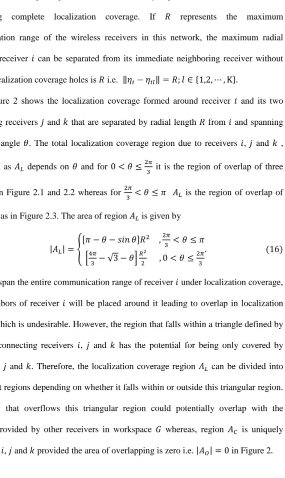
residuals ...185 3. Location coverage by a receiver and its direct neighbors ...191 4. Location coverage holes near the boundary of a perimeter wall ...193 5. Localization coverage within the triangle defined by joining 𝜂𝑖, 𝜂𝑗
and 𝜂𝑘 ...194 6. Initial stages of receiver placement algorithm within a workspace ...200 7. Receiver placement localization coverage and error analysis within a workspace ...201 8. Receiver count vs. communication range ...203 9. Receiver placement over sample workspace ...204
xiii
LIST OF TABLES
Table Page
PAPER I
1. SUMMARY OF LOCALIZATION ERROR LEVELS ...41 PAPER II
1. SUMMARY OF LOCALIZATION ERROR LEVELS ...76 PAPER III
1. SUMMARY OF NLOS LOCALIZATION ERROR LEVELS
�δθ = 0� ...109 2. SUMMARY OF LOS LOCALIZATION ERROR LEVELS
�δθ = 4� ...110 3. SUMMARY OF LOCALIZATION ERROR LEVELS FOR VARYING
ANCHOR NODE COUNT AT F=5MHZ AND 𝛿𝜃 = 4...111 PAPER IV
1. LOCALIZATION ERROR LEVELS AT VARIOUS LOCATIONS ...160 2. SUMMARY OF LOCALIZATION ERROR ...161 3. SUMMARY OF TRACKING ERROR LEVELS ...166 PAPER V
SECTION
1. INTRODUCTION
Wireless devices have permeated manufacturing environment with wide range of capabilities from monitoring solutions to real time command and control applications. In addition to data communication, these wireless devices may be leveraged to provide value added service such as an estimate of its location for applications such as asset flow management, physical security, robot tracking etc. There are several methods for wireless localization that rely on radio signal properties such as time of arrival [1], time difference of arrival [2], angle of arrival [3] or radio signal strength [4] to estimate the distance between a wireless transmitter and receiver. Time and angle-based location determination though can result in better accuracy but require special antennas or time synchronization hardware [5]. On the other hand, RSSI based solutions can only provide coarse-grained localization [6] whereas they are cost-effective and can be seamlessly added to any existing wireless device with just a software update. As a result, RSSI based localization schemes are preferred on IEEE 802.15.4 [4] and IEEE 802.11 [7] wireless networks.
Typically, Wireless communication devices provide an estimate of the received signal strength in the form of quantized values called Radio Signal Strength Indicator (RSSI) that is the logarithm of the received signal power in dBm. Manufacturers provide access to RSSI values stored in internal hardware registers of these communication devices through Application Programmer Interface (API). For IEEE 802.15.4 devices, RSSI values are reported as an 8-bit integer with the minimum value indicating received power less than 10 dB above the receiver sensitivity and the range of the RSSI spanning at least 40 dB with a linearity of ±6 dB [8]. For XBEE radios, used in our experiments,
2
RSSI values maps the received signal power in dBM between -23 dBm to -92 dBM to an integer value between 23 to 92 [9].
Localization algorithms that use RSSI can be broadly classified into Range-based
or Range-free algorithms depending on the mapping function 𝑓:ℝ3𝑑 ⟼ ℝ that describes the mapping between the 3D Cartesian coordinates 𝜂𝑇 of a transmitter and 𝜂𝑅 of a receiver to the measured RSSI, 𝑅𝑇𝑅, at the receiver written as 𝑅𝑇𝑅 =𝑓(𝜂𝑇,𝜂𝑅). If the mapping 𝑓(𝜂𝑇,𝜂𝑅) is dependent upon the radial distance between 𝜂𝑇 and 𝜂𝑅, then it is called range-based localization method. On the contrary, if the Cartesian coordinate of the transmitter is inferred using machine learning algorithms that directly maps the Cartesian coordinates to the measured RSSI values at various points within the localization area then it is called range-free localization.
Range-based methods typically rely on multilateration [10] or least square fitting [11] to map the range estimates to Cartesian coordinates whereas the range-free methods rely on pattern matching algorithms on a database of RSSI values collected at various points within the localization collected during an off-line time consuming process called radio profiling. However, both methodologies require periodic radio profiling/calibration, to account for common mode noises such as interference, humidity variations, open door or window or movement of objects in the target area, asymmetry in antenna radiation pattern etc., for consistent localization accuracy [4].
An indoor environment is a multipath rich environment where a single radio signal originating from a transmitter may split into multiple signals with varying phase, amplitude and time delay profile due to reflection, refraction and diffraction from windows, doors and other radio obstacles in the target area. These multiple signals will
3
combine at the receiver antenna either constructively or destructively resulting in large fluctuation in signal strength within a very short radial distance movement between a transmitter and receiver. This effect is called the fast fading or multipath fading.
In addition, mobility of people and machinery in the localization area can cause partial or complete blockage of radio signal path resulting in temporal variation of signal strength called slow fading or shadow fading. Accurate modeling of these fading noises has been difficult due to their dependency on line of sight (LoS) conditions between the transmitter and receiver. Generally, when a single LoS component dominates a Ricean distribution of the RSSI is more appropriate whereas, under no clear dominant LoS component called the Non LoS (NLoS) condition, Rayleigh distribution has been successful in predicting the RSSI fading.
In terms of estimation techniques used for RSSI-based localization, hidden Markov models were used in [12] to jointly track the position and LoS conditions between the transmitter and receiver. In this paper, the position and LoS conditions are treated as Markov chains whose state is hidden in the RSSI values collected at a receiver. A Bayesian particle filtering method that use a Gaussian movement profile as the prior distribution and the radio profile map as the likelihood to generate a posterior weights of possible transmitter location is provided in [13]. Manifold learning algorithms using Multi-Dimensional scaling [14], isomap [15] and Locally Linear Embedding (LLE) [16] were used to map pair-wise range estimates between transmitter and receivers to Cartesian coordinates. A zero configuration indoor localization algorithm was realized in [17] that used Singular Value Decomposition (SVD) to create a robust mapping function between the RSSI measurements and the Cartesian coordinates. The system adapts to the
4
changes in the indoor environment by periodically recalibrating the mapping function using the known position of the stationary receivers.
In comparison to the above localization techniques, our proposed localization methodology does not rely on mapping absolute RSSI values to geographic coordinates; instead we rely on first estimating pair-wise cross-correlation in RSSI between receiver pairs. Cross-correlation between any two random variables describes the extent to which perturbations in one random variable can be expressed by a linear function of the other random variable and hence are immune to common mode noises [18]. Consequently, if mobility of people or machinery causes the exact same perturbation in RSSI values at two adjacent receivers then they have to be exactly on top of each other. The further they are separated from each other, the perturbations dominates one receiver in comparison to the other depending on where the mobility is occurring and the position of the transmitter.
Common mode noises in RSSI caused by an open window, humidity or temperature changes that would have necessitated a re-profiling of the target area for range-free method or recalibration for range-based method is non-consequential in our localization method. Existing RSSI localization methods treat fading noise as sampling noises that is averaged out with a large RSSI sample sets, our localization scheme takes advantage of fading noise by measuring similarity between fading experienced by adjacent receivers to determine the position of a transmitter. However, cross-correlation in multipath fading noise rapidly falls to zero for radial-separation distance over one wavelength and consequently, localization using this method is relegated to wireless devices that operate at frequency 13.56MHz or below.
5
To extend the range of cross-correlation based localization method to frequency range of 2.4GHz, we propose a stochastic filtering process that extract shadow fading noise from RSSI values and measure the cross-correlation in shadow fading noise between adjacent receivers. It will be shown in Paper 4 that shadow fading correlation for an IEEE 802.15.4 receiver has much larger range than multipath fading noise correlation and is quite suited for localization.
1.1
ORGANIZATION OF THE DISSERTATION
In this dissertation, localization and tracking of wireless devices using signal strength measurement in an indoor environment is undertaken. The dissertation is presented in five papers, and their relation to one another is illustrated in Fig 1.1. The common theme of each paper is the localization of wireless transmitter from signal strength values measured by receivers placed around the localization area. The first two papers deal with localization using a range-based method where the Friis transmission equation is used to relate the variation of the power with radial separation between the transmitter and receiver. The third paper introduces our cross correlation based localization methodology. Additionally, this paper also presents localization of passive RFID tags operating at 13.56MHz frequency or less by measuring the cross-correlation of multipath noise in the backscattered signals.
The fourth paper extends the cross-correlation based localization algorithm to wireless devices operating at 2.4GHz by exploiting shadow fading cross-correlation. In addition, the paper also introduces a signal strength divergence based tracking method for localizing mobile transmitters. The final paper explores the placement of receivers in the target environment to ensure certain level of localization accuracy under cross-correlation
6
based localization method. The effectiveness of our cross-correlation based localization methodology is demonstrated using IEEE 802.15.4 radios operating in fading noise rich environment such as an indoor mall and ERL 114 of Missouri university of Science and Technology (Missouri S&T).
Fig 1.1 Dissertation outline
Paper 1 looks into the errors associated with range based localization method when a transmitter, whose position is unknown, is operating under either LoS or non-line of sight (NLoS) conditions with a group of receivers that are placed at known positions around the localization area. In this paper, Friis transmission equation is used as the mapping function between RSSI and radial separation between a transmitter and receiver
Localization Using RSSI
Range-Based
Cross-Correlation
Paper 1. M.R. Basheer, and S. Jagannathan, "Enhancing Localization Accuracy in an RSSI Based RTLS Using R-Factor and Diversity Combination", submitted to International Journal of Wireless Information Networks
Paper 2. M.R. Basheer, and S. Jagannathan, "Receiver Placement Using Delaunay Refinement-based Triangulation in an RSSI Based Localization", revised and resubmitted to the IEEE/ACM Transactions on Networking
Paper 3. M.R. Basheer, and S. Jagannathan, "Localization of RFID Tags using Stochastic Tunneling", accepted in the IEEE Transactions on Mobile Computing
Paper 4. M.R. Basheer, and S. Jagannathan, "Localization and Tracking of Objects Using Cross-Correlation of Shadow Fading Noise", revised and resubmitted to the IEEE
Transactions on Mobile Computing
Paper 5. M.R. Basheer, and S. Jagannathan, "Placement of Receivers for Shadow Fading Cross-Correlation Based Localization", submitted to the IEEE Transactions on Mobile Computing,
7
in the far field region. Using random variable transformation method on Ricean or Rayleigh distribution for LoS or NLoS condition respectively between the transmitter and receiver, the Probability Distribution Function (PDF) of radial distance estimate is derived under LoS and NLoS condtions. We introduce a localization quality metric for each receiver involved in range-based localization called the R-factor which is a measure of the mean square error (MSE) of the radial estimate by that receiver. This paper concludes by showing that the application of channel diversity at the receiver or transmitter such as antenna or frequency diversity, the R-factor at a receiver can be reduced thereby improving the accuracy of estimating the location of the transmitter.
Paper 2 deals with the issue of optimally placing the receivers around the localization area to ensure certain level of accuracy in locating the transmitter using a range based signal strength localization method. The proposed solution employs Constrained Delaunay Triangulation with Refinement and R-factor based localization quality metric to derive possible coordinates for receivers around the target area. Constrained Delaunay Triangulation with Refinement tessellates a 2D area into triangles, where each vertex in this triangle represents the Cartesian coordinate of a receiver that satisfies a quality criterion which for this paper is the localization error of the transmitter. However, Constrained Delaunay Triangulation with Refinement algorithm is sub-optimal in the number of triangular regions used to tessellate the localization area resulting in our placement algorithm being sub-optimal in the number of receivers required to achieve the user specified localization accuracy.
Paper 3 delves into passive localization of a cluster of Radio Frequency Identification (RFID) tags. This paper introduces a new range based localization method
8
where cross-correlation between multipath noises in the RSSI values, instead of the absolute RSSI value, is used to estimate the radial separation between a pair of RFID tags. The functional relationship that ties cross-correlation in multipath noise between a cluster of RFID tags and their relative radial separation is derived for both LoS and NLoS conditions. The localization problem considered in this paper is essentially estimating the Cartesian coordinates of a cluster of RFID tags when pair-wise RSSI correlation coefficient and the location of a subset of RFID tags called the anchor nodes are available. Due to the highly non-convex nature of the localization objective function used in this paper, a stochastic optimization algorithm called the simulated annealing with tunneling is used to solve for RFID locations. However, due to the rapid rate at which the multipath correlation coefficient falls to zero with radial separation over one wavelength between RFID tags, the practical applicability of this solution is relegated to RFID tags that operate at 13.56MHz (high frequency tags) and under.
Paper 4 extends the operating frequency range of cross-correlation based localization to IEEE 802.15.4 transceivers that operate at 2.4GHz by utilizing correlation among shadow fading noise instead of multipath fading noise. In this paper, shadow fading cross-correlation between receivers is used to estimate the position of a transmitter. To extract the shadow fading residuals from RSSI, a mean reverting stochastic process called Ornstein-Uhlenbeck process is employed. Subsequently, the extracted shadow fading residuals are used to build a semi-parametric Cumulative Density Function (CDF) for each receiver. These CDFs along with the correlation coefficient between receivers form the input to a student-t copula function which acts as the likelihood function for estimating the unknown position of the transmitter. Once
9
again stochastic optimization with tunneling is employed to solve this highly non-convex optimization function. Due to the large convergence time for stochastic optimization methods, we propose a dead-reckoning based tracking method that utilizes transmitter velocity estimates from α-divergence of shadow fading residuals and heading estimates from an on-board gyroscope for faster transmitter position estimates. To prevent the dead-reckoning errors from accumulating over time, we apply a particle Bayesian filter that generates several position estimates or particles around the current tracked position using the PDF of tracking error noise and then filter out erroneous ones using cross-correlation based student-t copula likelihood function.
Finally, Paper 5 deals with the issue of placing the receivers around the localization area to ensure certain level of accuracy in locating the transmitter using cross-correlation of shadow fading residuals. The proposed solution works in two stages. In the first stage, using the maximum communication range of a wireless transceiver and the layout of the localization workspace as inputs, the placement algorithm generates receiver position that will ensure complete localization coverage within this workspace. A location within the workspace is said to be under localization coverage when there are at least 3 receivers in communication range of a transmitter if it is located at that point. Subsequently, in stage two the dynamics of the cross-correlation based localization is introduced through the Cramer Rao Lower Bound (CRLB) in transmitter location estimation variance. CRLB is used as the localization accuracy metric to determine the number of shadow fading samples that each receiver should collect before computing the cross-correlation between receiver pairs such that the location estimates have accuracy better than a pre-specified error threshold. This is possible because the CRLB for
10
transmitter localization using shadow fading correlation, derived in this paper, is inversely proportional to the number of shadow fading samples used for computing cross-correlation between receiver pairs. The proposed placement solution was compared with Delaunay Refinement based placement strategy proposed in Paper 2 and was found to result in fewer number of receivers to achieve the pre-specified error threshold than the Delaunay refinement based placement algorithm in Paper 2.
1.2
CONTRIBUTIONS OF THE DISSERTATION
This dissertation provides contributions to the field of transmitter localization using signal strength measurements as well as to the optimal receiver placement strategy for guaranteed localization accuracy. The accuracy of the proposed cross-correlation of signal strength fading-based localization methodology is demonstrated in a multipath rich environment such as an indoor mall and in a typical laboratory environment using IEEE 802.15.4 radios. Paper 1 introduces a localization quality metric called the R-factor which is a measure of the mean square error of the radial distance estimate by a receiver. Base stations can exclude radial estimates from receivers with high R-factor values thereby improving the overall robustness of location estimates by avoiding outliers. Paper 2 provides a sub-optimal receiver placement strategy that will guarantee certain level of localization accuracy.
Paper 3 introduces the cross-correlation of signal fading based localization methodology. In addition, this paper derives the relationship between cross-correlation in backscattered multipath fading noise signals from a pair of passive RFID tags against the radial separation and LoS condition between them. Paper 4 provides a method to extract shadow fading residuals from signal strength values using a mean reverting stochastic process called the Ornstein-Uhlenbeck process. Additionally, this paper derives the joint
11
distribution of shadow fading residuals from receivers using copula function that forms the likelihood function for cross-correlation of signal strength based localization method. Finally, this paper also presents a velocity estimation technique that measures the rate at which Bayes error to a stationary transmitter hypothesis changes over time that is utilized for a tracking mobile transmitters.
Paper 5 present a receiver placement algorithm such that position estimates from cross-correlation of shadow fading noise measured by the receiver will locate a common transmitter with the location accuracy better than a pres-specified threshold. Cramer Rao Lower Bound for transmitter location estimate using shadow fading cross-correlation is derived and forms the metric that is used to control the number of samples collected at each receiver to attain the pre-specified error threshold.
1.3
REFERENCES
[1] Y. T. Chan, W. Y. Tsui, H. C. So, and P. C. Ching, B, “Time of arrival based localizatoin under NLOS conditions,” IEEE Trans. Veh. Technol., vol. 55, pp. 17– 24, Jan. 2006.
[2] M.D. Gillette, and H.F. Silverman, “A linear closed-form algorithm for source localization from time-differences of arrival,” IEEE Signal Processing Letters, vol.15, no., pp.1-4, 2008.
[3] M. Cedervall and R. L. Moses, “Efficient maximum likelihood DOA estimation for signals with known waveforms in the presence of multipath,” IEEE Trans. Signal Processing, vol. 45, pp.808 -811 1997.
[4] A. Ramachandran, and S. Jagannathan, “Spatial diversity in signal strength based WLAN location determination systems,” Proc. of the 32nd IEEE Conf. on Local Comp. Networks , pp. 10-17, Oct. 2007.
[5] K. Pahlavan, X. Li, and J. P. Makela, “Indoor geolocation science and technology,”
IEEE Communications Magazine, vol. 40, no. 2, pp. 112–118, 2002.
[6] S. Krishnakumar and P. Krishnan, “On the accuracy of signal strength-based location estimation techniques,” Proc. of IEEE INFOCOM, vol 1, pp. 642-650, 2005.
12
[7] M. Youssef, and A. Agrawala, “The Horus WLAN location determination system,”
Proc. of the 3rd inter. Conf. on Mobile Systems, Applications, and Service, MobiSys '05. ACM Press, NY, pp. 205-218.
[8] IEEE 802.15.4-2006, Part 15.4: Wireless Medium Access Control (MAC) and physical layer (PHY) specifications for low-rate wireless personal area networks (WPANs), IEEE, Sept. 2006.
[9] XBee/XBee-PRO OEM RF Modules Datasheet, Digi International Inc, http://ftp1.digi.com/support/documentation/90000982_A.pdf, accessed Sept 2008. [10] J. Koo, and H. Cha, “Localizing WiFi access points using signal strength,” IEEE
Communications Letters , vol.15, no.2, pp.187-189, February 2011
[11] K. W. Cheung, H. C. So, W. Ma, and Y. T. Chan, “A constrained least squares approach to mobile positioning: algorithms and optimality,” EURASIP J. Appl. Signal Process., pp. 150-150, Jan 2006.
[12] C. Morelli, M. Nicoli, V. Rampa, and U. Spagnolini, “Hidden Markov models for radio localization in mixed LOS/NLOS conditions,” IEEE Transactions on Signal Processing, vol.55, no.4, pp.1525-1542, April 2007
[13] V. Seshadri, G. V. Zaruba, and M. Huber, “A Bayesian sampling approach to in-door localization of wireless devices using received signal strength indication,” in Proc. IEEE Int. Conf. Pervasive Comput. Commun. (PerCom 2005), Mar. 2005, pp. 75–84.
[14] X. Ji, and H. Zha, “Sensor positioning in wireless ad-hoc sensor networks using multidimensional scaling,” 23rd Annual Joint Conf. of the IEEE Computer and Commun. Soc. , vol.4, pp. 2652- 2661, Mar. 2004.
[15] C. Wang, J. Chen, Y. Sun, and X. Shen, “Wireless sensor networks localization with Isomap,” IEEE Int. Conf. on Commun., Jun. 2009.
[16] N. Patwari, and A. O. Hero, “Manifold learning algorithms for localization in wireless sensor networks,” In Proc. of the IEEE Int. Conf. on Acoustics, Speech and Signal Processing,vol.3,pp.857–860, May2004.
[17] H. Lim, L. Kung, J. Hou and H. Luo, “Zero-configuration robust indoor localization: Theory and experimentation,” in Proceedings of IEEE INFOCOM, pp.1-12, Apr. 2006.
[18] Nuttall, “Error probabilities for equicorrelated M-ary signals under phase-coherent and phase-incoherent reception,” IRE Transactions on Information Theory, vol.8, no.4, pp.305-314, July 1962.
13
I. ENHANCING LOCALIZATION ACCURACY IN AN RSSI BASED
RTLS USING R-FACTOR AND DIVERSITY COMBINATION
1M. R. Basheer and S. Jagannathan
Abstract— The fundamental cause of localization error in an indoor environment is
fading and spreading of the radio signals due to scattering, diffraction, and reflection. These effects are predominant in regions where there is no-line-of-sight (NLoS) between the transmitter and the receiver. Efficient algorithms are needed to identify the subset of receivers that provide better localization accuracy since NLoS receivers can degrade location accuracy. This paper introduces a new parameter called the R-Factor to indicate the extent of radial distance estimation error introduced by a receiver and to select a subset of receivers that result in better accuracy in real-time location determination systems (RTLS). In addition, it was demonstrated that location accuracy improves with R-factor reduction which is achieved either by increasing the number of localization receivers or using channel diversity and combining RSSI values non-coherently using root mean square operation. Therefore, existing localization algorithms can utilize R-factor and diversity schemes to improve accuracy. Both analytical and experimental results are included to justify the theoretical results in terms of improvement in accuracy by using R-factor.
Keywords: Diversity, Localization Error, Real-time Indoor Location System, R-factor, Ricean, Rayleigh
1 Research Supported in part by GAANN Program through the Department of Education and Intelligent Systems Center. Authors
are with the Department of Electrical and Computer Engineering, Missouri University of Science and Technology (formerly University of Missouri-Rolla), 1870 Miner Circle, Rolla, MO 65409. Contact author Email: [email protected].
14
1. INTRODUCTION
Location information about an asset is a key requirement in the network-centric environment. In an outdoor environment, Global Positioning Systems (GPS) have been very successful, however, lack of satellite coverage and unit cost have severely restricted the use of GPS for indoor positioning. Consequently, a wide variety of technologies such as Time of Arrival (ToA), Time Difference of Arrival (TDoA), Angle of Arrival (AoA), and Received Signal Strength Indicator (RSSI) of radio [1] and acoustic [2] waves have been proposed for indoor localization. Several factors including large positioning errors, cost of synchronization hardware, and time consuming calibration issues, have limited the widespread adoption of these technologies.
Time and angle-based location determination though can result in better accuracy but require special antennas or time synchronization hardware. On the other hand, RSSI based solutions can only provide coarse-grained localization whereas they are cost-effective due to software-oriented nature. As a result, RSSI based localization schemes are preferred on IEEE 802.15.4 [1] and IEEE 802.11 [3] wireless networks.
The fundamental reason for localization error in an indoor environment is the result of scattered components which cause fading and spreading of the received signal. Fading results in variation of signal strength due to destructive or constructive addition of the signal and spreading leading to uncertainties in the measurement of signal arrival time. Consequently, indoor positioning algorithms perform unsatisfactorily under this condition. Several RSSI based solutions [4] [5] exist that employ stochastic wireless propagation models to predict the amplitude distribution of scattered components in NLoS regions. However, the added computational complexity of these solutions has
15
precluded better localization accuracy [6] [7]. Further, stochastic solutions for localization in NLoS regions require detailed radio-mapping of the target area referred to as profiling or fingerprinting which is normally tedious and time consuming.
Several statistical solutions have been proposed to detect receivers that are under NLoS condition and remove them from localization. The chi-square best-fit test was used in [8] to compare the probability density of received fading amplitudes to standard probability density function (PDF) such as Rayleigh, Ricean, and Log-normal distribution. Venkatraman et al. [9] assume a Gaussian distribution for the measured distance under LoS conditions and hence the problem of NLoS receiver detection is to look for non-Gaussian range measurements. However, hypothesis testing using chi-square test requires large sample size in order for the chi-chi-square approximation to be valid [10 pp.215] while Gaussian distribution approximation for the received signal amplitude is only applicable under very strong LoS signal levels [11] which may classify receivers with moderate LoS component as NLoS.
Instead, in this paper, mean square error (MSE) of radial distance estimate is proposed as a metric for evaluating the quality of received signal used for localization. It is shown that the best case MSE of the radial distance estimate obtained from the Friis transmission equation [12] by using a point estimator for a receiver under NLoS condition is not suitable than the worst case MSE obtained for a receiver with LoS component. Unfortunately, there is no method available in the literature that uses this quality metric to identify in real-time a subset of receivers with LoS component and varying degree of NLoS component energy levels in order to attain better localization accuracy. Therefore, this work proposes a new parameter called the R-Factor to grade
16
the quality of a receiver used for localization under varying levels of NLoS energy. Next, it will shown that with an increase in the number of receivers that fall below a given R-factor threshold, or by increasing the diversity channels at a receiver, the location accuracy can be improved.
The R-Factor uses the generalized Ricean fading model since both empirical and theoretical studies from the past literature [13] [14] [15] of radio propagation in 2.4 GHz, 5 GHz and 60 GHz have shown that Ricean distribution accurately models fast fading in an indoor environment with dominant LoS while log-normal distribution can account for variation of signal strength over a larger area. Consequently, the proposed scheme could be applied for both indoor and outdoor localization by varying the Ricean K-factor. In addition, this work shows how receivers with multiple diversity channels can be combined using Root Mean Square (RMS) to further improve localization accuracy.
This paper begins by deriving the equation for MSE of the radial distance estimate obtained using a point estimator in a Ricean fading environment and shows that MSE degrades with R-factor and more importantly becomes unsatisfactory under NLoS conditions. Subsequently, R-factor is shown to be related to the localization error in the NLoS environment. Additionally it is demonstrated that the location accuracy improves with an increase in the number of receivers while keeping the R-factor below a threshold. Next, the use of diversity scheme and the appropriate combination of signals are shown to further reduce localization error. Finally, the theoretical conclusions are verified using experimental results.
Contributions of this paper include: (a) an analytical result which shows that for a radial distance estimator based on Friis transmission equation, the lower limit of the MSE
17
at a receiver under NLoS condition is higher than the upper limit of MSE for a receiver having LoS component but with equal energy in their NLoS components; (b) a new R-factor to quantify the radial distance estimation error introduced by a receiver; (c) an analytical result which demonstrates that localization accuracy improves either by increasing the number of receivers or with channel diversity and (d) finally, among diversity combination methods such as selection combination, averaging and root mean square (RMS), RMS result in the lowest R-factor and consequently the best localization accuracy in an RSSI based RTLS using Friis transmission equation for radial distance estimate.
2. MEAN SQUARE ERROR OF RADIAL DISTANCE ESTIMATE
The time varying signal measured at any receiver antenna is due to a combination of LoS and NLoS components. The amplitude and phase of the LoS component of the received signal are deterministic, whereas the NLoS component’s amplitude and phase are represented as random variables. The probability density function (PDF) of the received signal amplitude random variable X is expressed by the Ricean distribution [16] as 𝑓𝑋(𝑥|𝐴,𝜎𝑋) =𝜎𝑥 𝑋2𝑒𝑥𝑝 �− 𝐴2+𝑥2 2𝜎𝑋2 � 𝐼0� 𝐴𝑥 𝜎𝑋2� (1)
where x is a possible value of X, 𝐼0(∙) represents the zero order modified Bessel function, 2𝜎𝑋2 is the local mean NLoS energy, and A is the amplitude of the LoS component. The term 𝐾= 𝐴2
2𝜎𝑋2 is referred to as the Ricean K-factor [16], which is defined as the ratio of the energy in the LoS component (𝐴2) to that of the NLoS components (2𝜎𝑋2). Under NLoS condtions (A=0), Ricean distribution becomes Rayleigh distribution.
18
In this section, the mean and variance of the radial distance estimate for a receiver used for localization will be presented in Lemma 1 and subsequently will be used to derive the MSE for a receiver with LoS component in Lemma 2. Next, the lower bound MSE of the radial distance estimate for receivers under NLoS condition is compared with the best case MSE for a receiver with LoS component in Theorem 1.
Lemma 1: (Mean and Variance of Radial Distance Estimate): The mean and
variance of the radial distance estimate by a receiver to a transmitter using Friis transmission equation based estimator under Ricean fading environment is given by
𝐸(𝑅|𝐴,𝜎𝑋) =� 2𝑙0 𝜎𝑥2𝜋 �𝑀 �−12 , 1,−𝐾�� 2� 1 𝑛 +2𝜎𝑋2𝑛(𝑛2𝑙+ 2) 0 � 2𝑙0 𝜎𝑥2𝜋 �𝑀 �−12 , 1,−𝐾�� 2� 1 𝑛+1 ×�1 +𝐾 −𝜋4�𝑀 �−12, 1,−𝐾��2� (2) 𝑉𝑎𝑟(𝑅|𝐴,𝜎𝑋) = 8𝜎𝑋2 𝑛2𝑙0� 2𝑙0 𝜎𝑥2𝜋�𝑀�−12,1,−𝐾��2� 2 𝑛+1 �1 +𝐾 −𝜋4�𝑀 �−12, 1,−𝐾��2�. (3) where 𝐾= 𝐴2
2𝜎𝑋2 is the Ricean K factor, 𝑀(⋅, ⋅, ⋅) is the Confluent Hypergeometric Function (CHF) [17, p.503], l0
Proof: The radial distance (R) between the transmitter and a receiver is related to the received signal amplitude (X) at far field as
is the Friis transmission equation factor that depend on the antenna geometry and transmission wavelength [12], and n is the path loss distance coefficient. 𝑅 =𝑔(𝑋) =�𝑙0 𝑋2� 1 𝑛 . (4)
19
For small variation of signal strength around the mean𝜇= 𝐸(𝑋|𝐴,𝜎𝑋), (4) can be approximated by a second order Taylor series approximation as 𝑅 =𝑔(𝑋) ≈ 𝑔′(𝜇)(𝑋 − 𝜇) +1
2𝑔′′(𝜇)(𝑋 − 𝜇)2 [18, p.77]. This results in the mean and variance of R as 𝐸(𝑅|𝐴,𝜎𝑋) =𝐸[𝑔(𝑥)]≈ 𝑔(𝜇) +12�𝑑 2 𝑑𝑋2𝑔(𝑋)�𝑋=𝜇𝑉𝑎𝑟(𝑋|𝐴,𝜎𝑋) (5) 𝑉𝑎𝑟(𝑅|𝐴,𝜎𝑋) =𝑉𝑎𝑟[𝑔(𝑥)]≈ �𝑑𝑋𝑑 𝑔(𝑋)� 𝑋=𝜇 2 𝑉𝑎𝑟(𝑋|𝐴,𝜎𝑋). (6) Substituting the Ricean PDF’s mean and variance for μ and 𝑉𝑎𝑟(𝑋|𝐴,𝜎𝑋) respectively in (5) and (6) renders the mean and variance of the radial distance estimate as (2) and (3).
Definition 1: (Localization or Location Receiver) A receiver for RSSI based RTLS, is called localization or location receiver if the estimated Ricean K-factor for the received signals at this receiver is greater than 9.6 dB �𝐴2
2𝜎𝑋2 > 9�. Utilizing only these receivers for RTLS avoids time consuming and costly pre-profiling of target area that is essential for localization with NLoS receivers.
Lemma 2: (MSE for Localization Receiver): The MSE of radial distance estimate using (4) for a receiver under Ricean environment is given by
𝑀𝑆𝐸(𝑅) =2𝑙0 2 𝑛𝐴−4𝑛 𝑛2𝐾 �1 +� 1 2+ 1 𝑛� 2 1 𝐾�. (7)
Proof: The MSE for the radial distance estimator can be calculated as
𝑀𝑆𝐸(𝑅) =𝑉𝑎𝑟(𝑅|𝐴,𝜎𝑋) +𝐵𝑅2. (8) where 𝐵𝑅 =𝐸(𝑅|𝐴,𝜎𝑋)− 𝑑 is the bias of the estimator and d is actual radial distance to the transmitter. Since, 𝐾= 𝐴2
20
lemma 1 can be approximated for a receiver as, lim𝐾→∞�𝑀 �−1
2, 1,−𝐾�� 2
=4𝜋𝐾 and lim𝐾→∞�1 +𝐾 −𝜋4�𝑀 �−21, 1,−𝐾��2�=12 [17, p.508, §13.5.1]. This results in a simplified form for the bias and variance for the radial distance estimate as
𝐵𝑅 ≈ �𝐴𝑙02� 1 𝑛+(𝑛+2) 𝑛2𝑙0 � 𝑙0 𝐴2� 1 𝑛+1𝜎 𝑋2− 𝑑 (9) 𝑉𝑎𝑟(𝑅|𝐴,𝜎𝑋) ≈2𝑙0 2 𝑛𝐴−4𝑛 𝑛2𝐾 . (10)
However, the actual radial distance d is related to the amplitude of the LoS component (A) by the Friis transmission equation as 𝑑𝑛 = 𝑙0
𝐴2. Hence applying (9) and (10) on (8) gives the mean square error in (7).
Remark 1: (Accuracy of MSE for a Localization Receiver): At 𝐾= 𝐴2
2𝜎𝑋2 > 9, the difference between the CHF approximation from the actual value is less than 1%. Hence (7) can be used for all practical purposes to estimate the MSE for localization receivers.
Remark 2: (Upper Bound of MSE for a Localization Receiver): For a receiver under Ricean environment, the upper bound of the MSE of (4) is given by
𝑀𝑆𝐸(𝑅) <�37𝑛162𝑛2+4𝑛+4�4 � 𝑙0 𝐴2� 2 𝑛 . (11)
Proof: The upper bound of the NLoS component energy for a localization receiver is given by 𝜎𝑋2 <𝐴2
18. Hence substituting this on (7) results in (11).
Remark 3: (Lower Bound of MSE for a Receiver under NLoS): For a receiver
under NLoS condition, the lower bound of the MSE of (4) is given by 𝑀𝑆𝐸(𝑅) > 2𝜎𝑋2 𝑛2𝑙0� 2𝑙0 𝜎𝑋2𝜋� 2 𝑛+1(4− 𝜋) . (12)
21
Proof: Setting Rayleigh distribution mean and variance for μ and 𝑉𝑎𝑟(𝑋|𝜎𝑋) respectively in (5) and (6) and subtracting d from (5) gives the bias and variance for a receiver under NLoS condition as
𝐵𝑅 =�𝜎2𝑙0 𝑋2𝜋� 1 𝑛+2𝜎𝑋2(𝑛+2) 𝑛2𝑙0 � 2𝑙0 𝜎𝑋2𝜋� 1 𝑛+1�4−𝜋 4 � − 𝑑 (13) 𝑉𝑎𝑟(𝑅|𝐴,𝜎𝑋) = 2𝜎𝑋2 𝑛2𝑙0� 2𝑙0 𝜎𝑋2𝜋� 2 𝑛+1(4− 𝜋) . (14)
Applying (13) and (14) on (8) results in MSE for a receiver under NLoS condition as
𝑀𝑆𝐸(𝑅) = 2𝜎𝑋2 𝑛2𝑙0� 2𝑙0 𝜎𝑋2𝜋� 2 𝑛+1(4− 𝜋) +��2𝑙0 𝜎𝑋2𝜋� 1 𝑛+2𝜎𝑋2(𝑛+2) 𝑛2𝑙0 � 2𝑙0 𝜎𝑋2𝜋� 1 𝑛+1�4−𝜋 4 � − 𝑑� 2 . (15)
For 𝜎𝑋 > 0 and setting 𝐵𝑅 = 0 in (13) gives the lowest value of (15) for a receiver under NLoS as (12).
Theorem 1: (Lower MSE for a Localization Receiver): For the same amount of
NLoS energy at a localization receiver and a receiver under NLoS conditions, the MSE of the radial distance estimate for the localization receiver is lower than that of the receiver under the NLoS condition.
Proof: Applying 𝐴2
18𝜎𝑋2 > 1 for a localization receiver on (11) gives the upper limit
of the MSE in terms of the NLoS energy as �37𝑛2+4𝑛+4�
162𝑛4 � 𝑙0 18𝜎𝑋2� 2 𝑛 . Assuming that a localization receiver and a receiver under NLoS condition were measured to have the same amount of energy in its NLoS components, then the localization receiver will have
lower MSE if �37𝑛2+4𝑛+4� 162𝑛4 � 𝑙0 18𝜎𝑋2� 2 𝑛 < 2𝜎𝑋2 𝑛2𝑙0� 2𝑙0 18𝜎𝑋2� 2 𝑛+1(4
− 𝜋). This results in the following inequality ��648 𝜋 � � 36 𝜋� 2 𝑛(4− 𝜋)−1� 𝑛2−4𝑛 −4 > 0
22
that, even at the lowest value for the left hand term of the inequality (occurring at n = 2.442), it was found to be satisfied.
3. R-FACTOR
In this section, R-factor is defined and subsequently related in Theorem 2 with location accuracy in a RSSI-based RTLS. Next in Theorem 3, it will be shown that with an increase in receiver count from w to w+1 where each receiver meeting the needed R-factor threshold, the location accuracy improves. For a localization receiver, the term �12+1𝑛�2 1𝐾 in (7) is always less than 1 for n > 0.4, hence MSE can be reduced substantially by decreasing the term
𝛾 =𝑙0 2 𝑛𝐴−4𝑛 𝑛2𝐾 = 2𝑙0𝑛2 𝑛2 � 𝜎𝑋2 𝐴𝑛+24 � . (16)
where γ is called the R-factor (Receiver Error Factor). For a localization receiver R-factor is related to the variance as
𝑉𝑎𝑟(𝑅|𝐴,𝜎𝑋) = 2𝛾. (17)
The major significance of R-factor is that it not only includes the signal to noise ratio (K) as a factor in predicating the accuracy of radial distance estimates, but also path loss coefficient (𝑛) and Friis transmission factor (𝑙0) thereby rendering a single localization quality metric for each receiver used for localization.
Theorem 2: (R-factor and Upper Bound for Localization Error): The upper
bound of the localization error decreases with R-factor in a Ricean environment for a RSSI based RTLS.
Proof: Assume that w localization receivers, whose coordinates are given by (xi, yi), i =
23
relationship between the estimated radial distance estimate Ri
𝑅𝑖2 = (𝑋 − 𝑥
𝑖)2+ (𝑌 − 𝑦𝑖)2;𝑖 = {1,2,⋯,𝑤). (18) to the transmitter coordinate estimates (X, Y) is given as
Subtracting Ri2 from Rj2 𝑥𝑖2+𝑦𝑖2 2 − 𝑥𝑗2+𝑦𝑗2 2 − 𝑅𝑖2−𝑅𝑗2 2 = 𝑋�𝑥𝑖 − 𝑥𝑗�+𝑌�𝑦𝑖− 𝑦𝑗�. (19) where i ≠ j and rearranging the terms in (18) results in
Substitution of 𝑐𝑖𝑗 = 𝑥𝑖2+𝑦𝑖2 2 − 𝑥𝑗2+𝑦𝑗2 2 ,𝑅𝑖𝑗2 =�𝑟𝑖2− 𝑟𝑗2�,𝑥𝑖𝑗 = �𝑥𝑖 − 𝑥𝑗� and 𝑦𝑖𝑗 = �𝑦𝑖− 𝑦𝑗� in (18) yields 𝑐𝑖𝑗−𝑅𝑖𝑗 2 2 =𝑥𝑖𝑗𝑋+𝑦𝑖𝑗𝑌. (20)
For 𝑤 > 3, the system is over determined and can be solved for X and Y using least squares as 𝑋= 𝑋�⃗𝑖𝑗𝑇𝐶⃗𝑖𝑗 �𝑋�⃗𝑖𝑗𝑌�⃗𝑖𝑗�𝑇�𝑋�⃗𝑖𝑗𝑌�⃗𝑖𝑗�− 𝑋�⃗𝑖𝑗𝑇𝑅�⃗𝑖𝑗2 2�𝑋�⃗𝑖𝑗𝑌�⃗𝑖𝑗�𝑇�𝑋�⃗𝑖𝑗𝑌�⃗𝑖𝑗� (21) 𝑌= 𝑌�⃗𝑖𝑗𝑇𝐶⃗𝑖𝑗 �𝑋�⃗𝑖𝑗𝑌�⃗𝑖𝑗�𝑇�𝑋�⃗𝑖𝑗𝑌�⃗𝑖𝑗�− 𝑌�⃗𝑖𝑗𝑇𝑅�⃗𝑖𝑗2 2�𝑋�⃗𝑖𝑗𝑌�⃗𝑖𝑗�𝑇�𝑋�⃗𝑖𝑗𝑌�⃗𝑖𝑗� . (22) where 𝑅�⃗𝑖𝑗2 =�𝑅122 ,𝑅232 ,⋯,𝑅𝑖𝑗2�𝑇, 𝐶⃗𝑖𝑗 =�𝑐12,𝑐23,⋯,𝑐𝑖𝑗�𝑇, 𝑋⃗𝑖𝑗 =�𝑥12,𝑥23,⋯,𝑥𝑖𝑗�𝑇 and 𝑌�⃗𝑖𝑗 = �𝑦12,𝑦23,⋯,𝑦𝑖𝑗�𝑇. Equations (21) and (22) are solvable provided the matrix
�𝑋⃗𝑖𝑗 𝑌�⃗𝑖𝑗�𝑇�𝑋⃗𝑖𝑗 𝑌�⃗𝑖𝑗� is not singular. Since (21) and (22) are similar, subsequent calculations will only consider the localization error in X coordinate. The mean of X is given by 𝐸(𝑋) = 𝑋�⃗𝑖𝑗𝑇𝐶⃗𝑖𝑗
�𝑋�⃗𝑖𝑗𝑌�⃗𝑖𝑗�𝑇�𝑋�⃗𝑖𝑗𝑌�⃗𝑖𝑗�−
𝑋�⃗𝑖𝑗𝑇𝐸�𝑅�⃗𝑖𝑗2� 2�𝑋�⃗𝑖𝑗𝑌�⃗𝑖𝑗�𝑇�𝑋�⃗𝑖𝑗𝑌�⃗𝑖𝑗�
. Subtracting E(X) from (21) gives the absolute
localization error in X axis as
|Δ𝑒𝑋| = |𝑋 − 𝐸(𝑋)| = � 𝑋�⃗𝑖𝑗𝑇
2�𝑋�⃗𝑖𝑗𝑌�⃗𝑖𝑗�𝑇�𝑋�⃗𝑖𝑗𝑌�⃗𝑖𝑗��𝐸�𝑅�⃗𝑖𝑗 2� − 𝑅�⃗
24
Applying the triangle inequality on (23) and setting �𝑅�⃗𝑖𝑗2�= �𝑅�⃗𝑖2− 𝑅�⃗𝑗2� ≤ 𝑅�⃗𝑖2 +𝑅�⃗𝑗2 renders |Δ𝑒𝑋| = |𝑋 − 𝐸(𝑋)|≤ � 𝑋�⃗𝑖𝑗 𝑇 2�𝑋�⃗𝑖𝑗𝑌�⃗𝑖𝑗�𝑇�𝑋�⃗𝑖𝑗𝑌�⃗𝑖𝑗�� �𝐸�𝑅�⃗𝑖𝑗 2� − 𝑅�⃗ 𝑖𝑗2� ≤ � 𝑋�⃗𝑖𝑗 𝑇 2�𝑋�⃗𝑖𝑗𝑌�⃗𝑖𝑗�𝑇�𝑋�⃗𝑖𝑗𝑌�⃗𝑖𝑗�� �𝐸�𝑅�⃗𝑖𝑗 2�+𝑅�⃗ 𝑖𝑗2� ≤ � 𝑋�⃗𝑖𝑗𝑇 2�𝑋�⃗𝑖𝑗𝑌�⃗𝑖𝑗�𝑇�𝑋�⃗𝑖𝑗𝑌�⃗𝑖𝑗�� �𝐸�𝑅�⃗𝑖 2�+𝐸�𝑅�⃗ 𝑗2�+𝑅�⃗𝑖2 +𝑅�⃗𝑗2�. (24) Hence the upper bound for the mean of absolute localization error can be computed from (24) as 𝐸(|Δ𝑒𝑋|)≤ � 𝑋�⃗𝑖𝑗 𝑇 2�𝑋�⃗𝑖𝑗𝑌�⃗𝑖𝑗�𝑇�𝑋�⃗𝑖𝑗𝑌�⃗𝑖𝑗�� �𝐸�𝑅�⃗𝑖 2�+𝐸�𝑅�⃗ 𝑗2��. (25)
Substituting 𝐸(𝑅𝑖)≈ 𝑑𝑖 and 𝑉𝑎𝑟(𝑅𝑖) as in (17) results in 𝐸(𝑅𝑖2) =𝑉𝑎𝑟(𝑅𝑖) +𝐸2(𝑅𝑖) = 2𝛾𝑖+𝑑𝑖2. Hence 𝐸(|Δ𝑒𝑋|)≤ � 𝑋�⃗𝑖𝑗 𝑇 2�𝑋�⃗𝑖𝑗𝑌�⃗𝑖𝑗�𝑇�𝑋�⃗𝑖𝑗𝑌�⃗𝑖𝑗�� �2𝛾𝑖+𝑑𝑖 2+ 2𝛾 𝑗+𝑑𝑗2�. (26) Applying Markov’s inequality gives the probability of the absolute localization error falling above a constant ψ> 0 as
𝑃(|Δ𝑒𝑋|≥ 𝜓) ≤2𝜓1 � 𝑋�⃗𝑖𝑗 𝑇
�𝑋�⃗𝑖𝑗𝑌�⃗𝑖𝑗�𝑇�𝑋�⃗𝑖𝑗𝑌�⃗𝑖𝑗�� �2𝛾𝑖+𝑑𝑖 2+ 2𝛾
𝑗+𝑑𝑗2�. (27) Therefore a reduction in R-factor decreases the upper bound of the localization error. Next the localization accuracy with receiver count is explained through this theorem.
Theorem 3: (Localization Accuracy with Localization Receiver Count):
Localization accuracy using w+1 receivers is better in comparison with deploying w receivers in an RSSI based RTLS system when the maximum R-factor is kept the same in both cases.
25
Proof: An RTLS system with w localization receivers results in 𝑤𝐶2 =𝑤(𝑤−1) 2 linear equations similar to (20). Having one more localization receiver increases the number of linear equations by Δ𝑤 = 𝑤+1𝐶2− 𝐶𝑤 2 =𝑤. The linear least square estimator has the asymptotic property that its variance tends to approach the Cramer-Rao lower bound on increasing the number of linear equations (sample size) [19 pp. 377]. Therefore the accuracy with 𝑤+ 1 receivers is better than w receivers provided the maximum R-factor remains same.
Remark 5: (Computing R-factor from Signal Strength): By substituting 𝐴= �𝑙0 𝑑𝑛2 in (16), R-factor can be re-written in terms of d and the Ricean K factor as 𝛾= 𝑑2
𝑛2𝐾. Replace d by the sample mean of the estimated radial distance (𝑟̅), and compute the Ricean K-factor using the moment-method [20] to obtain
𝛾 =𝑛𝑟̅22�𝑝(1−𝑝2−𝑠)2. (28) where s2
4. DIVERSITY AND R-FACTOR
and p are the sample variance and mean respectively of the signal strength measured by a receiver.
Diversity is a method to improve certain aspects of the received signal by using two or more communication channels. Two commonly used diversity schemes for RTLS are spatial (multiple antennas single frequency) and frequency (single antenna multiple frequency). RTLS using the above diversity schemes were employed in [1] to mitigate signal fading. This is only possible if the selected diversity scheme ensures that the RSSI values from individual channels have minimal correlation among themselves, thereby minimizing the probability of simultaneous fading on all channels. Uncorrelated diversity
26
scheme channels result in identical but independent (i.i.d) signal distribution at each channel. Hence the resultant signal distribution resulting from a diversity scheme with u diversity channels is given by 𝑋𝑛𝑒𝑤=𝑔(𝑋1,𝑋2,⋯,𝑋𝑢). Where 𝑔(⋅) is the diversity-combining function, 𝑋𝑛𝑒𝑤 is the resultant signal amplitude value, 𝑋𝑖;𝑖 = {1,2,⋯,𝑢}, is the signal amplitude value from ith
Definition 2: (Selection Combining): The channel with the highest signal amplitude value is selected as the 𝑋𝑛𝑒𝑤 under selection combining or SC. Hence 𝑋𝑛𝑒𝑤 = max(𝑋1,𝑋2,⋯,𝑋𝑢). The PDF of 𝑋𝑛𝑒𝑤 can be derived from CDF and the i.i.d relation between the random variables as
diversity channel. This section compares the three commonly used diversity combining schemes to reduce the R-factor and thus to improve localization accuracy in an RTLS setup. Since commercial receivers only provide the signal power (RSSI) without the phase information, the combination methods that are explored in this paper are non-coherent combinations i.e. the non-phase aligned RSSI values from the diversity channels are combined to generate the resultant RSSI value that is used for radial distance estimation to the transmitter.
𝑓𝑋𝑛𝑒𝑤(𝑥) = 𝑑
𝑑𝑥[𝐹𝑋(𝑥)]𝑢 = 𝑢[𝐹𝑋(𝑥)]𝑢−1𝑓𝑋(𝑥). (29) where x is a possible value of 𝑋𝑛𝑒𝑤, 𝐹𝑋(𝑥)R
Definition 3: (Averaging) The resultant signal amplitude, 𝑋𝑛𝑒𝑤, is the average of the signal amplitudes from each channel in the diversity scheme 𝑋𝑛𝑒𝑤= 1
𝑢∑𝑢𝑖=1𝑋𝑖. The variance of X
is the CDF and 𝑓𝑋(𝑥) is the PDF of the signal amplitude distribution of a channel in the diversity scheme.
new
𝑉𝑎𝑟(𝑋𝑛𝑒𝑤) =𝑉𝑎𝑟 �1𝑢∑𝑢𝑖=1𝑋𝑖�=𝑢12𝑉𝑎𝑟(∑𝑢𝑖=1𝑋𝑖). (30) is given by
27
Definition 4: (Root Mean Square) The final signal amplitude value is the root mean square (RMS) of the amplitude values from each channel in the diversity scheme 𝑋𝑛𝑒𝑤= �1𝑢∑𝑢𝑖=1𝑋𝑖2. The variance of Xnew
𝑉𝑎𝑟(𝑋𝑛𝑒𝑤) =𝑉𝑎𝑟 ��1𝑢∑𝑢 𝑋𝑖2
𝑖=1 �= 1𝑢𝑉𝑎𝑟 ��∑𝑢𝑖=1𝑋𝑖2�. (31) is given by
Since diversity receivers use the resultant combined RSSI value represented by Xnew
𝛾(𝑢) =2𝑙0 2 𝑛 𝑛2 𝜎𝑋𝑛𝑒𝑤2 𝐴𝑛+24 = 2𝑙0 2 𝑛 𝑛2 𝜎𝑋2 𝐴𝑛+24 𝜎𝑋𝑛𝑒𝑤2 𝜎𝑋2 =𝛾 𝑉𝑎𝑟(𝑋𝑛𝑒𝑤) 𝜎𝑋2 . (32) for estimating the radial distance to the transmitter, the MSE of radial distance estimate depends on 𝑉𝑎𝑟(𝑋𝑛𝑒𝑤) as the R-factor for this channel diversity receiver with u channels represented by 𝛾(𝑢) can be written in terms of the signal variance 𝜎𝑋2𝑛𝑒𝑤 = 𝑉𝑎𝑟(𝑋𝑛𝑒𝑤) as
where 𝛾 = 2𝑙0 2 𝑛 𝑛2 � 𝜎𝑋2 𝐴4𝑛+2�
is the R-factor given by (16).
Lemma 3: (R-factor Variation with Diversity Channel Count in an LoS
Environment): In an RSSI based RTLS, the R-factor at a localization receiver with u diversity channels is greater than or equal to the R-factor obtained with u+1 diversity channels under diversity combination methods such as SC, Averaging, and RMS.
Proof: For a localization receiver, the modified zero order Bessel function of the first kind in (1) can be approximated as 𝐼0�𝐴𝑥
𝜎𝑋2�= 𝜎𝑋
√2𝜋𝐴𝑥𝑒𝑥𝑝 � 𝐴𝑥
𝜎𝑋2� [17 p.377, §9.7.1]. This results in PDF of X at a localization receiver as 𝑓𝑋(𝑥|𝐴,𝜎𝑋) =�𝑥
𝐴 1
√2𝜋𝜎𝑋exp�−
(𝑥−𝐴)2 2𝜎𝑋2 �. Since the signal amplitude random variable (X) is close to the mean (A) under LoS conditions, 𝑥
28
1
√2𝜋𝜎𝑋exp�−
(𝑥−𝐴)2
2𝜎𝑋2 �. Hence for a localization receiver, X is a Gaussian distributed random variable with mean A and variance 𝜎𝑋2.
The signal amplitude estimation error in diversity channel i for a localization receiver is given by 𝑆𝑖 =Δ𝑋𝑖 = 𝑋𝑖− 𝐴, where A is the mean of Xi. Since Xi has Gaussian
distribution, Si
𝛾(𝑢) =𝛾𝑉𝑎𝑟(𝑋𝑛𝑒𝑤)
𝜎𝑋2 = 𝛾
𝑉𝑎𝑟(𝑆𝑛𝑒𝑤)
𝜎𝑆2 . (33)
is also a Gaussian distributed random variable. The resultant signal estimation error due to diversity combination is given by 𝑆𝑛𝑒𝑤= 𝑔(𝑆1,𝑆2,⋯,𝑆𝑢). Since 𝜎𝑆2𝑖 =𝑉𝑎𝑟(𝑆𝑖) =𝑉𝑎𝑟(𝑋𝑖 − 𝐴)− 𝑉𝑎𝑟(𝑋𝑖) =𝜎𝑋2𝑖, the R-factor (32) becomes
The R-factor computation for SC, averaging and RMS diversity-combination functions is derived as shown below:
Selection Combining: Using this method, the resultant signal estimation error is given as
𝑋𝑛𝑒𝑤= max(𝑋1,𝑋2,⋯,𝑋𝑢) = max(𝑆1+𝐴,𝑆2+𝐴,⋯,𝑆𝑢+𝐴)
= max(𝑆1,𝑆2,⋯,𝑆𝑢) +𝐴 ⇒ 𝑋𝑛𝑒𝑤− 𝐴= max(𝑆1,𝑆2,⋯,𝑆𝑢). (34) The PDF of the resultant signal estimation error can be derived from (29) along with the CDF and PDF of Gaussian distribution with zero mean as 𝑓𝑆𝑛𝑒𝑤(𝑠) =
𝑢√2 2𝑢√𝜋�𝑒𝑟𝑓𝑐 �− 𝑠 𝜎𝑋√2�� 𝑢−1 exp�−2𝜎𝑠2
𝑋2� where erfc is the complimentary error function [17, p.297] and 𝑠is a possible value of Snew. To compute the R-factor for the receiver with
the above signal strength distribution, the variance for this PDF must also be computed; however, a closed form equation for the variance does not exist. A numerical solution was therefore used to find the R-factor and plot the variation of R-factor with u for this receiver. Figure 1 displays the R-factor for this localization receiver against u diversity