Please cite this article as: T. Boutabba, S. Drid, L. Chrifi-Alaoui, M. E. Benbouzid, A New Implementation of Maximum Power Point Tracking based on Fuzzy Logic Algorithm for Solar PhotovoltaicSystem, International Journal of Engineering (IJE), IJE TRANSACTIONS A: Basics Vol. 31, No. 4, (April 2018) 580-587
International Journal of Engineering
J o u r n a l H o m e p a g e : w w w . i j e . i rA New Implementation of Maximum Power Point Tracking Based on Fuzzy Logic
Algorithm for Solar Photovoltaic
System
T. Boutabba*a,b, S. Drida, L. Chrifi-Alaouic, M. E. Benbouzidd
a University of Batna2, Moustaphe Benboulaid, Laboratoire LSPIE, Anevue Med Elhadi Boukhlouf, Algeria b University of Khenchela, BP 1252 Route de Batna Khenchela, Algeria
c University of Picardie Jules Verne, LTI, 13 av F. Mitterrand, Cuffies, France d University of Brest, EA 4325 LBMS Rue de Kergoat, France
P A P E R I N F O
Paper history: Received 20 June 2017
Received in revised form 03 January 2018 Accepted 04 January 2018
Keywords: Photovoltaic DC-DC Converter Boost Modelisation Fuzzy Logic
A B S T R A C T
In this paper, we present a modeling and implementation of new control schemes for an isolated photovoltaic (PV) using a fuzzy logic controller (FLC). The PV system is connected to a load through a DC-DC boost converter. The FLC controller provides the appropriate duty cycle (D) to the DC-DC converter for the PV system to generate maximum power. Using FLC controller block in MATLABTM/Simulink environment simplifies its implementation. However, all the parameters of the
FLC blocks are not accessible and can not be modified without redesigning it each time, causing the loss of considerable time to control our system. To avoid these drawbacks and to simplify both the access and the plot of all blocks, a modelisation of FLC membership’s functions has become a necessity. The simulation and experimental tests on a PV system show that the FLC provides a good tracking of the maximum power point (MPPT). Finally, we have evaluated the operation of the FLC on a real system consisting of a photovoltaic panel (BP580) model and have implemented the control strategy on a digital signal processor dSPACE DS1104.
doi: 10.5829/ije.2018.31.04a.09
1. INTRODUCTION 1
Currently the photovoltaic solar energy is considered as one of the most promising renewable energy sources because of its high availability anywhere in the world and the absence of contaminating effects. Many cells are grouped in one module (or panel), and many modules form a photovoltaic (PV) generator. A PV module has nonlinear steady-state characteristics expressed as either current versus voltage (the I-V curve), or as power versus voltage (the P-V curve). The I-V and P-V curves of a PV system vary with the solar insulation (irradiance) and cell temperature.The MPP is defined as the maximum power where the power drawn from the PV cell is high. The value of the maximum power (PMPP) is obtained by multiplying the voltage at the maximum power point (VMPP) by the current at that point (IMPP) [1].
*Corresponding Author’s Email: [email protected] (T. Boutabba)
This paper develops a control of DC-DC converter connected to an isolated PV system in order to transfer the maximum possible power to the load. The PV system performances depend largely on the appropriate design and control power conditioner (in our case DC-DC boost converter) that allows the extraction of the highest possible power of the PV generator. This implies that the PV generator must be running permanently at its maximum power point (MPP). Therefore, a good performance of the controller that performs the tracking of the maximum power point (MPPT) becomes the key element in the successful operation of a PV installation [2, 3].
to supply the maximum power load possible for each new operating condition [2]. The change in environmental conditions causes a change in I-V and P-V characteristics of the panels which are strongly nonlinear. This nonlinearity makes the use of some conventional tracking algorithms very difficult at certain operating points, which for example requires the maximum delivered power.
Numerous methods have been developed in order to track the maximum power point such as the
Extremum-Seeking Control (ESC) or algorithm called
"Perturbation and observation "(P&O). The P&O algorithm, without doubt, is the most used in commercial systems (due to its simplicity, easy implementation and no longer need for radiation or temperature measurements) [4]. If the power increases, the operating point moves toward the MPP and, thus, the operating voltage must be changed in the same direction. On the other hand, if the power extracted from the PV generator decreases, then the operating point will move in the opposite sense to the location of the MPP. This algorithm may fail to track the point of maximum power since performance depends largely on the choice of the perturbation size value used. The value of this disturbance is usually calculated by testing and/or simulation tests [5]. In recent years, some control techniques, not conventional and artificial, such as the fuzzy logic algorithm and the neural networks (ANN) have been developed [5, 6]. The application of these algorithms varies with their complexity and convergence speed of the maximum power point.
Usually in the FLC controller, a large number of rules are used in the configuration and setting in order to have a good performance, what require a high number of operations on the system. Also, the use of the conventional Toolbox of FLC of the MATLABTM limits the visualization and accessibility to the whole parts (fuzzification, rules, and defuzzification). In order to overcome this drawback, we choose to model our own fuzzy logic controller FLC algorithm for a maximum power tracking. In this program we use the lock-up-table and the accessibility of all blocks is easy. To validate our algorithm in real time, we will use the dSPACE DS1104 system.
The paper is organized as follows. In Section 2, the solar cells modeling and theirs characteristics are presented. In Section 3 the used DC-DC converter is given. In Section 4 the MPPT Fuzzy logic controller is presented. In Sections 5 and 6 the proposed control scheme is implemented and the experimental results are commented.
2. SOLAR CELL MODEL
2. 1. Conventional One Diode Electrical Model For the design of the PV panel model in MATLABTM/
Simulink, the equation that defines the behavior of a solar cell is as follows [7-16]:
( 1) s
t
s
sh A pv o V R I A
V a V R I B
R
I I I e B
(1)
The photo generated current IPV depends on variations in irradiation and temperature. The defined parameters and variables are:
q=1.6021.10-19 C- Elementary charge, K=1.3810-23 J/K- Boltzmann constant T- Temperature in degrees Kelvin, n - Diode ideality factor,
IL- Photo-generated current,
Io- Reverse saturation current of the diode,
V- Voltage panel, I- Current panel,
Rs- Internal resistance in series,
Rsh- Internal resistance in parallel.
The PV panel arises from the need to adjust the levels of voltage and current of the PV generator to the requirements of the electricity system which it feeds. For this reson, PV cells are arranged in series or parallel depending on the needs. Equation (2) characterizes the behavior of a PV array:
1
1
1
1
( ( 1))
s
s p
s
s p
sh A
p pv o
R I V
N N
A
nKT R I V
N N
B
R
I N I I e B
(2)
where Ns is the number of cells in series and Np is the number of cells in parallel.
The parameters that determine the functioning of a cell are reflected in Figure 1. Isc which is the short circuit current and Voc that is the open circuit voltage represent the coordinates of the maximum power point of photovoltaic array (MPP).
3. DC-DC BOOST CONVERTER
The boost converters have the function of raising the input voltage in the proposed system. In order to increase the efficiency of the system, the MPPT was implemented to control the DC-DC converters. In this way the controller varies the duty cycle of the converter to control the drained current and the voltage at the terminals of the panel to follow the point of maximum power of the characteristic curve.
This converter is introduced between the PV array and the load. The averaging concept between the input– output voltages for continuous conduction mode of DC-DC boost converter is given by:
1 1
o
in
V
V D (3)
where, D is the duty cycle. Since the duty cycle “D” is between 0 and 1 the output voltage must be higher than the input voltage in magnitude [10, 12, 18].
4. CONTROL STRATEGY OF PHOTOVOLTAIC SYSTEM
Many research works have been carried out to develop various MPPT control algorithms in which the well-known algorithms are the perturbation and observation (P&O) technique or the incremental conductance technique. This paper presents the application of Fuzzy Logic Controller (FLC) as an intelligent MPPT method of a PV system [6-11].
4. 1. MPPT Using Fuzzy Logic Controller Controllers implemented with fuzzy logic have the advantage of not requiring a mathematical model for the treatment of non-linearity of the system. The fuzzy logic control consists of three stages: fuzzification, knowledge base and defuzzification.
0 5 10 15 20 25
Voltage Vpv (V) 0
10 20 30 40 50 60 70 80 90
0 5 10 15 20 25
Voltage Vpv (V) 0
10 20 30 40 50 60 70
P
o
w
e
r
P
p
v
(
W
)
(a) (b)
P
o
w
e
r
P
p
v
(
W
)
Figure 1. Sollar cells charactirisics according to (a) irradiation and (b) temperature on P-V
As shown in Figure 2, the output voltage of the PV module is fed back to the block «fuzzification» which is converted to fuzzy language. The block «mechanism inference» driven by "rule base" block can then make decisions based on fuzzy logic, which will be returned to the system by “defuzzification” block. This last block is responsible for converting the information of fuzzy language to a numeric variable. This process provides an analog signal that will control the duty cycle of the PWM converter, then vary the MPP of the PV panel [8].
The input variables of the FLC are the change in PV array voltage (∆Vpv) and in current (∆Ipv), whereas the output of FLC is the duty cycle (∆D). The classical representation of the universe of discourse for the input variables (∆Vpv) and (∆Ipv) and the output variable ∆D are assigned in terms of their linguistic variables by using five fuzzy subsets, and also their membership functions for the variable are represented respectively in Figures 2 and 3. Based on this universe of discourse, the modeling of the MPPT FLC will be presented in the next section.
Input variable ΔIpv Input variable ΔVpv
Figure 2. Memberships functions of the 1st and 2nd inputs respectively the variables (∆Ipv) and (∆Vpv)
Ouput variable ΔD
4. 2. Modelisation of Fuzzy Logic Controller The modelisation of FLC controller in Simulink environment is based on the fundamental principle of the fuzzy logic which is divided in three parts (fuzzification, fuzzy rule, defuzzification) as shown in Figure 4.
4. 2. 1. Fuzzification Fuzzification is the process which makes any numerical quantity, also called crisp in literature, fuzzy quantity. It is therefore a function that ensures a certain degree of imprecision to a numerical value, mapping the physical value of a variable of a process in a standardized universe of discourse [6]. In fuzzification phase the controllers create two input variables: the voltage (ΔVpv) and the current (ΔIpv) produced by the PV panels, where their crisp universes are partitioned into five different fuzzy subsets giving rise to total twenty-five subsets in fuzzy output universe. Also, the duty cycle as an output variation ΔD has five different fuzzy subsets. For partition of crisp universe, triangular membership function has been used [7-11]:
) 4 (
1 1
2 1 3 2
( )x max min x x , x x , 0
x x x x
where, x is the crisp variable and var1, var2 and var3 are critical crisp points corresponding to left end, peak value and right end of the crisp universe.
4. 2. 2. Defuzzification In defuzzification, which is the reverse process of fuzzification, the language variable value output, inferred by the fuzzy rules, will be translated into an output value. This value is what best represents the inferred fuzzy values of the output linguistic variable, the distribution possibilities [8].
Figure 4. The model of FLC controller in Simulink
In times that require a numeric answer, the fuzzy output set is transformed into a unique value for the defuzzification process, ie, the output value of linguistic variable inferred by the fuzzy rules is translated into a numerical value (crisp) that will act in the process to regulate it. The term defuzzification is equivalent to processing fuzzy- scale, corresponding to a mapping of the fuzzy control actions space and set on the universe of discourse for the space not fuzzy or scalar actions. The used methods are Center of Gravity (CoG) or Area of Center (CoA) as presented in Figure 4. This method calculates the duty cycle variation ΔD output, by determining the centroid of area composed which is the fuzzy output function.
) 5 (
ij ij
ij
W Z D
W
4. 2. 3. Fuzzy Rules The phases of fuzzification and defuzzification are directly related. Acquiring numerical values, normalized by the input variables, are generated in a form of discrete control signals which will become the control variable. This relationship between the inputs ΔIpv, ΔVpv and the output ΔD is performed by fuzzy inference step. Figure 4 illustrates the connection between the input and the output of the controller. In the fuzzy inference of this project, for the composition of each control rule and the relationship between them, we used the MAX-MIN inference technique. The fuzzy method applied to the modeling of controllers was proposed by Mamdani. This method enabled preparing strictly linguistic rules. All developed control actions are inserted in the rules Table fuzzy controllers [11]. This Table was constructed initially on the basis of suggestions and for typical response curves of a closed-loop system. They propose a controller with two input variables and one control variable, which are associated with five membership functions triangular for each variable. The fuzzy based rules used in this paper are shown in Table 1. Five linguistic variables have been used. Specifically, NB represents a “Negative Big” value, NM is “Negative Middle,” ZE is zero, PM is “Positive Middle,” and PB is “Positive Big”.
5. REAL TIME IMPLEMENTATION OF PROPOSED AND EXISTING MPPT TECHNIQUES
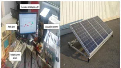
5. 1. Hardware Details Four panels mono-crystalline solar PV modules (BP580) of specifications mentioned in Table 2, with boost converter have been used for experimental analysis of proposed and existing MPPT techniques.
real time based on DS1104 of dSPACE. This control platform provides libraries to establish communication with the MATLABTM/Simulink environment. dSPACE libraries allow you to include I/O blocks that communicate with SIMULINK diagrams so that the input blocks allow you to obtain signals from the actual system being controlled and the output blocks allow you to send signals to the system been controled.
SIMULINK diagrams can be converted to C code using the Real-Time Workshop (RTW) Toolbox. This code C is compiled and an executable is sent to the Digital Signal Processor (DSP) integrated in the DS1104 card which is in charge of executing the real- time control algorithm. The software provided by dSPACE includes a graphical interface called Control Desk that allows monitoring and control in real time and shows the evaluation of the new modeling of FLC MPPT. This software also allows to save the results of the experimental tests that are done in files of data that later can be processed and represented graphically in the MATLABTM environment.
Figure 5 shows the block diagram of the hardware configuration where you can see the PV panels, the DC-DC converter, the DS1104 control platform and the resistive load connected to the system. The capacitor C provides a greater stability of the static operating point of the PV generator.
Figure 6 shows the SIMULINK block diagram of the proposed control scheme that has been implemented on the DS1104 real-time control board. Figure 7 shows the photograph of the laboratory setup. The solver is ode1 (Euler), the step size is 10-4 and the hardware clock frequency : CPU clock: 250 MHz.
TABLE 1. Fuzzy rules
ΔI
ΔV NB NM ZE PM PB
NB ZE PM PM PB PB
NM NS ZE PM PM PB
ZE NS NS ZE PM PM
PM NB NS NS ZE PM
PB NB NB NM NM ZE
TABLE 2. PV module parameters at standard test conditions
Short circuit current Isc 4.7 A
Open circuit voltage Voc 22 V
Current at maximum power point IMPP 4.44 A
Voltage at maximum power point VMPP 18V
Number of cells in series Ns 36
Pmax 80W
As can be seen in this diagram, the measured voltage and current obtained directly from generator. Figure 6 shows the SIMULINK block diagram of the proposed control scheme that has been implemented on the DS1104 real-time control board. Figure 8 shows the photograph of the laboratory setup. The solver is ode1 (Euler), the step size is 10-4 and the hardware clock frequency: CPU clock: 250 MHz. As can be seen in this diagram, the measured voltage and current obtained directly from generator PV through the channels C5 and C6, where the model of FLC MPP is developed to generate the control output, which will be the appropriate duty cycle D so that the DC-DC converter provides a suitable value of the load resistance of the PV that the PV works in the MPP.
Figure 5. Simulink model of triangular membership function
Figure 6. Fuzzy logic MPPT in MATLABTM/Simulink
environment and its implementation in dSPACE 1104
As can be seen in the diagram, the output of the MPPT FLC is sent to the block DS1104SL DSP PWM, which is responsible for generating of a PWM signal with the duty cycle sent to it by the MPPT FLC.
6. RESULTS AND DISCUSSION
Response of MPPT fuzzy logic algorithm vis-a-vis load variation:
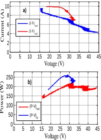
Figures 8 and 9 represent the I-V and P-V characteristics and show the impact of the load variation
R1,2,3,4=[9.8, 7.6, 4.6, 2] Ω. Under this condition, our
algorithm converges to different operation points of the PV system for each value variation of the load. The modelisation of the MPPT FLC allows us to obtain some new results, where the classical FLC controller MATLABTM/Simulink block could not provide us this information.
0 5 10 15 20 25 30 35 40 45
0 2 4 6 8 10
Votage (V)
C u r r e n t ( A ) (I-V)out (I-V)out a)0 5 10 15 20 25 30 35 40 45
0 50 100 150 200 250
Voltage (V)
P o w e r ( W) (P-V) out (P-V) in b)Figure 8. FLC-MPPT according load variation: a) I-V and b) P-V. The ripple frequency is 270Hz
Figure 9. Output of membership function of the input current ΔIpv modeled in Simulink
Figures 9 and 10 present the outputs of five membership functions of the current ΔIpv and voltage ΔVpv inputs, and the output ΔD variation when we applied different load variations.
Figure 11 and 12 represent respectively the variation of power, voltage and current of the PVsystem under load variation.
Both the outputs of the PV panel and the boost converter are represented in these figures.
0 2 4 6 8
0 0.3 0.6 0.91
Membership Functions of the 2nd Input Variable (DVpv)
M e m b e r s h i p G r a d e s Nb Nm ZZ Pb Pm a)
0 2 4 6 8
0 0.3 0.6 0.91
Membership Functions of the output Variable (D)
M e m b e r s h i p G r a d e s Pb Pm Nm Nb ZZ b)
(a) (b)
Figure 10. Outputs of memberships function of the inputs voltage ΔVpv and duty cycle ΔD modeled in Simulink
0 2 4 6 8
0 50 100 150 200 250
Time (s)
P o w e r ( W) Pout Pin a)0 2 4 6 8
0 2 4 6 8 10
Time (s)
C u r r e n t ( A ) Iout Iin b)(a) (b)
Figure 11. Responses of the power and the current for a load variation
0 2 4 6 8
0 0.3 0.6 0.91
Membership Functions of the 1st Input Variable (DIpv)
This variation will involve a fast change of the optimal panel voltage, and the MPPT algorithm reacts in a fast and consistent behavior. Equipped with a boost converter and with load change, the system tries to find the maximum power for each variation. The MPPT FLC algorithm gives the appropriate duty cycle D applied to the PWM to make pulse of the boost switch, so that the actual power is increased to operate in MPP Figure 12. Figure 13 represents the fast Fourier transform analysis of the output voltage under load variation. The ripple frequency is 270Hz.
0 2 4 6 8
0 10 20 30 40
Time (s)
V
o
lt
a
g
e
(
V
)
V
out
V
in a)
0 2 4 6 8
0 0.1 0.2 0.3 0.4 0.5 0.6
Time (s)
D
u
ty
c
y
c
le b)
Figure 12. Responses of the voltage and the duty cycle for a load variation
Figure 13. Fast Fourier transform analysis of the output voltage
6. CONCLUSION
The study presented in this paper focuses on both the modeling and implementation system using MPPT FLC algorithms to maximize the output PV system voltage, and enabling the boost converter to operate at maximum power point.
The modelisation of the MPPT FLC gives us the opportunity to extract more information and results than the conventional MATLABTM/Simulink fuzzy controller block in MATLABTM/Simulink and also simplifies the study and implementation of the this kind of algorithm. It guarantees the tracking speed, but also improve the tracking accuracy. The proposed control system is developed in the MATLABTM/Simulink environment and real-time implementation was performed using the DS1104 card dSPACE.
7. REFERENCES
1. Bose, B.K., "Global warming: Energy, environmental pollution, and the impact of power electronics", IEEE Industrial
Electronics Magazine, Vol. 4, No. 1, (2010), 6-17.
2. Masoum, M. and Dehbonei, H., "Design, construction and testing of a voltage-based maximum power point tracker (vmppt) for small satellite power supply", (1999).
3. Underland, R. and Robinson, W.P., Power electronics converters, applications and design. 2001, John Wiley & Sons, New Delhi.
4. Brunton, S.L., Rowley, C.W., Kulkarni, S.R. and Clarkson, C., "Maximum power point tracking for photovoltaic optimization using ripple-based extremum seeking control", IEEE
Transactions on Power Electronics, Vol. 25, No. 10, (2010),
2531-2540.
5. Jiang, J.-A., Huang, T.-L., Hsiao, Y.-T. and Chen, C.-H., "Maximum power tracking for photovoltaic power systems", Vol. 8, No. 2, (2005), 147-153.
6. Farhat, M., Flah, A. and Sbita, L., "Photovoltaic maximum power point tracking based on ann control", International
Review on Modelling and Simulations, Vol. 7, No. 3, (2014),
474-480.
7. Yaragatti, U.R., Rajkiran, A.N. and Shreesha, B.C., "A novel method of fuzzy controlled maximum power point tracking in photovoltaic systems", in Industrial Technology, 2005. ICIT 2005. IEEE International Conference on, IEEE., (2005), 1421-1426.
8. Patcharaprakiti, N., Premrudeepreechacharn, S. and Sriuthaisiriwong, Y., "Maximum power point tracking using adaptive fuzzy logic control for grid-connected photovoltaic system", Renewable Energy, Vol. 30, No. 11, (2005), 1771-1788.
9. Cheikh, M.A., Larbes, C., Kebir, G.T. and Zerguerras, A., "Maximum power point tracking using a fuzzy logic control scheme", Revue des energies Renouvelables, Vol. 10, No. 3, (2007), 387-395.
10. Ayvazyan, G., Kirakosyan, G. and Vardanyan, A., "Maximum power operation of pv system using fuzzy logic control",
Armenian Journal of Physics, Vol. 1, No. 2, (2008), 155-159.
11. El Hajjaji, A., BenAmmar, M., Bosche, J., Chaabene, M. and Rabhi, A., Integral fuzzy control for photovoltaic power
0 1 2 3 4 5 6 7 8
0 20 40
Time (s)
O
u
t
p
u
t
v
o
lt
a
g
e
(
V
)
0 50 100 150 200 250 300 350 400 450 500
0 0.5 1 1.5
Frequency (Hz) DC = 38.71 , THD= 2.14%
M
a
g
(
%
o
f
D
C
systems, in Sustainability in energy and buildings. 2009, Springer.219-228.
12. Di Dio, V., La Cascia, D., Miceli, R. and Rando, C., "A mathematical model to determine the electrical energy production in photovoltaic fields under mismatch effect", in Clean Electrical Power, 2009 International Conference on, IEEE., (2009), 46-51.
13. Saadi, A. and Moussi, A., "Optimisation of buck-boost converter by mppt technique with a variable reference voltage applied to photovoltaic water pumping system under variable weather condition", Asian Journal of Information Technology, Vol. 6, No. 2, (2007), 222-229.
14. Villalva, M.G., Gazoli, J.R. and Ruppert Filho, E., "Comprehensive approach to modeling and simulation of photovoltaic arrays", IEEE transactions on power electronics, Vol. 24, No. 5, (2009), 1198-1208.
15. Drid, S., Chrifi-Alaoui, L., Bussy, P. and Ouriagli, M., "Robust control of the photovoltaic system with improved maximum
power point tracking", in Ecological Vehicles and Renewable Energies (EVER), 2014 Ninth International Conference on, IEEE., (2014), 1-7.
16. Dhassa, A., Natarajana, E. and Lakshmi, P., "An investigation of temperature effects on solar photovoltaic cells and modules",
International Journal of Engineering-Transactions B:
Applications, Vol. 27, No. 11, (2014), 1713.
17. Tarek, B., Said, D. and Benbouzid, M., "Maximum power point tracking control for photovoltaic system using adaptive neuro-fuzzy “anfis”", in Ecological Vehicles and Renewable Energies (EVER), 2013 8th International Conference and Exhibition on, IEEE., (2013), 1-7.
18. Rad, M.J. and Taheri, A., "Digital controller designbased on time domain for dc-dc buck converter", International Journal
of Engineering-Transactions B: Applications, Vol. 28, No. 5,
(2015), 693.
A New Implementation of Maximum Power Point Tracking Based on Fuzzy Logic
Algorithm for Solar Photovoltaic
System
T. Boutabbaa,b, S. Drida, L. Chrifi-Alaouic, M. E. Benbouzidd
a University of Batna2, Moustaphe Benboulaid, Laboratoire LSPIE, Anevue Med Elhadi Boukhlouf, 05000, Algeria b University of Khenchela, BP 1252 Route de Batna Khenchela, 40004, Algeria
c University of Picardie Jules Verne, LTI (EA,3899), 13 av F. Mitterrand, 02880 Cuffies, France d University of Brest, EA 4325 LBMS Rue de Kergoat- CS 93837, 29238 Brest, France
P A P E R I N F O
Paper history: Received 20 June 2017
Received in revised form 03 January 2017 Accepted 04 January 2018
Keywords: Photovoltaic DC-DC Converter Boost
Modelisation Fuzzy Logic
هديكچ
( ازجم کییاتلووتف کی یارب دیدج لرتنک یاهحرط یارجا و یزاس لدم ،هلاقم نیا رد
PV
تسا اب ) زا هداف قطنم هدننک لرتنک
( یزاف
FLC
هئارا ) هدش متسیس .تسا
PV
هدننک تیوقت لدبم کی طسوت
DC-DC
لصتم راب کی هب یم
لرتنک .دوش
هدننک
FLC
( بسانم راک هخرچ
D
لدبم یارب ار )
DC-DC
متسیس یارب
PV
یم مهارف دح ات دنک .دنک دیلوت ار ورین رثکا
هدننک لرتنک هدننک دودسم زا هدافتسا
FLC
طیحم رد
Simulink
/
TM
MATLAB
یم ناسآ ار نآ یارجا .دنک
ب نیا ا
یاه هدننک دودسم یاهرتماراپ مامت دوجو
FLC
ت یمن ،راب ره نآ ددجم یحارط نودبو دنتسین سرتسد رد حلاصا دنناو
دوشیم ام متسیس لرتنک یارب یهجوت لباق نامز نتفر تسد زا بجوم هک دنوش
.
اقن نیا زا یریگولج یارب هداس و صی
لدم اه هدننک دودسم مامت حرط و یسرتسد یزاس تیوضع عباوت یزاس
FLC
.تسا هدش لیدبت ترورض کی هب ش
هیب
متسیس کی رب یبرجت یاه شیامزآو یزاس
PV
یم ناشن هک دهد
FLC
( تردق رثکادح هطقن زا یبوخ یبایدر
MPPT
)
یم مهارف ار درکلمع ام تیاهن رد .دنک
FLC
ییاتلووتف لنپ کی زا لکشتم یعقاو متسیس کی یور رب ار ( لدم ک
BP580
)
زرا هدرک یبای لاتیجید لانگیس هدنزادرپ کی یور رب ار لرتنک یژتارتسا و میا
dSPACE DS1104
ک ارجا هدر .میا
doi: 10.5829/ije.2018.31.04a.09