MATERIALS AND MICROSTRUCTURES FOR HIGH
TEMPERATURE ELECTROCHEMICAL DEVICES THROUGH
CONTROL OF PEROVSKITE DEFECT CHEMISTRY
Dragos Neagu
A Thesis Submitted for the Degree of PhD
at the
University of St Andrews
2013
Full metadata for this item is available in
St Andrews Research Repository
at:
http://research-repository.st-andrews.ac.uk/
Please use this identifier to cite or link to this item:
http://hdl.handle.net/10023/3606
1
Materials and Microstructures for High
Temperature Electrochemical Devices through
Control of Perovskite Defect Chemistry
Dragos Neagu
Supervised by Professor John T. S. Irvine
A Thesis Submitted for the Degree of PhD
at the
University of St Andrews
3
D
ECLARATION
I, Dragos Neagu, hereby certify that this thesis, which is approximately 60,000 words in length, has been written by me, that it is the record of work carried out by me and that it has not been submitted in any previous application for a higher degree.
I was admitted as a research student in November, 2008 and as a candidate for the degree of PhD in September, 2009; the higher study for which this is a record was carried out in the University of St Andrews between 2008 and 2012.
Date ………. signature of candidate ……..………
I hereby certify that the candidate has fulfilled the conditions of the Resolution and Regulations appropriate for the degree of PhD in the University of St Andrews and that the candidate is qualified to submit this thesis in application for that degree.
Date ……… signature of supervisor ………
In submitting this thesis to the University of St Andrews I understand that I am giving permission for it to be made available for use in accordance with the regulations of the University Library for the time being in force, subject to any copyright vested in the work not being affected thereby. I also understand that the title and the abstract will be published, and that a copy of the work may be made and supplied to any bona fide library or research worker, that my thesis will be electronically accessible for personal or research use unless exempt by award of an embargo as requested below, and that the library has the right to migrate my thesis into new electronic forms as required to ensure continued access to the thesis. I have obtained any third-party copyright permissions that may be required in order to allow such access and migration, or have requested the appropriate embargo below.
The following is an agreed request by candidate and supervisor regarding the electronic publication of this thesis:
Access to printed copy but embargo of electronic publication of thesis for a period of one year on the following grounds:
Publication would preclude future publication.
4
A
CKNOWLEDGMENTS
I would like to express my sincere gratitude to my supervisor, Professor John T. S. Irvine, for offering me the opportunity to join his research group and thus make contact with people from a diverse area of expertise and culture. I am especially grateful to him for allowing me to explore different aspects of solid state chemistry independently while also providing key guidance at the right time.
I would also like to thank my friend and colleague Dr. George Tsekouras for a constructive, dynamic, inspiring and enjoyable collaboration which contributed significantly to this thesis.
5
I am also much obliged to various people in the School of Chemistry for their help with experimental matters and valuable recommendations, including Mrs. Silvia Williamson (TGA, dilatometry), Mr. Ross Blackley (SEM, XRD), Mr. George Anthony, Mr. Robert Cathcart and Mr. Brian Walker for fixing various pieces of equipment.
I am very grateful to Dr. Hervé Ménard (Sasol, St Andrews) for XPS measurements and for many other recommendations and discussions but also to Sasol Technology (UK) in St. Andrews for providing access to the XPS facility.
I would also like to give my heartfelt thanks to my high school chemistry teacher, Mrs. Diana Antonia Petcu, for helping me to discover myself; I will forever be in your debt.
6
A
BSTRACT
The development of technologies that enable efficient and reliable energy inter-conversion and storage is of key importance for tempering the intermittent availability of renewable energy sources, and thus for developing an energy economy based on sustainable, clean energy production. Solid oxide electrolysis cells (SOECs) may be used to store excess electrical energy as hydrogen, while solid oxide fuel cells (SOFCs) could convert back hydrogen into electricity, thus balancing energy availability and demand. However, the current state-of-the-art hydrogen electrode used in both SOECs and SOFCs, the Ni-yttria-stabilised zirconia cermet (Ni-YSZ), is unreliable in conjunction with intermittent energy sources, in particular due to its innate redox instability.
This thesis explores the fundamental properties of various inherently redox stable A-site deficient titanate perovskite systems (A1-αBO3, B = Ti), seeking
to uncover the principles that enhance their properties so that they may be used to replace Ni-YSZ.
7
uniform size, distribution, diverse composition and ‘unconventional’ surface anchorage.
The resulting enhanced properties, and especially the exsolution phenomenon, contributed coherently towards improving the suitability of the perovskites developed here towards their application as hydrogen electrode materials. Consequently, when integrated into SOEC button cells as hydrogen electrodes, they exhibited a step-change increase in performance compared to other perovskites considered to date.
8
C
ONTENTS
Declaration ... 3
Acknowledgments ... 4
Abstract... 6
Contents ... 8
1 Introduction ... 14
1.1 The energy context ... 15
1.2 The need for energy conversion and storage ... 16
1.3 Solid oxide fuel cells – operating principle and components ... 18
1.4 High temperature steam electrolysis ... 21
1.5 The Ni-YSZ hydrogen electrode ... 22
1.6 Alternative hydrogen electrodes ... 23
1.7 Aims of the thesis ... 30
1.8 Outline of the thesis ... 31
1.9 List of publications ... 32
References... 34
2 Background on perovskites ... 37
2.1 Classes of nonstoichiometry ... 38
2.2 Accommodation of defects in the perovskite structure ... 41
2.2.1 The ideal perovskite structure ... 41
2.2.2 Accommodation of cation substitutions ... 42
2.2.3 Accommodation of deficiency ... 46
9
2.3 Electronic structure ...52
2.4 Conduction in the perovskite lattice ...56
2.4.1 Electronic conduction ...56
2.4.2 Ionic conduction ...57
2.5 Reduction in perovskite titanates ...60
2.6 Conclusions ...62
References ...63
3 Experimental...67
3.1 Sample preparation and processing ...68
3.1.1 Solid state synthesis ...68
3.1.2 Porous pellet preparation ...70
3.1.3 Button cell manufacture for SOEC testing ...71
3.1.4 Reduction ...72
3.2 Characterisation methods and techniques...72
3.2.1 Powder X-ray diffraction ...72
3.2.2 Scanning electron microscopy ...73
3.2.3 Dilatometry ...74
3.2.4 Thermogravimetry ...74
3.2.5 DC Conductivity ...75
3.2.6 X-ray photoelectron spectroscopy ...75
3.3 SOEC testing setup ...76
References ...77
4 Crystal structure of the studied compositions ...78
4.1 Studied systems in the context of defect chemistry ...79
4.2 Methodology for solving the crystal structure from XRD...80
10
4.4 Crystal structure of La0.4+x(4-m)Sr0.4-x(4-m)Mxm+Ti1-xO3 compositions ... 93
4.5 Crystal structure of the La0.3Sr0.7MxTi1-xO3+γ compositions... 98
4.6 Crystal structure of the La0.8Ce0.1Ni0.4Ti0.6O3 composition ... 101
4.7 The variation of the unit cell size with the size and concentration of doping cations ... 102
4.8 The influence of defect chemistry on the size of perovskite cells ... 110
4.9 Summary and conclusions ... 112
References... 113
5 Reduction in perovskites ... 114
5.1 Means of investigating reduction ... 115
5.2 Insights into the reduction of A-site deficient perovskites from a macroscopic perspective ... 117
5.3 Factors involved in the reduction of perovskites from an atomic scale perspective ... 125
5.4 Enhancing the extent of reduction via dopants that promote oxide ion mobility ... 129
5.5 The meaning of doping levels in perovskites – visualising doping in the crystal lattice ... 134
5.6 The importance of defect ordering in reduction ... 139
5.7 The importance of bond strength in reduction ... 141
5.8 The importance of the coordination number in reduction ... 144
5.9 The importance of perovskite defect chemistry in reduction ... 153
5.10 The extent of reduction as a measure of perovskite redox stability 157 5.11 Reduction in the special case of Ga-doped, A-site deficient perovskites ... 158
11
5.11.2 Quantification of Ga loss and extent of reduction ... 160
5.11.3 Ga loss: possible reasons and proposed mechanisms ... 164
5.11.4 TEM perspective of Ga loss ... 168
5.11.5 Designing Ga-containing perovskites that do not lose Ga on reduction 170 References ... 173
6 Enhancing electronic conductivity in strontium titanates ... 175
6.1 The strategy ... 176
6.2 Factors that determine the conductivity of perovskite titanates .... 177
6.3 Conductivity characteristics of the undoped, A-site deficient titanate La0.4Sr0.4TiO3 ... 180
6.3.1 The effect of synthesis conditions (air vs. 5%H2/Ar) on conductivity ... 180
6.3.2 The σ – T and μ – T dependencies ... 182
6.3.3 The σ – δ dependency ... 184
6.3.4 The conductivity dependence upon reduction temperature and sample porosity ... 189
6.3.5 The effect of pO2 variation on conductivity (redox cycling) ... 191
6.4 Conductivity in the Ga-doped series La0.4Sr0.4GaxTi1-xO3-γ ... 193
6.4.1 The σ – δ dependency ... 193
6.4.2 The effect of pO2 variation on conductivity and the ‘core-shell’ effect 194 6.5 Conductivity in the transition metal doped series La0.4Sr0.4MxTi1-xO3-γ (M = Fe, Ni, Zn, x = 0.06) ... 197
6.5.1 The σ – δ dependency ... 197
6.5.2 The μ – T dependency ... 199
12
7 Perovskites decorated with in-situ exsolved nanoparticles through control of defect chemistry ... 202
7.1 B-site exsolution from A-site deficient titanates ... 203 7.2 In-situ exsolution – literature context ... 206 7.3 The microstructure of the perovskites used in exsolution studies . 210
7.4 Defect chemistry-driven exsolutions ... 211 7.5 Perovskite surface structuring and the exsolution phenomenon ... 217 7.5.1 Perovskite surface morphology ... 217 7.5.2 Possible termination layers for SrTiO3 surfaces ... 219
7.5.3 Exsolutions from native vs. ‘randomly’ terminated perovskite surfaces ... 223 7.5.4 Exsolutions from perovskites with different degrees of A-site occupancy ... 229 7.5.5 The stability of the exsolved nanoparticles on ageing ... 231 7.5.6 The stoichiometry of A-site deficient perovskite surfaces ... 233 7.6 Demonstration of simultaneous in-situ exsolution of metallic and oxide nanoparticles ... 236
7.6.1 Stoichiometry design considerations for La0.8Ce0.1Ni0.4Ti0.6O3 236
7.6.2 The nature of the exsolutions in La0.8Ce0.1Ni0.4Ti0.6O3 ... 237
7.7 Overview of the exsolution mechanism ... 241
7.8 Summary, applications and implications of the exsolution phenomenon ... 243 References... 246 8 High temperature steam electrolysis with transition metal doped, A-site deficient titanate cathodes ... 248
13
8.3 The performance of selected A-site deficient titanates as HTSE cathodes ... 250 8.4 HTSE titanate-based cathode performance and defect chemistry . 252 8.5 Conclusions and outlook ... 254 References ... 255
14
15
1.1
The energy context
Throughout history, the number and sophistication of energy sources but also the amount of energy used by the human race has gradually increased, closely reflecting the stage of its development. Currently, the global energy economy is dominated by fossil fuels (see Figure 1-1), but this is expected to shift in favour of renewable energies, in the ‘not-so-distant’ future.1–3 Among
several factors that drive the transition from fossil to renewable energy, two have proven to be particularly critical and will be highlighted next.
Figure 1-1 | World energy consumption by fuel, 1990‑2035 (1 quadrillion = 1015,
1 Btu ~ 1055 J)2.
First, it is important to realise that as the supply of crude oil will peak soon, there will be not enough (cheap) oil to sustain world-wide economic growth.1,2 Secondly, the burnout of fossil fuels is always accompanied by
emission of greenhouse gases such as CO2 which have been demonstrated to
[image:16.595.183.444.275.482.2]16
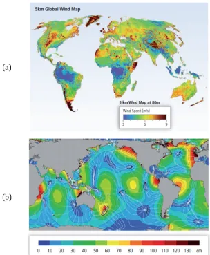
In this context, there have been considerable world-wide efforts towards building an energy economy that is largely based on renewable energy generation from e.g. wind, tidal, wave, hydroelectric, biomass and photovoltaic systems, and that is less reliant on fossil fuels. The United Kingdom and Scotland in particular benefit from a considerable supply of renewable energy in the form of wind and tidal energy (Figure 1-2).
(a)
[image:17.595.123.428.219.589.2](b)
Figure 1-2 | Global distribution of energy resources: (a) wind power and (b) tidal power.5
1.2
The need for energy conversion and storage
17
vary considerably both over time and in intensity while also being highly unpredictable.
In this context, the ability to interconvert and store energy will be critical for running an economy reliant on renewables.1,3,5 A very attractive technology
that would enable this and bring other benefits is presented in Figure 1-3.
Figure 1-3 | Excess renewable energy could be stored as H2 which in turn could be used
when the need arises.
Thus, whenever possible, renewable energy would be used directly into the power grid (Figure 1-4), while power that is collected but cannot be accommodated at a certain time by the grid (excess power) could be directed towards an electrolysis cell. The role of the electrolysis cell is to use the excess power to convert water into H2 and O2. In this scenario, H2 is the energy
carrier and it will be stored for future use. Oxygen is also a valuable product, particularly useful in hospitals. When the direct renewable energy output cannot cope with the demand in the grid, part of the stored hydrogen may be used to balance the need, via fuel cells. Fuel cells fulfil the reverse role of electrolysis cells, converting H2 (or other available stored fuels) and O2 (from
air) into electrical power and water, with reduced CO2 emissions.
Power control
and distribution Electrolysis cell
Fuel cell
H2Store
Excess power
18
Figure 1-4 | Wind energy, electricity demand and instantaneous penetration levels in West
Denmark for a week in January 2005.5
1.3
Solid oxide fuel cells – operating principle and
components
As briefly explained above, fuel cells are devices that convert the chemical energy of a fuel into electrical energy through a series of electrochemical reactions between the fuel and oxygen.6,7 The fuel and the oxidant never
come into direct contact with each other in the process and thus combustion and the subsequent Carnot limitations are entirely avoided. Hence, fuel cells can potentially deliver higher fuel efficiency conversion compared to traditional energy conversion devices such as combustion engines.6,8 Among
other types of fuel cells Solid Oxide Fuel Cell (SOFCs) are particularly attractive because they operate at high temperatures which means they can potentially run on a wider variety of fuels and also produce exhaust heat which can be used in combined heat and power systems.7
A schematic representation of a SOFC is given in Figure 1-5. In a simplified view, a SOFC consists of two porous electrodes (hydrogen electrode and
cathode) separated by a dense electrolyte. At the cathode side, molecular O2 is
reduced to oxygen anions O2-, using electrons from the external circuit:
1
19
Thus, the cathode must possess high electrocatalytic activity towards O2
dissociation but also sufficient electronic conductivity to accomplish this task.9,10 Additionally, as for the other two main SOFC components, it is
important that the material of choice is chemically and dimensionally stable in operating conditions while having similar thermal expansion coefficient to the other cell components.6,11 The most commonly used cathode material is La1−𝑥Sr𝑥MnO3 (also known as LSM), but many other mixed ionic–electronic
conductors (MIECs) such as La0.6Sr0.4Fe0.8Co0.2O3 (LSFC), 12
Ba0.5Sr0.5Co0.8Fe0.2O3−δ (BSCF),13 are known to perform extremely well as
SOFC cathodes.10,14
Solid Oxide Fuel Cell(SOFC) Solid Oxide Electrolysis Cell (SOEC)
Figure 1-5 | Solid Oxide Fuel Cell (Left) and Solid Oxide Electrolysis Cell (Right) - schematic illustration of components and operating principle.
The electrolyte is made dense in order to avoid the direct reaction between the fuel and oxidant and chosen such that it displays very good oxide ion conductivity but no electronic conductivity, in order to force the electrons to travel exclusively through the outer circuit. Apart from the above mentioned requirements, the electrolyte must withstand the considerable 𝑝O2 gradient
between the cathode (𝑝O2~ 1 atm) and the hydrogen electrode
(𝑝O2~ 10−20 atm) which in fact constitutes the driving force for oxide ion
20
(YSZ). Some other oxides, such as doped ceria, La0.9Sr0.1Ga0.8Mg0.2O2.85
(LSGM), are also under consideration because they have higher ionic conductivities.11,15,16
After travelling through the electrolyte, the oxide ions will reach the hydrogen electrode and react with the fuel to release the oxidation product (e.g. water) and electrons:
H2+ O2−→H2O + 2e− Eq. 1-2
Therefore, it is important that the hydrogen electrode exhibits good catalytic properties towards fuel oxidation but also good electronic conductivity in order to enable fast electron transfer to the conducting contacts (e.g.
interconnects). Usually electronic conductivity of at least 100 S⋅cm−1is
required but it has been shown that through appropriate cell design, materials with conductivity values as low as 1 S⋅cm−1 can be used
succesfully.17 The hydrogen electrode must also be stable in highly reducing
conditions and be compatible with the adjacent cell components (the electrolyte and the interconnect) while still being sufficiently porous to allow the gas species access to the sites where the electrochemical oxidation occurs.7 Ideally, the hydrogen electrode should also be electrochemically
active and tolerant with respect to various fuels, especially if they contain a small measure of impurities (e.g. sulphur).
The most commonly used SOFC hydrogen electrode is a composite consisting of Ni metal and the oxide ion conducting ceramic YSZ (hence the name ‘cermet’).18 A more detailed view of the performance and limitations of this
21
1.4
High temperature steam electrolysis
As mentioned in section 1.2 in passing, electrolysis cells are electrochemical devices that can split water into H2 and O2 by using electricity and are
environmentally clean as long as the electricity comes from a renewable source. High Temperature Steam Electrolysis (HTSE) is a highly efficient electrolysis process that is carried out in Solid Oxide Electrolysis Cells (SOECs) and uses not only electrical energy but also thermal energy.19,20 The
advantage of performing steam electrolysis at high temperature comes from the fact that as the temperature increases, the electrical energy demand (ΔG) decreases, while the thermal energy demand (T∙ ΔS) increases and the total heat demand (ΔH) increases slightly. This means that less electrical energy may be required for the electrolysis of steam as the temperature increases. Additionally, as in the case of SOFCs, operation at high temperatures results in faster electrode kinetics.21
Figure 1-6 | Electrical, heat and total energy requirements for water electrolysis as a function
of temperature.19
A related process is combined electrolysis of steam and carbon dioxide leading to synthesis gas from which several valuable compounds such as methanol or dimethyl ether may be produced.1
22
consumed to generate fuel. Both the SOEC and the SOFC consist in principle of the same three components: an electrolyte, an hydrogen electrode and a cathode. The denomination of the latter two is, however, interchanged to reflect appropriately the redox processes that occur in each case. Thus, the hydrogen electrode of the fuel cell comes in contact with the same species as the cathode of the electrolysis cell, H2, H2O, e−, hence this side of a SOFC or
SOEC is often referred to as the hydrogen electrode. Moreover, since the same species are present at the hydrogen electrode in both SOFC and SOEC, it follows that the material requirements and hence the materials themselves could be similar if not identical for both technologies. The same applies to the ‘air electrode’. Thus, it is no surprise that hydrogen electrode materials such as Ni-YSZ have been transferred to the relatively new field of high temperature electrolysis and performed equally well.18
1.5
The Ni-YSZ hydrogen electrode
Structurally, the Ni-YSZ cermet can be described as a porous assemblage of Ni and YSZ particles where each phase is in sufficient fraction to form percolating paths throughout the hydrogen electrode (Figure 1-7).22,18 The
electrochemical reactions occur preferentially across the lines where three phases (and main reactants) meet: the ceramic electrolyte (O2-), the metallic
electrode (e−) and the gas phase containing the fuel (e.g. H2).18 Hence, these
lines are known as the triple-phase boundary (TPB), and the electrochemical activity of the Ni-YSZ hydrogen electrode is directly related to the length of these boundaries. In consequence, a lot of attention has been direct towards maximising their length during preparation and minimising their degradation during operation.
The Ni-YSZ cermet excels in terms of catalytic properties for fuel oxidation (H2 and CO), steam reforming of natural gas and exhibits good current
collection, largely due to the high electrochemical activity and electronic conductivity of Ni metal.18,15 Unfortunately, the wide applicability of this
23
Figure 1-7 | Schematic representation of the Ni-YSZ hydrogen electrode microstructure and
H2 electro-oxidation occurring at the triple phase boundary (TPB).
Most importantly, it is not redox stable.23,24,18 The oxidation of Ni to NiO may
occur due to fuel starvation (e.g. lack of fuel or shut-down) or under high load (high steam conditions) and is typically accompanied by significant volume changes and Ni particle coarsening.21 These in turn leads to severe structural
degradation, considerable lowering of the TPB length and consequently sever decrease in performance. Thus, Ni-YSZ hydrogen electrodes would not be the optimal choice for use in conjunction with renewables which are inherently intermittent meaning that e.g. fast start-up/shutdown, high load/high steam are expected to be supported routinely over an adequate lifetime. Additionally, Ni-YSZ hydrogen electrodes may suffer from carbon deposition which blocks porosity21 and sulphur poisoning.25
1.6
Alternative hydrogen electrodes
Thus, having in mind the limitations exhibited by the Ni-YSZ cermet, the challenge is to develop alternative hydrogen electrodes that apart from displaying good fuel oxidation properties, electronic conductivity and reasonable stability, they must also be redox-stable, ideally single-phase, while exhibiting some degree of mixed ionic and electronic conduction. The last two characteristics are desirable in order to avoid the electrochemistry being confined to certain boundaries (e.g. the TPB), and thus to a limited fraction of the hydrogen electrode volume, like in the Ni-YSZ. Instead, in the
O
2-H
2H
2O
e
-Ni
24
case of a single phase MIEC all the surface of the hydrogen electrode that is in contact with the gas phase would theoretically be able to support electrochemical reactions since the MIEC phase could provide the flux of oxide ions and also carry away the generated electrons after the oxidation has occurred (Figure 1-8). The interface where electrochemical reactions occur would no longer be a sum of lines, but a sum of surfaces.
Figure 1-8 | Schematic comparison between: (Left) the Ni-YSZ cermet and (Right) an electro-catalytically active MIEC.
It is important to emphasize here that while high-performance, all-ceramic (single-phase), mixed ionic-electronic conductor materials have been identified for the air electrode (e.g. LSM, BSCF),14,12,13 an ideal all-ceramic
hydrogen electrode material has not yet been found.17,26 This is perhaps not
surprising, given the complexity of the functions and requirements that a hydrogen electrode material must fulfil. However, it remains an open challenge driving the field forward and also constitutes one of the main
motivations of this thesis. Next, a brief, qualitative overview of the main
alternative hydrogen electrodes development directions will be presented, based on some of the reviews published on this topic recently.17,9,27,28,8,29,26,30
Stemming from the Ni-YSZ concept, some of the approaches focused on replacing the metal and the ceramic in this composite, for example with Cu and CeO2, respectively. Cu-CeO2-δ hydrogen electrodes exhibit significantly
better performance than Ni-YSZ when operated on dry hydrocarbons, including liquid fuels, without reforming,31,32 but suffers from inadequate
O
2-H
2H
2O
e
-Ni
YSZ
TPB
O
2-H
2H
2O
e
-YSZ
‘TPB’
25
redox stability and Cu agglomeration during operation (Cu has high mobility at the SOFC operating temperatures).33
Rutile-type materials (e.g. TiO2 doped with Nb, Cr etc) are redox stable,
exhibit high electronic conductivity in reducing conditions but have very limited oxide ion conductivity and fuel oxidation activity.34,35
Tungsten bronze materials (A0.6BO3) were also found to exhibit high
electronic conductivity when reduced, but their stability in reducing atmosphere, as well as catalytic activity is lacking, even when compared to other oxide hydrogen electrodes.36,37
Certain pyrochlore (A2B2O7) systems were optimised for both ionic and
electronic conductivity through doping, giving hope of MIEC behaviour. While electrochemical performance was reasonable with adequate B-site dopants, the stability of the phases even in reducing atmosphere still constitutes an issue.38,39
Some of the most exciting results have been obtained, however, for compositions belonging to the perovskite crystal structure (ABO3). This is
most likely a result of the unique properties and convenient engineering opportunities offered by the perovskite structure environment. This, along with in-depth look at the structure and properties of perovskites will be discussed in more detail in Chapter 2. Some key aspects are worth mentioning here in passing, however.
26
Also, the vast majority of known catalytically active cations such as transition metal cations can substitute on the B-site the perovskite structure. This provides a lot of flexibility for tailoring catalytic activity and specific functionality in general. Moreover, some of these transition metal cations also support multiple oxidation states under different conditions which in turn may give rise to (high) electronic conductivity. Additionally, the presence of cations with variable oxidation states enables the creation (i.e.
doping) of oxygen vacancies in reducing environment (e.g. operating
conditions):
2BBx+ OOx ⇌2BB′ + VO∙∙+12O2 Eq. 1-3
This potentially gives rise to more adsorption sites45 and hopping sites for
oxide ion conduction, and thus to mixed electronic and ionic conductivity.26
Most of the perovskite hydrogen electrode materials developed so far stemmed from two perovskites: LaCrO3 (chromites) and SrTiO3 (titanates)
mainly because these show exceptional stability in both oxidising and reducing conditions at high temperatures, providing a robust structure for further tailoring.27
On the basis of this stability and because LaCrO3 and some of its derived
compositions show exclusively electronic conduction, they have been successfully employed as interconnects.8 Chromites however possess low
inherent catalytic activity and lack oxide ion conduction possibly as a result of the strong preference Cr3+ has for 6-fold coordination, the full coordination
of the B-site in perovskites.27,46 This can be remedied to some extent by
replacing some of the Cr with other transition metals that form cations which do support flexible coordination (e.g. Mn, Co, Fe).47–50 Among
chromites, the most impressive performance is demonstrated by the double
perovskite (A2BB’O3) La0.75Sr0.25Cr0.5Mn0.5O3−γ (LSCM) which has been
designed especially for improved B-site coordination flexibility.46 As such,
27
material is redox stable52,46 and exhibits comparable electrochemical
performance to Ni/YSZ cermets at 900 °C in 97%H2/3% H2O, but also
displays good performance for methane oxidation without using excess steam.46 Perhaps the major limitation of LSCM is the fact that it is a p-type
conductor.53 P-type conduction occurs through electron holes and most
importantly increases with the increase of 𝑝O2:
VO∙∙+12O2⇌OOx + 2ℎ∙ Eq. 1-4
This means that the conductivity of LSCM will be maximised in oxidising conditions, not in the reducing conditions found at the hydrogen side. For example, the conductivity of LSCM at 900 °C in air is ~ 30 S⋅cm-1, and in
10%H2/N2 decreases to just below 1 S⋅cm-1.54 Thus, ideally, hydrogen
electrode materials should exhibit n-type conduction. In this case the charge carriers are electrons and the conductivity increase with the decrease of 𝑝O2:
OOx ⇌VO∙∙+12O2+ 2𝑒′ Eq. 1-5
Thus, the stronger the reducing conditions become at the hydrogen electrode, the higher the number of charge carriers generated, resulting in increased electronic conductivity and current collection.
From this point of view, titanates appear to be a more natural choice for the hydrogen electrode compared to chromites, since titanates are primarily n-type conductors. Indeed, in reducing conditions a fraction of the Ti4+ ions
reduce to Ti3+ according to the equilibrium described by Eq. 1-3. Additionally,
Ti4+ is known to adopt 5-fold coordination to some degree which would allow
for chemisorption, while the Ti4+/Ti3+ redox couple is generally capable of
accepting electrons from a hydrocarbon or from H2, potentially carrying out
the chemisorption dissociation reaction of these fuels.29 Even so, SrTiO3 is a
poor n-type conductor with little catalytic activity of its own.30,55
28
will be shown in Chapter 2, titanates (but other perovskites as well, e.g.
chromites) can be doped in various ways to give rise to different defects and corresponding nonstoichiometry classes. The sum of characteristics (e.g.
composition, structure, properties, behaviour) that a certain type or combination of defects bestows upon the perovskite that is part of is usually referred to as the defect chemistry of that perovskite nonstoichiometry class. When carefully tailored, defect chemistry can give rise to unique and potentially useful properties. Among the most important perovskite nonstoichiometry classes, A-site stoichiometric, oxygen deficient perovskites (ABO3−γ) were exemplified for chromites (e.g. LSCM) while A-site
stoichiometric, oxygen excess (ABO3+γ) and A-site deficient perovskites
(A1−αBO3) will be discussed for titanates.
Excess is generally incorporated by alternating perovskite slabs with
intergrowth regions where the excess species are located.56–58 In the case
where only oxygen excess is present, such as in La𝑥Sr1−𝑥TiO3+𝑥 2⁄ ,
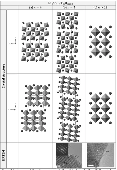
(equivalently, La4Sr𝑛−4Ti𝑛O3𝑛+2), the intergrowth comprises of the region
where perovskite slabs are offset in such a way to allow accommodation of extra oxygen ions (see Chapter 2). At high oxygen excess values the intergrowths are ordered in oxygen rich planes and constitute crystallographic features. As the amount of excess oxygen decreases, the ordering is gradually broken to the point corresponding to
γ=𝑥⁄2 = 2⁄𝑛 < 0.167 (𝑥 ≤1 3⁄ , or 𝑛 ≥12), below which oxygen-rich defects are randomly distributed within the perovskite framework.57,59 The
presence of extra oxygen beyond the ABO3 stoichiometry not only causes
changes in the perovskite structure, but has implications on the electrochemical properties as well. As the ordering is broken below γ < 0.167, presence of such disordered defects appears to strongly the affect the titanate which becomes easier to reduce, achieves higher electronic conductivity and exhibits much better performance in high temperature steam electrolysis than its oxygen stoichiometric analogues.59,20 In spite of
29
materials does not improve considerably, perhaps due to the strong preference of Ti4+ for 6-fold coordination.42,60 Once Mn and Ga are doped on
the B-site, La4Sr8Ti11𝐺𝑎0.5𝑀𝑛0.5O38−γ, the performance of this material
increase dramatically in a SOFC running on wet hydrogen and is active for methane oxidation as well.59 The oxygen excess series La𝑥Sr1−𝑥TiO3+𝑥 2⁄ has
received a lot of attention, with numerous other dopants tested to achieve further property improvements over La4Sr8Ti11𝐺𝑎0.5𝑀𝑛0.5O38−γ, without
much success however.61–63
In A-site deficient titanates some of the A-sites are simply vacant. The most representative A-site deficient series are obtained by doping La3+ or Y3+ in
SrTiO3, leading to La𝑥Sr1−3𝑥 2⁄ TiO364 and Y𝑥Sr1−3𝑥 2⁄ TiO3,65 respectively (see
Chapter 2). A-site deficiency offers a number of advantages over oxygen excess stoichiometry. A-site vacancies provide hopping sites for A-site cations which during phase formation or processing enhances grain growth and sintering allowing the production of mechanically robust microstructures at lower temperatures.66,67 Also, La- or Y-containing
perovskites may suffer degradation over time in high steam environment on account of the ‘lanthanum oxide’ in the perovskite reacting with the steam to form hydroxides La(OH)3, a process accompanied by a significant change in
volume. A slight number of A-site vacancies has been found to mitigate this.66
Additionally, the electronic conductivity of A-site deficient titanates (e.g. La𝑥Sr1−3𝑥 2⁄ TiO3, 𝑥< 0.4) tends to be slightly higher compared to oxygen
excess titanates (e.g.La𝑥Sr1−𝑥TiO3+𝑥 2⁄ , 𝑥< 1/3).20,63 This is probably due to
the randomly distributed intergrowths that might disrupt the conduction network throughout the grain (at the intergrowths the corner sharing between octahedra is broken) leading to an overall decrease in electron mobility. In fact, recent studies on the Ruddlesden-Popper A-site excess,
oxygen excess series Sr𝑛+1Ti𝑛O3𝑛+1 have pointed out that the electron
30
On the other hand, the innate electrochemical activity of the oxygen excess perovskites (e.g.La𝑥Sr1−𝑥TiO3+𝑥 2⁄ , 𝑥= 0.3) is generally higher than their
A-site deficient analogues (e.g. La𝑥Sr1−3𝑥 2⁄ TiO3, 𝑥 = 0.2), but still better than
SrTiO3, most likely due to the functionality brought by the mobile, randomly
distributed oxygen rich defects, as explained above.20 Efforts directed
towards doping the B-site of A-site deficient titanates have not resulted, however, in the identification of a hydrogen electrode material with electrochemical performance on par with e.g. La4Sr8Ti11Ga0.5Mn0.5O38−γ. In
the case of the Y-doped A-site deficient perovskites, the influence of many B-site dopants has been studied intensively, including first row transition metals, Nb, Zr etc.65,69,70,67,71 In the case of the La-doped system, the B-site
dopants studied have been limited so far to Nb.64 Thus, additional
understanding of A-site deficient titanate systems may be obtained by exploring B-site doping in the system La𝑥Sr1−3𝑥 2⁄ TiO3.
1.7
Aims of the thesis
In the light of the context presented so far, the aim of this thesis is to explore the A-site deficient titanate systems derived from the system
La𝑥Sr1−3𝑥 2⁄ TiO3 in general and the optimised member64 𝑥= 0.4 in
particular, in order to:
Gain a wider understanding of A-site deficiency in titanates in the
context of perovskite defect chemistry, especially in the presence of other defects such as cation substitutions, oxygen vacancies etc;
Study the structure, structural characteristics and relationships in
these A-site deficient perovskites;
Identify the key parameters that control the reducibility of these
perovskites and improve it;
31
Explore ways of enhancing the electrochemical activity of these
titanates;
Demonstrate high temperature steam electrolysis using the developed
materials as hydrogen electrodes.
1.8
Outline of the thesis
The chapters of this thesis are organised as follows:
Chapter 2 (Background on perovskites) presents an overview of perovskites focusing especially on the possible nonstoichiometry classes, the way defects are accommodated in perovskites and the resulting defects chemistry in general. This chapter also includes an introduction to reduction, electronic conduction and ionic conduction in perovskites. This chapter is not an exhaustive background on perovskites, but rather reunites essential aspects and concepts related to perovskites that were deemed relevant towards analysing the results of the work presented in this thesis.
Chapter 3 (Experimental) summarises the main methods and techniques employed in this study to prepare, analyse and test the developed materials.
Chapter 4 (Crystal structure of the studied compositions) describes the main structural characteristics of the materials developed in this study. It also reveals some of the reasoning based on which entirely new compositions were derived and prepared throughout this work. Several correlations between the structure, the defect chemistry and characteristics of constituting cations are presented and discussed as well.
32
Chapter 6 (Enhancing electronic conductivity in strontium titanates) proposes and exemplifies a new approach for enhancing the electronic conductivity of A-site deficient titanates building upon the knowledge gained in the work described in Chapter 5.
Chapter 7 (Perovskites decorated with in-situ exsolved nanoparticles through
control of defect chemistry) explores a new phenomenon uncovered during
this study which enables advanced control over the growth of catalytically active nanoparticles from perovskites and which is driven primarily by defect chemistry.
Chapter 8 (High temperature steam electrolysis with transition metal doped,
A-site deficient titanate cathodes) presents an overview and brief analysis of
the performance of titanate-based cathodes developed in this study for H2
production in high temperature steam electrolysis cells.
Chapter 9 (Conclusions) summarises the main findings of this thesis.
1.9
List of publications
This thesis is based on several publications:
Published papers:
D. Neagu & J. T. S. Irvine, Structure and Properties of La0.4Sr0.4TiO3
Ceramics for Use as Anode Materials in Solid Oxide Fuel Cells. Chemistry
of Materials 22, 5042–5053 (2010).
D. Neagu & J. T. S. Irvine, Enhancing Electronic Conductivity in
Strontium Titanates through Correlated A and B-Site Doping. Chemistry
of Materials 23, 1607–1617 (2011).
G. Tsekouras, D. Neagu & J. T. S. Irvine, Step-change in high temperature steam electrolysis performance of perovskite oxide
cathodes with exsolution of B-site dopants. Energy and Environmental
33
Book chapter awaiting publication:
Neagu, D. & Irvine, J. T. S., Perovskite defect chemistry as exemplified by
strontium titanate, in Comprehensive Inorganic Chemistry II, Eds. K.R.
Poeppelmeier and J. Reedijk, Elsevier Press, In Press, 2013.
Paper under review:
D. Neagu, G. Tsekouras, D. M. Miller, H. Ménard & J. T. S. Irvine, In-situ
growth of Nanoparticles through Control of Defect Chemistry.
Papers in preparation:
G. Tsekouras, D. Neagu & J. T. S. Irvine, Redox tolerance of ceramic perovskite titanate solid oxide electrolysis cell hydrogen electrodes
G. Tsekouras, D. Neagu & J. T. S. Irvine, High temperature steam electrolysis with transition metal doped, A-site deficient titanate cathodes
34
References
1. J. T. S. Irvine, J. Power Sources, 2004, 136, 203–207.
2. International Energy Outlook 2011, U.S. Energy Information Administration,
2011.
3. A. Galich and L. Marz, Energy, Sustainability and Society, 2012, 2, 2.
4. Climate change 2007: Synthesis report., Intergovernmental Panel on Climate
Change, 2007.
5. Potsdam-Institut für Klimafolgenforschung, Renewable energy sources and climate change mitigation : special report of the Intergovernmental Panel on
Climate Change, Cambridge university press, New York, 2012.
6. N. Q. Minh and T. Takahashi, Science and Technology of Ceramic Fuel Cells, Elsevier Science, 1st edn., 1995.
7. S. C. Singhal, in Solid Oxide Fuels Cells: Facts and Figures, eds. J. T. S. Irvine and P. Connor, Springer London, 2013, pp. 1–23.
8. C. Sun and U. Stimming, J. Power Sources, 2007, 171, 247–260.
9. L. J. Gauckler, D. Beckel, B. E. Buergler, E. Jud, U. P. Muecke, M. Prestat, J. L. M. Rupp, and J. Richter, CHIMIA Int. J. Chem., 2004, 58, 837–850.
10. J. Richter, P. Holtappels, T. Graule, T. Nakamura, and L. J. Gauckler, Monatsh.
Chem., 2009, 140, 985–999.
11. D. S. C. Singhal and K. Kendall, Eds., High-temperature Solid Oxide Fuel Cells:
Fundamentals, Design and Applications, Elsevier, 2003.
12. M. Juhl, S. Primdahl, C. Manon, and M. Mogensen, J. Power Sources, 1996, 61, 173–181.
13. Z. Shao and S. M. Haile, Nature, 2004, 431, 170–173.
14. C. Sun, R. Hui, and J. Roller, J Solid State Electrochem, 2010, 14, 1125–1144. 15. T. Ishihara, Ed., Perovskite oxide for solid oxide fuel cells, Springer, New
York ;London, 2008.
16. J. B. Goodenough, Annu. Rev. Mater. Res., 2003, 33, 91–128.
17. A. Atkinson, S. Barnett, R. J. Gorte, J. T. S. Irvine, A. J. McEvoy, M. Mogensen, S. C. Singhal, and J. Vohs, Nat Mater, 2004, 3, 17–27.
18. M. Mogensen and P. Holtappels, in Solid Oxide Fuels Cells: Facts and Figures, eds. J. T. S. Irvine and P. Connor, Springer London, 2013, pp. 25–45.
19. A. Brisse, J. Schefold, C. Stoots, and J. O’Brien, in Innovations in Fuel Cell
Technologies, eds. R. Steinberger-Wilckens and W. Lehnert, RSC, Cambridge,
2010.
20. G. Tsekouras and J. T. S. Irvine, J. Mater. Chem., 2011.
21. J. T. S. Irvine and P. Connor, in Solid Oxide Fuels Cells: Facts and Figures, eds. J. T. S. Irvine and P. Connor, Springer London, 2013, pp. 163–180.
22. P. R. Shearing, J. Golbert, R. J. Chater, and N. P. Brandon, Chem. Eng. Sci., 2009, 64, 3928–3933.
23. J. Malzbender, E. Wessel, and R. W. Steinbrech, Solid State Ionics, 2005, 176, 2201–2203.
24. T. Klemensø and M. Mogensen, J. Am. Cer. Soc., 2007, 90, 3582–3588. 25. Y. Matsuzaki and I. Yasuda, Solid State Ionics, 2000, 132, 261–269.
35
27. S. Tao and J. T. S. Irvine, The Chemical Record, 2004, 4, 83–95. 28. J. W. Fergus, Solid State Ionics, 2006, 177, 1529–1541.
29. J. B. Goodenough and Y.-H. Huang, J. Power Sources, 2007, 173, 1–10.
30. X.-M. Ge, S.-H. Chan, Q.-L. Liu, and Q. Sun, Adv. Energy Mater., 2012, n/a–n/a. 31. H. Kim, S. Park, J. M. Vohs, and R. J. Gorte, J. Electrochem. Soc., 2001, 148,
A693–A695.
32. S. Park, J. M. Vohs, and R. J. Gorte, Nature, 2000, 404, 265–267.
33. N. Kiratzis, P. Holtappels, C. E. Hatchwell, M. Mogensen, and J. T. S. Irvine, Fuel
Cells, 2001, 1, 211–218.
34. C. M. Reich, A. Kaiser, and J. T. S. Irvine, Fuel Cells, 2001, 1, 249–255.
35. A. Lashtabeg, J. Canales-Vazquez, J. T. S. Irvine, and J. L. Bradley, Chem. Mater., 2009, 21, 3549–3561.
36. A. Kaiser, J. L. Bradley, P. R. Slater, and J. T. S. Irvine, Solid State Ionics, 2000, 135, 519–524.
37. P. R. Slater and J. T. S. Irvine, Solid State Ionics, 1999, 124, 61–72.
38. P. Holtappels, F. W. Poulsen, and M. Mogensen, Solid State Ionics, 2000, 135, 675–679.
39. B. J. Wuensch, K. W. Eberman, C. Heremans, E. M. Ku, P. Onnerud, E. M. E. Yeo, S. M. Haile, J. K. Stalick, and J. D. Jorgensen, Solid State Ionics, 2000, 129, 111– 133.
40. T. Ikebe, H. Muroyama, T. Matsui, and K. Eguchi, J. Electrochem. Soc., 2010, 157, B970–B974.
41. P. Blennow, K. K. Hansen, L. R. Wallenberg, and M. Mogensen, Solid State
Ionics, 2009, 180, 63–70.
42. O. A. Marina, N. L. Canfield, and J. W. Stevenson, Solid State Ionics, 2002, 149, 21–28.
43. D. M. Bastidas, S. Tao, and J. T. S. Irvine, J. Mater. Chem., 2006, 16, 1603–1605. 44. Q. Liu, X. Dong, G. Xiao, F. Zhao, and F. Chen, Adv. Mater., 2010, 22, 5478–
5482.
45. H. Dai, H. He, P. Li, L. Gao, and C.-T. Au, Catal. Today, 2004, 90, 231–244. 46. S. Tao and J. T. S. Irvine, Nature Mater., 2003, 2, 320–323.
47. S. Primdahl, J. R. Hansen, L. Grahl-Madsen, and P. H. Larsen, J. Electrochem. Soc., 2001, 148, A74–A81.
48. G. Pudmich, B. A. Boukamp, M. Gonzalez-Cuenca, W. Jungen, W. Zipprich, and F. Tietz, Solid State Ionics, 2000, 135, 433–438.
49. V. Vashook, L. Vasylechko, J. Zosel, W. Gruner, H. Ullmann, and U. Guth, J. Solid
State Chem., 2004, 177, 3784–3794.
50. V. Vashook, L. Vasylechko, J. Zosel, and U. Guth, Solid State Ionics, 2003, 159, 279–292.
51. E. S. Raj, J. A. Kilner, and J. T. S. Irvine, Solid State Ionics, 2006, 177, 1747– 1752.
52. S. Zha, P. Tsang, Z. Cheng, and M. Liu, J. Solid State Chem., 2005, 178, 1844– 1850.
53. S. M. Plint, P. A. Connor, S. Tao, and J. T. S. Irvine, Solid State Ionics, 2006, 177, 2005–2008.
36
55. P. Blennow, K. K. Hansen, L. Reine Wallenberg, and M. Mogensen, Electrochim. Acta, 2006, 52, 1651–1661.
56. M. E. Bowden, D. A. Jefferson, and I. W. M. Brown, J. Solid State Chem., 1995, 117, 88–96.
57. J. Canales-Vázquez, M. J. Smith, J. T. S. Irvine, and W. Zhou, Adv. Funct. Mater., 2005, 15, 1000–1008.
58. S. N. Ruddlesden and P. Popper, Acta Crystallogr., 1957, 10, 538–539.
59. J. C. Ruiz-Morales, J. Canales-Vázquez, C. Savaniu, D. Marrero-López, W. Zhou, and J. T. S. Irvine, Nature, 2006, 439, 568–571.
60. J. Canales-Vazquez, S. Tao, and J. T. S. Irvine, Solid State Ionics, 2003, 159, 159–165.
61. J. Canales-Vázquez, J. C. Ruiz-Morales, J. T. S. Irvine, and W. Zhou, J.
Electrochem. Soc., 2005, 152, A1458.
62. A. Ovalle, J. C. Ruiz-Morales, J. Canales-Vázquez, D. Marrero-López, and J. T. S. Irvine, Solid State Ionics, 2006, 177, 1997–2003.
63. D. N. Miller and J. T. S. Irvine, J. Power Sources, 2011, 196, 7323–7327. 64. P. R. Slater, D. P. Fagg, and J. T. S. Irvine, J. Mater. Chem., 1997, 7, 2495–2498. 65. S. Hui and A. Petric, J. Eur. Ceram. Soc., 2002, 22, 1673–1681.
66. J. W. Stevenson, T. R. Armstrong, L. R. Pederson, J. Li, C. A. Lewinsohn, and S. Baskaran, Solid State Ionics, 1998, 113-115, 571–583.
67. Q. X. Fu, S. B. Mi, E. Wessel, and F. Tietz, J. Eur. Ceram. Soc., 2008, 28, 811–820. 68. N. Sirikanda, H. Matsumoto, and T. Ishihara, Solid State Ionics, 2010, 181,
315–321.
69. S. Hui and A. Petric, J. Electrochem. Soc., 2002, 149, J1. 70. S. Hui and A. Petric, Mater. Res. Bull., 2002, 37, 1215–1231.
37
38
2.1
Classes of nonstoichiometry
Perovskite oxide materials possess general stoichiometry ABO3 in which
conventionally the A-site is occupied by the larger cation and the B-site by the smaller cation. The perovskite lattice can display nonstoichiometry virtually with respect to all three sites (A, B and O), either individually (one site at a time) or in various combinations. B-site nonstoichiometry is, however, energetically unfavourable because of the important structural role of the B-site cations,1,2 which form strong bonds with oxygen in a network
consisting of BO6 corner-sharing octahedra (see subsections 2.2.1 and 2.3)i.
Consequently, the vast majority of perovskite systems exhibit a fully occupied B-site, with few examples of B-site nonstoichiometric perovskites being known.3
With respect to a fully occupied B-site, the A-site and O-site can be sub-stoichiometric (e.g. A1−αBO3, ABO3−γ; also known as deficient) or
super-stoichiometric (e.g.A1+αBO3, ABO3+γ; usually called excess). The relationship
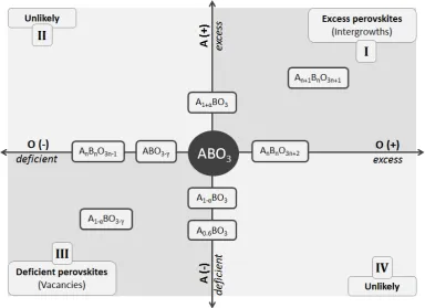
between different perovskite nonstoichiometry domains can be better understood by representing the nonstoichiometry of the A and O sublattices on Cartesian axes having the defect-free ABO3 as origin. Such a
representation is depicted in Figure 2.1. Excess perovskites including the Ruddlesden-Popper phases A𝑛+1B𝑛O3𝑛+1 (𝑛 ≥1),4,5 or the A𝑛B𝑛O3𝑛+2 (𝑛 ≥
4) homologous series,6,7 are located in quadrant I. Deficient perovskites such
as the tungsten bronzes (A0.6BO3) or the A𝑛B𝑛O3𝑛−1 series (𝑛 = 2 being the
brownmillerite structure) are located in quadrant III. Stoichiometries
exhibiting A-site excess and O-deficient (quadrant II) or A-site deficient and O-excess (quadrant IV) are unlikely to exist.
The diagram emphasizes the diametrically opposed positions of the deficient and excess variants in the perovskite nonstoichiometry landscape. While this representation provides a straightforward way to visualise different perovskite nonstoichiometry in relation to each other, it also reveals the
39
distinct defect chemistries one would anticipate from these two classes. Indeed, while deficiency can be easily accommodated by creating vacancies in the ABO3 structure (see section 2.2.3), excess stoichiometry is achieved
[image:40.595.120.505.249.528.2]through the exceptional ability of the perovskite to inter-grow with other crystal structures (see section 2.2.4). This fundamental structural difference translates into contrasting properties for these two classes, some of which will be revealed across this study.
Figure 2.1 – Perovskite nonstoichiometry represented in a Cartesian plane. 𝑥 and 𝑦 axes are
set to correspond to oxygen and A-site nonstoichiometry, respectively.
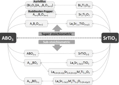
The nonstoichiometry class and hence the defect chemistry can be tailored through various approaches, including cation substitution, exposing the materials to different conditions (T, 𝑝O2), or, where possible, simply by
formulating the stoichiometry in the desired way (e.g. preparing an A-site deficient perovskite A1−αBO3 by using a mixture of raw materials having
atomic ratio A B = (1⁄ − α) 1⁄ ). Some of these approaches are exemplified below and summarised in Figure 2.2, focusing on compositions derived from the archetype perovskite, Sr2+Ti4+O
40
The perovskite structure allows for cations of similar sizeii but different
valence to be substituted on either the A-site or B-site. However, because of the different valence, various charge compensation mechanisms can be envisaged.8 Doping the A-site with a cation of higher charge than Sr2+, such as
La3+, can be compensated by introducing extra oxygen beyond the ABO3
stoichiometry (thus creating an oxygen excess perovskite) as in
La𝑥Sr1−𝑥TiO3+𝑥 2⁄ ; by creating A-site vacancies, as in La𝑥Sr1−3𝑥 2⁄ TiO3 (A-site
deficient perovskite); or by reducing the oxidation state of some Ti4+ ions, La𝑥Sr1−𝑥Ti𝑥3+Ti1−𝑥4+ O3, when Ti3+ can be stabilized, for example by preparing
[image:41.595.90.481.312.591.2]the sample in highly reducing conditions.
Figure 2.2 – Perovskite nonstoichiometry exemplified on SrTiO3.
Oxygen ion vacancies or “interstitials” (intergrowths) can be generated by substitution of Ti4+ ions with cations Mm+ of lower or higher charge
respectively, producing compounds of stoichiometry SrM𝑥Ti1−𝑥O3−(4−m)∙𝑥 2⁄ .
Compounds exhibiting simultaneous A-site deficiency and oxygen deficiency,
41
as in La𝑥Sr1−3𝑥 2⁄ M𝑦Ti1−𝑦O3−(4−m)∙𝑦 2⁄ , can be produced depending on the
nature of M and if the overall deficiency is small enough.
When doping both A and B sites it is also possible to balance charge between sites, thus creating A-site deficient oxygen stoichiometric compounds such as the ones developed in this study, La0.4+(4−m)∙𝑥Sr0.4−(4−m)∙𝑥M𝑥Ti𝑥O3.
When exposed to atmospheres exhibiting low 𝑝O2 values (i.e. reduction
conditions, for example in H2 containing atmospheres) at sufficiently high
temperatures for the oxide ions to migrate (usually above 600 °C), oxide ions can be stripped from the lattice, essentially doping electrons and oxygen vacancies:
2TiTix + O O
x ⇌2Ti Ti ′ + V
O∙∙ +12O2
In general, if the B-site cation supports at least two oxidation states, the reduction process allows one to control the oxygen content of the perovskite, potentially sweeping across the 𝑥 axis in the plot presented in Figure 2.1 (δ is the amount of oxygen lost during reduction – see section 2.5 for definition):
ABO3+γReduction�⎯⎯⎯⎯⎯⎯�ABO�������3+γ−δ (δ<𝛾)
𝑒𝑥𝑐𝑒𝑠𝑠
Reduction
�⎯⎯⎯⎯⎯⎯� ABO�������3+γ−δ (δ=γ)
𝑠𝑡𝑜𝑖𝑐ℎ𝑖𝑜𝑚𝑒𝑡𝑟𝑖𝑐
Reduction
�⎯⎯⎯⎯⎯⎯�ABO�������3+γ−δ (δ>𝛾)
𝑑𝑒𝑓𝑖𝑐𝑖𝑒𝑛𝑡
2.2
Accommodation of defects in the perovskite
structure
2.2.1 The ideal perovskite structure
The ideal perovskite lattice exhibited by SrTiO3 (space group 𝑃𝑚3�𝑚) can be
visualised in various ways,9 but only three of them will be frequently used
throughout this study. Figure 2.3 a depicts the perovskite lattice as a cube in which the smaller B-site cations (Ti4+) occupy the corners, in 6-fold
coordination; the larger A-site cations (Sr2+) are placed in the centre of the
42
edges. Alternatively, the structure can be viewed as having the A-site ions in the corners of the cube, while the B-site ions sit in the middle of the cube and of the octahedron described by the oxide ions which are now located in the centre of the faces. The third representation, shown in Figure 2.3 c, outlines the fact that the BO6 octahedra presented in Figure 2.3 b are not isolated, but
share oxide ions in all three orthogonal directions, giving rise to a network of corner-sharing octahedra. This is perhaps the most comprehensive representation of the perovskite structure because it emphasizes the important structural role the BO6 entities alone but also their connectivity, in
contrast to the A-site cations. As it will be shown in the following sections, in the light of this structural model, the accommodation of various defects in the perovskite lattice can be interpreted simply as distortions and/or discontinuities of this octahedra network which in turn reflect distinctively on properties.
(a) (b) (c)
Figure 2.3 – Visualising the perovskite structure. (a) Emphasizes the coordination number and distances between atoms. (b) Representation in which the unit cell contains one
inscribed TiO6 octahedron. (c) Outlines the network of corner-sharing TiO6 octahedra.
2.2.2 Accommodation of cation substitutions
The manner in which cation substitution type defects are incorporated into the perovskite lattice depends primarily on the size and chargeiii of the
dopant, relative to the cation being replaced. The aspects that are essentially related to the accommodation of “size” will be addressed throughout this section, whereas the incorporation of defects resulting from charge
iii The term charge used throughout this thesis is meant to be equivalent to formal oxidation
state.
rA+rO
rB+rO O
Ti
43
compensation will be addressed in sections 2.2.3 and 2.2.4 which cover the broader context concerning deficiency and excess in perovskites.
First and foremost, size dictates on which of the two primitive sites (A or B) the cation Mm+ will fit. Cations that belong on the A-site are characterised by
larger size and high coordination numbers, typically between 8 and 12, while the ones on the B-site are much smaller and are required to support coordination number 6, and in some cases coordination numbers as low as 5 or 4.
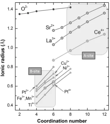
The distinct size – coordination number requirement for the two sites is outlined in Figure 2.4 which presents a plot of ionic radii against coordination number for some cations typically encountered in perovskites.10
[image:44.595.219.405.393.602.2]It is obvious from this plot that the A-site cations and the B-site cations cluster in distinct domains which do not intersect.
Figure 2.4 – Ionic radii vs. coordination number for some cations typically encountered in perovskites. The characteristic regions for A and B-site cations are emphasized and labelled.
Ionic radii from Shannon.11
44
because of the similar size of the constituting cations and this in turn causes difficulty in identifying which site is occupied by which cation.
Secondly, assuming the dopant is of the right size for the chosen site, it will, most likely, still have different volume compared to the cation being replaced. The means through which the perovskite lattice accommodates size mismatch is discussed below in relation to the so called tolerance factor, τ:
τ= rAO
√2∙rBO =
rA+ rO √2∙(rB+ rO)
τ is defined as the mismatch between the A–O and B–O bond lengths which are calculated as the sums of empirical ionic radii (rA, rB, rO) obtained from
X-ray diffraction at room temperature and atmospheric pressure.11 When
multiple cations occupy the same site, the average of their ionic radii is used. The tolerance factor is derived from the geometry of the perovskite cell and it represents a measure of how far away in terms of size are the constituting cations in order to create a perfectly cubic cell (see Figure 2.3 a).
τ > 1 τ < 1
(a) (b)In-phase tilting (c)Out-of-phase tilting
Figure 2.5 – Accommodation of cation substitution in perovskites. For τ > 1, the BO6
octahedra are slightly stretched, allowing for displacement of the B-site ion from its symmetry position as shown in (a). For τ < 1, octahedra undergo a cooperative tilting that with respect to the adjacent layer can occur in the same direction which is known as in-phase tilting (b), or in opposite direction and is called out-of-in-phase tilting (c).
For SrTiO3 the size of Sr2+ and Ti4+ are of just the right ratio to create a cubic
lattice and in consequence τ = 1. For τ > 1 the A-site cation is too large for the cuboctahedral cavity, therefore the TiO6 octahedra need to stretch
slightly in order to accommodate the A-site ion.9,12 Because of this, Ti is not
Ba
45
pinned any more in the symmetry centre of the octahedra and can move, potentially giving rise to ferroelectricity as in the case of BaTiO3 (rBa2+ > rSr2+) depicted in Figure 2.5 a.9,13 When size mismatch is even more
significant, hexagonal polytypes are produced.14
Situations when τ < 1 are encountered, for example, when substituting some Sr2+ by smaller cations such as La3+ or Ce4+/3+, and/or replacing some Ti4+ by
larger cations such as Fe3+, Zn2+ etc. In this case, the A-site cation is
undersized for the cuboctahedral cavity and thus it cannot make contact with all 12 oxide ions. The structure adjusts by undergoing cooperative rotations of the octahedra while maintaining both the regularity and the corner-sharing, a process that brings some of the oxide ions in touch with the small A-site cation. This is known as octahedral tilting and it has been the subject of many studies over the years.9,15–21 Octahedra in adjacent layers can tilt in the
same direction (in-phase tilting – see Figure 2.5 b) or in opposite direction
(out-of-phase tilting – see Figure 2.5 c), and with respect to all three
crystallographic directions (although some combinations are restricted, see ref 20).
There are two main consequences arising from octahedral tilting, aside from the overall decrease in symmetry that accompanies the process. Most importantly, the angle between Ti–O–Ti bonds drops from 180° as it is in the ideal structure to (180° – ϕ). ϕ usually increases with τ, but is typically not larger than 15° in titanates. This change in the Ti–O interactions (orbital overlap, inter-atomic distances etc) is expected to have a direct impact on many properties including the width of the conduction band, the band gap, or the strength of the Ti–O bond itself.14,22,23 Secondly, tilting leads to a
reduction in the coordination number of the A-site cation from 12 to 8-10, creating an asymmetric environment. This in turn may alter the diffusion pathways of the oxide ions and cause further splitting of the degeneracy.10 It
is worth noting that for most perovskites tilting gradually decreases with increasing temperature,19,24–29 such that at sufficiently high temperatures
46
the A–O bonds expand more than the B–O bonds with temperature,14,30 thus
if the perovskite starts with τ < 1, upon heating the numerator in Eq.2 will increase faster that the denominator, meaning that the tolerance factor can approach unity.
Although this description of tilting as an effect originating essentially from steric causes explains many observed phenomena,31 there have been
indications that increased covalent interactions between cations and anions would actually be the driving force behind tilting.9,32 Either way, the tilting
phenomenon is what makes the perovskite structure so easy to adapt and thus to be able to incorporate a wide variety of substitutions. Generally, the perovskite can accommodate cations by tilting such that 0.78 < τ < 1. Below this value, the ilmenite structure becomes more stable.9
The substitution level can also play an important role. When in small enough number, the dopants are randomly distributed on the host sites. However, if the doping level can lead to the formation of ordered structures then these structures will be preferred over the random ones. As a result, a large number of perovskites exhibiting A or B-site ordering are known.18,21,33
2.2.3 Accommodation of deficiency
Sub-stoichiometry (deficiency) is accommodated through the creation of vacancies in the perovskite lattice. Thus, the characteristic corner sharing connectivity of the BO6 octahedra is retained throughout the structure, but A
and/or O-sites vacancies are present. The incorporation of vacancies is often accompanied by tilting of the octahedra, most likely because vacancies behave as dopants of different size compared to the host.
The accomodation of A-site vacancies is illustrated in Figure 2.6 for the series
La𝑥Sr1−3𝑥 2⁄ TiO3. Until 𝑥 ~ 0.4, which corresponds to an A-site deficiency of
α = 0.2, the vacancies are randomly distributed in the perovskite, occasionaly associating into pairs (see Figure 2.6 b).25,34,35 Although the substitution
47
[image:48.595.135.469.283.615.2]from ideal (b), probably due to the similar size of the dopant and the host cation (Figure 2.4). As soon as more A-site vacancies are inserted into the structure by increasing La doping, 𝑥, they start to associate on a larger scale, eventually reaching a clear repetitive arrangement for 𝑥= 0.6 (Figure 2.6 c). The A-site species order in such a way that fully occupied planes alternate with planes that are only ~1/3 occupied. The octahedra are strongly tilted only around the 𝑥 axis which is perpendicular to the direction of cation-vacancy ordering. As it will be shown in Chapters 4 and 5, ordering plays a key role in the variation of properties.
Figure 2.6 – Accommodation of A-site deficiency and small oxygen deficiency in SrTiO3. (a)
The defect-free SrTiO3. (b) Randomly distributed A-site vacancies.25,35 (c) Cation-vacancy
ordering on the A-site.35,36 (d) Randomly distributed A, O-site vacancies (data from this
study, see Chapter 4).
Substituting Ni on the B-site of the 𝑥= 0.4 member of La𝑥Sr1−3𝑥 2⁄ TiO3,
which is accompanied by generation of vacancies, La𝑥Sr1−3𝑥 2⁄ Ni𝑦Ti1−𝑦O3−y,