Energy Efficient Secure Computation Offloading in
NOMA-based mMTC Networks for IoT
Shujun Han, Xiaodong Xu,
Senior Member, IEEE,
Sisai Fang, Yan Sun, Yue Cao,
Member, IEEE,
Xiaofeng Tao,
Senior Member, IEEE,
and Ping Zhang,
Fellow, IEEE
Abstract—In the era of Internet of Everything, massive connec-tivity and various demands of latency for Internet of Thing (IoT) devices will be supported by the massive Machine Type Com-munication (mMTC). Non-Orthogonal Multiple Access (NOMA) and Mobile Edge Computing (MEC) have the advantages of improving network capacity, reducing MTC devices’ (MTCDs) latency and enhancing Quality of Service. Exploiting these benefits, we focus on the energy efficient secure computation offloading in NOMA based mMTC networks for IoT, where the relay equipped with an MEC server and a passive malicious eavesdropper are presented. We optimize the joint computation and communication resource allocation to maximize the secrecy energy efficiency of computation offloading while guaranteeing the delay requirements of MTCDs. Furthermore, we model the subchannels allocation problem as MTCD-to-Subchannel match-ing. Exploiting difference of convex programming and successive convex approximation, we formulate the Dinkelbach-based SEE optimization algorithm and obtain the closed-form expression of power allocation for MTCDs’ on each subchannel. Based on the communication resources allocation schemes, we propose the Knapsack algorithm to solve the problem of computation resource allocation. Furthermore, we formulate the joint com-putation and communication resource allocation algorithm for secure computation offloading. Simulation results demonstrate the effectiveness of proposed algorithm for supporting IoT devices energy efficient secure computation offloading.
Index Terms—IoT, mMTC, NOMA, Mobile Edge Computing, secure energy efficiency, joint computation and communication resource allocation
I. INTRODUCTION
I
N the coming of the Internet of Everything era, hundreds of billions Internet of Things (IoT) devices will be connected to networks. Since the wide-area coverage capability, serviceCopyright (c) 2012 IEEE. Personal use of this material is permitted. However, permission to use this material for any other purposes must be obtained from the IEEE by sending a request to [email protected]. This paper is supported by National Key R&D Program of China No. 2017YFB0801702 and the National Natural Science Foundation of China No. 61871045 and 111 Project of China B16006. This works is also supported by BUPT Excellent Ph.D. Students Foundation CX2019308 and the China Scholarship Council. (Corresponding author: Xiaodong Xu)
Shujun Han, Xiaodong Xu, Sisai Fang, Xiaofeng Tao are with the Na-tional Engineering Laboratory for Mobile Network Technologies, Beijing University of Posts and Telecommunications, Beijing 100876, China (email: [email protected], [email protected], [email protected], [email protected]).
Yan Sun is with the Department of Electronic Engineering and Computer Science, Queen Mary University of London, London E1 4NS, U.K. (email: [email protected]).
Yue Cao is with the School of Computing and Communications, Lancaster University, UK. (email: [email protected]).
P. Zhang is with the State Key Laboratory of Networking and Switching Technology, Beijing University of Posts and Telecommunications, Beijing 100876, China (e-mail: [email protected]).
cost and scalability of cellular network, it fits well for large-scale IoT deployments that requires broader interconnection capabilities [1]. Especially, as the main foundation of IoT, massive machine type communication (mMTC) is considered to serve billions of IoT devices in 5G scenarios [2]–[6]. The mMTC refers to certain IoT scenarios, where a large amount of static sensors are deployed and report sporadically to an application server in the cloud [7], such as Vehicle Networks, Smart Meter Reading, E-health monitoring and Smart surveillance. Ericsson predicts that around 3.5 billion cellular IoT devices, i.e. MTC devices (MTCDs), will be widely deployed by 2023 [8].
Because of limited resources in computing, communication, storage and energy, it is hard for MTCDs to run sophisticated processing [9] and satisfy the quality of computation experi-ence in longtime working [10]. Soaring computing capabilities are required to improve the security, analytic and connectivity of MTCDs. However, the linear growth of cloud computing capabilities cannot match the explosive increasing in massive data that are collected from underlying MTCDs. Furthermore, the massive MTCDs data will stumble the cloud computing due to its shortcoming, such as high latency, security vulner-ability, low coverage, lagged data transmission and limited available bandwidth [11]. These noticeable challenges drive the IoT data to be processed close to where it is produced without being placed in a public cloud.
As a natural development in the evolution of mobile base stations and the convergence of information technology and telecommunications networking, mobile edge comput-ing (MEC) was proposed by European Telecommunications Standards Institute (ETSI) [12], which will be the impor-tant enabler to inspire the development of myriads of MTC applications and services. It aims at pushing traffic, cloud computing capabilities and network functions towards the edge of cellular networks. The International Data Corpora-tion predicts that 40% initial IoT data need to be analyzed, processed and stored at the edge of the network by 2019, and IoT will generate 95% of the real-time data by 2025 [13]. With characteristics of MEC in low latency, proximity, high bandwidth, location awareness and real-time insight into radio networks information, massive data generated by MTCDs can be efficiently executed by MEC server nearby the data sources. This will reduce the congestions in core networks, improve resource efficiency, increase the security of sensitive data and significantly simplify the functionality of MTCDs to make MTCDs cost efficiency.
com-munication resources [16], [17] will be a potential bottleneck for supporting massive MTCDs in MEC. The MTCDs are normally with low power and small size, which is traded off by sacrificing their computing performance, while the compu-tation tasks are generally intensive and latency-critical [18]. Although there are ultra-dense edge devices in 5G wireless systems, including small-cell base stations, wireless access points, laptops, tablets and smartphones, each of them are with limited computation resource. It may lead to Quality of Service degradation when many MTCDs computation offloading to one edge devices. In this case, the execution time in MEC server is non-negligible [19], because the less computation resource allocated to the MTCDs may cause the violation of their delay requirements. Furthermore, the limited available spectrum resources also cannot accommodate massive MTCDs to simultaneously connect the cellular networks for compu-tation offloading or communication, due to the traditional cellular network is mainly designed for traditional human to human communication, rather not mMTC.
Security is another critical requirements of supporting MTCDs in MEC [20], [21]. Although MEC offers a more secure infrastructure than cloud computing, but it still has its specific security and privacy challenges due to its unique features. Due to the innate heterogeneity of MEC system, the conventional trust and authentication mechanisms are inappli-cable [22]. Moreover, the traditional cryptographic techniques and associated protocols are usually not computationally af-fordable for MTCDs (e.g., sensors in smart grid) [23]. Unlike the wired connections in cloud computing, the computation tasks offloaded from MTCDs to MEC servers via wireless channel are more vulnerable to potential attacks due to the broadcast natures of wireless communications. In worst case, the MEC server may be a potential eavesdropping or jamming attacker at the physical layer. For example, the malicious attackers with tremendous processing power can decipher the data overheard from MTCDs for launching security attacks, especially, the data contains sensitive and private information. Instead of orthogonal multiple access, non-orthogonal mul-tiple access (NOMA) has been adopted into 5G New Ra-dio by 3rd Generation Partnership Project (3GPP) [24] and investigated by researchers in [25]–[28]. The NOMA not only supports multiple MTCDs computation offloading in the same resource concurrently [25], [26], it is also a diversity-assisted security approaches of improving the security for MTCDs computation offloading by exploiting the physical characteristics of wireless channels [27], [28]. In order to effectively protect computation offloading against eavesdrop-per attacks, the finite computation-communication resources should be well allocated in NOMA-based MEC to minimizing the computation offloading rate of the wiretap channel, while maximizing the computation offloading rate of the main chan-nel. However, none of studies have investigated the energy efficient secure computation offloading with consideration of joint computation-communication resource allocation in NOMA-based mMTC networks.
Due to MTCDs generally have strictly limited hardware and signal processing capabilities, limited storage capacity and significant energy constraints, they may not have the ability
TABLE I
NOTATIONSUSED INTHISPAPER
Notions Meanings
M,N set of MTCDs and subchannels
M,N,fT MTCDs/subchannels/computing capacity number
Nn maximum number of MTCDs in subchanneln
Mn the number of MTCDs in subchanneln
hdm,n,hem,n,gRn,gne channel gain
f
ge
n,^hem,n estimated CSI ofgenandhem,n
∆ge
n,∆hem,n estimated error
Im,n,d,Im,n,e interference and noise
pm,n,qn transmission power in subchanneln
Pm,max,PB,max maximum transmission power
xm,n subchannel allocation index
tT
m,tCm,tRm offloading time/execute time/receiving time
Lm,Km data of computation offloading task/workload
Dm maximum tolerable delay
P∗
M,X∗M,YM∗ optimal power/subchannel allocation matrix
Y∗M optimal computing resource allocation matrix
q∗
B optimal power allocation matrix of R-MECS
Ψ∗ optimal secrecy energy efficiency
λ, θ, ς Lagrange multiplier, power amplifier
ρ coefficient of residual self-interference power ∇xF, ∂F gradient of F of x, partial differential of F mMTC massive Machine Type Communication
MTCDs MTC devices
NOMA Non-Orthogonal Multiple Access MEC Mobile Edge Computing
R-MECS relay equipped with an MEC server CRB computation resource block
SEE, SR secrecy energy efficiency, secrecy rate DC difference of convex
to implement traditional cryptographic protocols. Physical-layer security [29] aims at reinforcing the security (i.e., data confidentiality) of communication systems by exploit-ing differences in channel conditions to prevent decodexploit-ing of messages from unauthorized users. Based on the secrecy capacity defined by Wyner [30], the data confidentiality can be guarantee if the achieved secrecy capacity is a positive value. Therefore, by comparing the security requirements of MTCDs and the potential benefits of physical-layer security, we see that physical-layer security methods can complement or even replace conventional cryptographic protocols as promising solutions for mMTC.
In this paper, we study the physical layer security enhance-ment for MTCDs computation offloading under eavesdropping attacks in the NOMA-based mMTC networks, which supports massive connectivity for MTCDs secure computation offload-ing. Exploiting the various delay requirements of MTCDs (cellular IoT devices), we joint allocate the finite computation-communication resources to MTCDs for achieving energy efficient secure computation offloading of IoT in NOMA based mMTC networks. Our main contributions are summarized as follows:
computation offloading.
2) Taking the various delay requirements of MTCDs and finite computation-communication resources into consid-eration, we jointly optimize the computation resources, MTCDs’ transmission power and subchannel allocations to maximize the SEE of system computation offloading. 3) We formulate the MTCD-to-Subchannel matching algo-rithm and Dinkelbach-based SEE optimization algoalgo-rithm to solve the communication resource allocation problem, and obtain the closed-from expressions of power alloca-tion for MTCDs on each subchannel. Furthermore, we solve the computation resource allocation problem by Knapsack algorithm.
The rest of this paper is organized as follows. In section II, we review the related works. In section III, we introduce the IoT secure computation offloading with R-MECS assisted in NOMA based mMTC networks. In section IV, we for-mulate the SEE maximization problem for IoT computation offloading. Joint resources allocation for maximizing SEE is formulated in section V. Furthermore, solution of power allocation scheme is given in VI. Simulation results and conclusions are presented in section VII and VIII, respectively. Notations used in this paper are listed in Table I.
II. RELATEDWORKS
The myriads of interconnected MTCDs has a significant surge in demand for computation resources. MEC and IoT facilitate each other with mutual advantages [31]. IoT ex-pands MEC services from smart meters to smart manufacture. Similarly, MEC enhances the computational capacity of IoT devices while saving their battery energies. MEC servers performed as a gateway aggregate, classify and process the data collected by IoT devices through computation offloading, rather than directly transmitting them to the core networks [32]. However, because of the synergistic nature of MEC based on both communication and computation, computing offloading is not beneficial for all IoT devices. Its limited resources may lead the computation offloading with a large execution delay due to the waiting execution time at the servers or the communication delay from MTCDs to servers. Therefore, it is important to balance the delay and energy consumption in computation offloading with limited resources constrains. The tradeoff between shortening execution time and extending battery life of devices is investigated in [33]. Furthermore, based on Lyapunov optimization, the authors proposed an energy-efficient offloading-decision algorithm to balance the energy-delay tradeoff based on the criteria of minimum response time or energy consumption [34].
Because separately optimizing the allocation of either com-putation or communication resource is highly suboptimal, joint optimization of radio and compute resources are studied in [35]. Taking infinite and finite computation capacity into consideration, You e.t. al [35] proved that the optimal re-source allocation policy have a threshold-based structure with respect to a derived offloading priority function, which yields priorities for users according to their channel gains and local computing energy consumption. Since massive MTCDs are
equipped with certain local computation and communication resources, enable user cooperation among these devices in both computation and communication is an efficient solution to improve the MEC performance. The multi-user cooperative MEC system are investigated in [36], where the limited resources MTCDs can offload intensive computation tasks to multiple nearby edge devices serving as helpers for remote execution. Exploiting the benefits of NOMA based MEC in supporting more MTCDs computation offloading with lower latency and energy consumption, a group of MTCDs form a NOMA cluster and simultaneously offload their computation tasks to MEC server over the same subchannel [37].
Achieving security between IoT devices and MEC servers is challenging, and both physical-layer and higher-layer security mechanisms can be applied to protect the offloading process [38]–[43]. Considered the eavesdropping attack when IoT devices offloading computation tasks to MEC servers over radio frequency channels, resource management for secrecy capacity enhancement in OFDMA and NOMA is investigated [38] [39]. Due to the limited attraction of traditional spectrum-expansion-based schemes for the spectrum-scarce IoT devices, the collaborative information sharing of IoT devices for online security-aware computation offloading is studied in [40] to resist the jamming attacks. Furthermore, exploiting the loca-tion informaloca-tion related to the attack, the [42] formulate a deep-learning based unsupervised learning model to automate detect the security threats at the edge of cellular networks. To overcome the high computation costs, low flexibility in key management, and low compatibility in deploying new security algorithms in IoT, the near-user edge device is employed as a security agent to simplify key management and offload the computational costs of security algorithms at IoT devices [43]. Ensuring security and privacy in IoT is particularly com-plicated, especially for the resource-constrained IoT devices. Therefore, integration of security mechanisms should be bet-ter included in the MEC architecture, which has not been addressed adequately in above researches. Although joint computation and communication resources allocation [33]– [36] and NOMA-based MEC system have been studied [25], [26], [37], they have rarely considered the security problem in computation offloading procedure, nor investigated the joint resources allocation problem to guarantee the energy effi-cient secure computation offloading in NOMA-based mMTC networks. Therefore, to fully gain the benefits of MEC and NOMA in mMTC networks, it is essential to study the maximization energy efficiency technology while ensuring the secure computation offloading of IoT devices.
III. R-MECS ASSISTEDUPLINKNOMA-BASED MMTC NETWORKMODEL
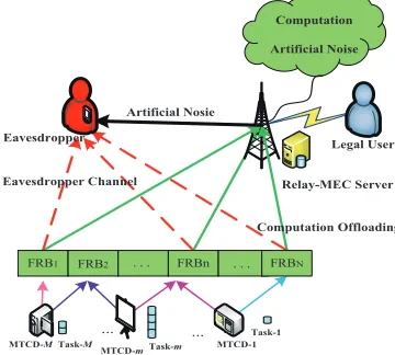
As illustrated in Fig.1, we consider the Relay with a R-MECS assisted computing mMTC network, where a setM,
{1, . . . , M} of MTCDs, an eavesdropper and a legal receive
computation results to the legal user. The procedure is named as cooperative computing and forwarding. The eavesdrop-per is passive and intercepts the information from MTCDs. All MTCDs are uniformly distributed within a cell range and equipped with a single antenna. Moreover, we consider NOMA as an access method. Although multiple MTCDs can share the same subchannel at the same time, they have to suffer from co-channel interference from the shared MTCDs.
$UWLILFLDO1RVLH
&RPSXWDWLRQ
$UWLILFLDO1RLVH
07&'m7DVNm
07&'M7DVNM 07&'
7DVN
5HOD\0(&6HUYHU
&RPSXWDWLRQ2IIORDGLQJ (DYHVGURSSHU&KDQQHO
(DYHVGURSSHU /HJDO8VHU
[image:4.612.86.266.168.330.2])5% )5% )5%Q )5%1
Fig. 1. IoT devices secure computation offloading with R-MECS assisted in NOMA-based mMTC networks
The cooperative computing and forwarding procedure has two stages: secure computation tasks offloading and secure computation results forwarding. In the stage of secure com-putation tasks offloading, the R-MECS works in full-duplex mode, which has the capability not only to receive the original data from MTCDs through wireless channels and to execute the computation tasks on behalf of the MTCDs, but also to suppress the eavesdropping by transmitting artificial noise to eavesdropper. In the stage of secure computation results forwarding, the R-MECS has enough capability to encrypt the computation results and secure forward them to the destina-tion, which is beyond of the focus in this paper and do not considered.
The computation tasks atm-th MTCD are characterized by
(Lm, Km, Dm).Lmis the data size of computation offloading
task.Kmis the workload ofm-th MTCD and measured by the
number of CPU cycles required to complete the execution of the task, which is application-dependent. Dm is the tolerable
delay of m-th MTCD, that is the data should be processed within this time. In practical, the available computation ca-pacity of R-MECS is limited with small-scale [14], [15], [35]. Hence, we assume that the computation capacity of R-MECS is divided into NC different computation resource
blocks (CRBs), and each CRB is equal to C CPU cycles per second [37]. The computation resources made available by the R-MECS and to be shared among the MTCDs are quantified by the computational capacity fT, expressed as numbers of
CPU cycles per second.
The available system bandwidth is shared by the MTCDs using NOMA to support more MTCDs computation offloading at the same time. The NOMA channel composes of N
subchannels, denoted by N ={1, . . . , N}, and each has a bandwidth B. The noise power at the receiver of the R-MECS is denoted asσ2. The R-MECS exploits its full-duplex
capability to conduct artificial noise to eavesdropper. However, it also negatively influences itself in receiving information from MTCDs, known as self-interference. We denote the self-interference channel gain in n-th subchannel as gR
n, and
the channel gain from R-MECS to eavesdropper in n-th subchannel is gen. The channel gains from m-th MTCD to R-MECS (destination) and eavesdropper in subchannel nare denoted byhdm,nandhem,n, respectively. We assume that the
R-MECS perfectly knows the channel state information and the computation information of all MTCDs, but only partially knows that ofge
n andhem,n.
As commonly adopted in the physical-layer security lit-eratures [38], we consider the deterministic CSI uncertainty model for ge
n and hem,n, where gne = gfen + ∆gen and
hem,n = h]em,n+∆hm,ne . gfen and h]em,n denote the estimated
CSI of ge
n and hem,nat the R-MECS, in addition, ∆gen and
∆he
m,n denote the estimated error that is bounded by a
possible value ε ≥ 0 as |∆ge n| ≤ ε,
∆he
m,n
≤ ε. gne and hem,n are the best possible channel gain of the eavesdropper known by the R-MECS, and ε is also known by R-MECS. Moreover, both distance dependent path loss and Rayleigh fading on each of the subchannel are considered, such that
hdm,n = Dd
−α/2
m,d ~ d
m,n and h]em,n = Dd
−α/2
m,e ~em,n, where
Ddm,d and Ddm,e are the distances from MTCD m to
R-MECS (destination) and eavesdropper.αdenotes the path-loss exponent and~dm,n,~em,n∼ CN(0,1) denote the normalized
Rayleigh fading. The block fading model is adopted, where all the subchannels are invariable during a complete transmission cycle and the co-channel interference among MTCDs on each subchannel is considered.
IV. SECURECOMPUTATIONOFFLOADING OVER NOMA-BASED MMTC NETWORKS
A. Secure Computation Offloading Energy Efficiency
In R-MECS assisted computing mMTC system, each MTCD offload their computation tasks to R-MECS by using different subchannels, and each subchannel can be shared by more than one MTCD simultaneously with actively introduc-ing interferences. To reduce the complexity of receiver, an upper limitation of the number of sharing same subchan-nel is givenPM
m=1xm,n ≤ Nn, m ∈ M, n ∈ N where
xm,n= 1 denote the n-th subchannel is assigned to the m
-th MTCD,o-therwisexm,n= 0.
When R-MECS works in full-duplex mode, it will bring self-interference to its receiver and cannot be canceled com-pletely due to the hardware limitation. We describe the residual self-interference with the self-interference channel gaingR
n as
a linear coefficientρ[44]. The residual self-interference inn-th subchannel is denoted asρqn
gRn
2
, andqnis the transmission
power from R-MECS to eavesdropper in subchannel n. Spe-cially, for the self-interference, we assume EngR
n
2o = 1,
n∈ N.
order in destination channel and eavesdropping channel. The achievable secrecy rate and lavage information rate in eaves-dropper of the m-th MTCD in then-th subchannel are given by,
rm,n,d=xm,nBlog2(1 +γm,n,d)
rm,n,e=xm,nBlog2(1 +γm,n,e)
(1)
γm,n,d and γm,n,e are the signal-to-noise-plus-interference
ratio (SINR), particularly, they are evaluated by
γm,n,d=
pm,n
hd
m,n
2
σ2+PM
i=m+1pi,n
hd
i,n
2
+ρqn|gnR|
2
γm,n,e=
pm,n
he
m,n
2
σ2+PM
i0=m+1pi0,n h
e i0,n
2
+qn|gen|
2
(2)
The computation offloading rate in the n-th subchannel of MTCD-to-R-MECS and that of then-th subchannel in MTCD-to-eavesdropper are given by
rn,d=
XMn
m=1rm,n,d, rn,e=
XMn
m=1rm,n,e (3)
Furthermore, the maximum achievable computation offloading secrecy rate (SR) of each MTCD is given by the difference of the MTCD-to-R-MECS computation offloading rate and the MTCD-to-eavesdropper computation offloading rate, which can be expressed as
USC =
XN
n=1[rn,d−rn,e] +
(4) Due to the low-cost and power-limited features of MTCDs, a major concern is to secure computation offloading with limited power and energy as much as possible. The performance metric of secrecy energy efficiency (SEE) for computation offloading needs to be maximized, which is defined as the total number of secure computation offloading bits per Joule from the MTCDs to R-MECS. The SEE of all uplink system is defined as
SEE=USC
UT P
(5)
which is the ratio of the total SR to the total energy consump-tion.UT P is the total power consumption of all MTCDs, and
can be expressed as
UT P =
XN
n=1
XMn
m=1 1
ςxm,npm,n+PC
(6)
The transmission power consumption of m-th MTCD is
PN
n=1xm,npm,n, which is not the only component to calculate
SEE for computation offloading, static circuit power consump-tionPCalso plays a significant role of SEE and includes circuit power and processing power. ς ∈ [0,1] is a constant value which accounts for the power amplifier efficiency.
B. MEC Server Scheduling
The maximum tolerable delayDmofm-th MTCD
incorpo-rates the time of offloading tasks to MEC server for executing, which are the time for computation tasks offloading from m -th MTCD to MEC server tTm, the time necessary for MEC
server executing tC
m and the time for legal user receiving
computed results tR
m. In other word, tTm+tmC+tRm ≤ Dm,
where tT m =
Lm
Rm SC
, tC m =
LmKm
ym . ym represents computing
resources assigned to m-th MTCD, and they are subject to the computational budget constraintPM
m=1ym≤fT.
In general, R-MECS has enough energy to transmit com-putation results with small size to legal users, we assume that the time for legal users to receive the computed results is negligible [26], i.e., tR
m= 0. Thus, the total secure
computa-tion offloading time and execucomputa-tion time ofm-th MTCD’s task should be no larger than its maximum tolerable delay Dm
tTm+tCm≤Dm (7)
The maximum tolerable delay constraint in (7) is what cou-ples computation and communication optimization variables, which motivates a joint optimization of computation resource and communication resource. The total execution time in (7) is equivalent to the following minimum computation offloading SR requirement USCm ≥ Lm
Dm−tCm where t
C
m < Dm. Due to
the constraints of the minimum computation offloading SR, the overall network performance in terms of SEE may be degraded.
C. Optimization Problem Formulation
The power allocation scheme of MTCDsP∗M , subchannel allocation schemeX∗M, computation resource allocationYM∗
and the transmission power allocation of R-MECSq*
B can be
obtained by solving
P1 max
xm,n,ym,pm,n,qn
SEE
s.t. C1 :RmSC ≥ Lm
Dm−tCm
, m∈ M
C2 :tCm< Dm, m∈ M
C3 :XM
m=1xm,n≤Nn, m∈ M, n∈ N
C4 :xm,n(xm,n−1) = 0, m∈ M, n∈ N
C5 :XM
m=1ym≤fT, m∈ M
C6 :XN
n=1qn ≤PB,max, n∈ N
C7 :XN
n=1xm,npm,n≤Pm,max, m∈ M
C8 :qn≥0, n∈ N
C9 :pm,n≥0, m∈ M, n∈ N
(8)
where C1 represents the minimum computation offloading SR requirements for each MTCD to meet the maximum tolerable delay constraint; C2 imposes a limitation on the task execution time tC
m with the delay limitation Dm; C3 ensures the total
number of MTCDs sharing the same subchannel is not exceed
Nn and C4 restricts xm,n is a binary variable; C5 is the
limitation of the computation resource in MEC server available to the MTCDs, C6 and C7 are the power budget constraints of R-MECS and MTCDs, respectively; Moreover, C8 and C9 guarantee the transmission power of R-MECS and MTCDs to be positive values.
&RQYHUJH
RU l!LPD[
6WDUW
(QG ,QLWLDOL]DWLRQ
SDUDPHWHUV
&RPSXWLQJDQG5DGLR 5HVRXUFHV$OORFDWLRQ
δ$OJRULWKPε
$OJRULWKP
1HZWRQ0HWKRG
&RQYHUJH PD[
l!L
RU
&RQYH[SURJUDPPLQJ
$OJRULWKP
&RQYHUJH RU
l l
M B
3 T
M B
3 T
$OJRULWKP $OJRULWKP
B
B B
B
L n
n n
L n
c
T
T T T
&RQYHUJH
RU l!LPD[ l!LPD[
&RQYHUJH RU
PD[
l !L
M B M
3 T ;
M B M
3 T ;
M B M M
3 T ; <
1R
1R $
B T
<HV 1R
1R 1R
1R
<HV
<HV <HV
<HV
&RQYHUJH
[image:6.612.80.535.58.253.2]RU l!LPD[
Fig. 2. The Relationship between the Following Proposed Algorithm
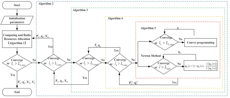
accommodated. The C1-C9 can be enforced by a proper admission control scheme through solving P1. However, the introduced co-channel interference in NOMA system leads a coupling among all MTCDs, which makes the objective function in P1 is a ratio between a nonconvex function and an affine function. In addition, the subchannel indicator is binary variable. Thus,P1is classified into a non-convex mixed integer nonlinear fractional programming problem, which is non-polynomial problem. The optimal SEE depends now on both computation and communication parameters, such as maximum tolerable delay, input size of MTCDs, CPU cycle budget of R-MECS, etc. Different from the classical secure transmission in P1, each MTCD’s secure computation offloading rate has to meet the latency constraint in (7), which means that a lowest secrecy computation offloading rate is no longer optimal. Therefore, we develop computationally efficient algorithms for SEE maximization problem suitable to uplink NOMA-based mMTC systems. To clearly express the relationship among the following proposed algorithms, we make a high-level illustrative representation as shown in Fig.2.
V. JOINTRESOURCESALLOCATION FORMAXIMIZING SEE
In this section, we will give a overview of the SEE maximization scheme, which is obtained upon a two stages resource allocation algorithm. In the first stage, SEE with communication resource allocation is solved by an iterative algorithm of joint subchannel and power allocation, where subchannel allocation is solved by Match Game and power allocation algorithm is obtained from fractional programming and DC programming. The iterative radio resources allocation for maximizing SEE is given in Algorithm 2, which is to solve P2. In the second stage, to take full use of computation resource and maximize SEE, the optimization problem of computation resource allocation shown in P3 is modeled as a dynamic programming and solved by Knapsack algorithm, which is illustrated inAlgorithm 1.
A. Knapsack-based Algorithm to Maximize SEE
Because MTCDs are energy-critical devices in mMTC net-works, it is meaningful to discuss the relationship between SEE and secure computation offloading time, and in order to exploit the various delay requirements of MTCDs to prolong the lifetime of MTCDs.
Theorem 1. The SEE of m-th MTCD is monotonically
in-creasing and convex in its secure computation offloading time tT
m.
Proof:It can be seen in Appendix A.
Therefore, making full use of the various delay requirements of MTCDs can effectively improve the SEE of uplink compu-tation offloading mMTC networks. Since the offloading tasks must be offloaded to R-MECS within given amount of time and little execution time left cannot complete the computation tasks in R-MECS, the secure computation offloading time of any computation task cannot be arbitrarily long. However, constrained by limited computing resources in R-MECS, each MTCD wants to be assigned as more computing resources as possible, which will reduce the execution time and increase secure computation offloading time under delay requirement. It is essential to reasonable allocate the computing resources to maximize SEE.
We take the confidential of computation tasks into con-sideration in our proposed Knapsack problem. Moreover, the joint computation and communication resource allocation for maximizing SEE problem is reformulated as a Knapsack problem, which optimizes the communication resource alloca-tion scheme with computaalloca-tion resource constraints taken into consideration,
P2 max
xm,n,pm,n,qn
SEE
s.t. C3-C4,C6-C9
f
C1 :SRm≥
Lm
Dm
=Rm,min
and
P3 max
ym
YM
s.t. ym≥
LmKm
Dm−SRLm
m
,∀m∈ M
C2,C5
(10)
whereSRm=P N
n=1[rm,n,d−rm,n,e]
+
,η(YM)=SEE.
In the proposed Knapsack problem, the R-MECS is seen as a knapsack and the computation capacity in C5 is the volume of knapsack. The computation resourceymrequired by them
-th MTCD represents -the volume goods to be packed into -the knapsack and the computation offloading SEE achieved by the
m-th MTCD is the value of corresponding goodsym. Different
from the Knapsack algorithm in existing researches to solve the problem of computation resource allocation, the goods have its value only when the required MTCD can guarantee the confidential of computation tasks, i.e., the computation offloading SEE achieved by the MTCD has a positive value.
Algorithm 1: Joint Resource Allocation for Maximizing SEE Input:PM,XM,qB,{Dm, Lm},Nn,Nc
Output:SEE*
1:While|SEE(l1)−SEE(l1−1)|> ε1 orl2≤L1,max 2: Calculate SEE based on the iterative communication resource
allocation for maximizing SEE algorithm (inAlgorithm 2). 3: Based onC1, calculate the required computing resourcesf ym 4: Perform computing resources allocation based on the
Knapsack algorithm. 5:End While
TheP2in (9) is a non-convex mixed integer non-linear pro-gramming (MINLP) problem due the product termxm,npm,n
in objective and constraints of P2, where xm,n is a binary
variable. The MINLP problem is known to belong to NP-hard problems and no efficient solutions exists because the com-plexity may increase exponentially with problem size. This type of problems is among the most challenging problems, and obtaining the globally optimal solution is intractable for mMTC networks. In this section, instead of directly solving the MINLP problem, we transform the optimization problem into MTCD-to-subchannel matching subproblem and power allocation subproblem.
Algorithm 2: Iterative Communication Resource Allocation for Maximizing SEE
Input: maximum toleranceε2and maximum iterationsL2,max Output: optimal secure energy efficientSEE∗
1. Initialization : the powerpm,nfor each MTCD andqnfor R-MECS 2:While|SEE(l2)−SEE(l2−1)|> ε2orl2≤L2,max
3: Given the power allocation, updatexm,nbased onAlgorithm 3 4: Reallocatepm,nandqnaccording toAlgorithm 4.
5: Setl2=l2+ 1and calculateSEE(l2+ 1). 6:End While
By iteratively solving the two sub-problems, the system SEE slightly improves at each iteration and will converge at last, the detail procedure is presented in Algorithm 2. It finds at least a locally optimal solution with polynomial time, which has the potential to be a global optimum.
B. MTCD-to-Subchannel Matching Problem
The optimal solution XM of P2 can only be obtained by
performing an exhaustive search over all subchannel XM =
[xm,n] that respect the C3 and C4 in P2. There are at least
MN different subchannel allocation matrices to be evaluated,
which greatly increased the processing time in MTCD and the computing complexities in MEC server grow fast with the number of MTCDs. In the subchannel allocation process, the MTCDs prefers to access the subchannel with good quality to achieve the best service, while the subchannel allocation aims at maximizing the system SEE by arranging right MTCDs using the subchannels. Thus, in this section, we model the subchannel allocation problem as a matching process where MTCDs and subchannels match with each other to maximize the system SEE.
Algorithm 3: MTCD-to-Subchannel Matching Algorithm Input:pm,n,ym,qn,Nn
Output:optimal subchannel allocation matrixX∗
M
1: Initialization Phase(Subchannel Selection) Initialize the set of unmatched subchannelsΩu For each MTCD
CalculateSEEm,n of each unmatched subchannel Construct the preferable listPMD(m)based onSEEm,n End
2: Matching Phase(Subchannel Allocation) For each MTCDm
If the proposal set ofm-th MTCDPMD(m)6=∅ m-th MTCD propose itself to its preferable unmatched
subchannel according toPMD(m)
For each unmatchedn-th subchannel
Ifn-th subchannel has received proposal from MTCDm-th Accept the proposal fromm-th MTCD
End If
For each MTCD favors ton-th subchannel
Construct the preferable listPSC(n)based on SEE of the accepted MTCDs
Assign subchanneln-th to its favorite MTCD with maximum SEE and setxi,n= 1
End For
3: Updating Phase(Unmatched Subchannels Updating) For each unmatchedn-th subchannel
IfPM
m=1xm,n=Nn
Ωu=Ωu− {n} End If
End For
Let(MTCDm, SCn)denote a matching pair if subchannel
n is assigned to m-th MTCD. The unmatched MTCD set is Ωu. The preferable matrix PMD of MTCDs record their
preferable subchannel sequence ranked by affordable SEE in each subchannel, i.e.SEEm,n. The preferable matrixPMD
is constructed at the beginning of the matching, and will not be changed throughout the matching process. It guarantees the matching algorithm is low complexity and operability, and is same as the conventional Gale-Shapley algorithm. However, the preferable matrix PSC based on the achieved secure energy efficiency SEEn on itself are unreducible in static
matching iterations, because there is interdependence relation-ship between the MTCDs who share the same subchannel in matching algorithm. To further reduce the complexity, the preferable matrix PSCof subchannels is not constructed in advance.
their preferable matrixPSCbased on the SEE of each MTCD. The subchannel will assign its favorite MTCD with maximum SEE to sharing itself, and the unassigned MTCD on this subchannel will reselect the new subchannel. The detailed entire process of MTCD-Subchannel matching algorithm are described in Algorithm 3, which consist of initialization phase, matching phase and updating phase.
C. Power Allocation Algorithm for Maximizing SEE
Without loss of generality, we define the maximum SEE, of P2in (13) as Ψ*. Based on the fractional programming , the primary problem is associated with a parametric program problem stated as follows,
Ψ∗= USC(P
∗
M,q
∗
B)
UT P (P∗M,q∗B)
= max
{pm,n,qn}
USC(PM,qB)
UT P(PM,qB)
(11)
Theorem 2. The maximum SEE can be achieved only when
Ψ∗m and the optimal resource allocation policies {P∗m,q∗B}
satisfy,
max
{pm,n,qn}
USC(PM,qB)−Ψ*UT P(PM,qB)
=USC(P∗M,q∗B)−Ψ*UT P(P∗M,q∗B)
= 0
(12)
Proof: It can be seen in Appendix B.
To solving (12) with an equivalent objective function, we propose a Dinkelbach-based SEE optimization algorithm, which is shown in Algorithm 4. The iterative approach presented in the Dinkelbach-based SEE optimization algorithm provides closer approximations to the optimal SEE at each iteration, stopping when a fixed convergence error ε4 or
the maximum of iterations L4,SEE is achieved. The objective function at the process of iteration of the Dinkelbach algorithm is written as
P4 max
{pm,n,qn}
USC(PM,qB)−Ψ(l)UT P (PM,qB)
s.t. C6-C9
f
C1 :SRm≥Rm,min, m∈ M
(13)
whereΨ(l)is the temporary parameter used in thelthiteration of Dinkelbach algorithm.
Algorithm 4: Dinkelbach-based SEE Optimization Algorithm Input:ε4andL4,maxandl4= 0
Output:Ψ* andP∗
m Ψ*
,q∗B Ψ*
1. Initialization :L4,SEE,ε4,Ψ(0)=0, 2: Repeat
3: Obtain
n P(l4)
M ,q (l4)
B
o
byAlgorithm 5
4: IfUSC
P(l4)
M ,q (l4) B
−Ψ(l4−1)UT P
P(l4)
M ,q (l4) B
< ε4 5: Convergence=ture
6: Return
P∗M,q∗B =
n
P(l)M,q(l4)
B
o
andΨ*=USC
P(l4 )
M ,q
(l4 )
B
UT P
P(Ml),q(Bl4 ) ;
7: Else
8: Convergence=false 9: SetΨ(l4+1)=USC
P(l4 )
M ,q
(l4 )
B
UT P
P(Ml4 ),q(Bl4 )
andl4=l4+ 1;
10: End if
11: Until Convergence=ture orl4=L4,max
VI. SOLUTIONS TOPOWERALLOCATIONSCHEME Although given the MTCD-to-Subchannel Matching scheme, USC(PM,qB) in optimization problem (18), the
sum of multiple rate function, is still non-convex optimization problem with respect to pm,n. In order to reduce the
complexity of solving the power allocation problem, SCA and DC programming are exploited to solve this problem. We first establish a concave lower bound of user rate, which is parameterized by a given power allocationPdM [45],
log2(1 +z)≥αlog2(z) +β (14)
whereα=1+ˆzˆz, β=log2(1 + ˆz)− zˆ
1+ˆzlog2(ˆz), and the equality
holds when z = ˆz. By exploiting the rate lower bound, the lower bound of data rate of the m-th MTCD-to-R-MECS and that of the m-th MTCD-to-eavesdropper on the n-th subchannel can be written as
˜
rm,n,d =Bαm,n,dlog2(˜γm,n,d(Am,n,qB)) +βm,n,d
˜
rm,n,e=Bαm,n,elog2(˜γm,n,e(Am,n,qB)) +βm,n,e
(15)
whereA=P*
M andr˜m,n,d(Am,n,qB)is a concave function
of Am,n, which is proved in [46]. We rewrite the P4as
P5 max
{pm,n,qn} g
USC(A,qB)−ΨUT P(A,qB)
s.t. C6 :f
XNf
n=1qn≤PB,max, n∈ Nf
f
C7 :XNf
n=1Am,n≤Pm,max, m∈ M
f
C8 :qn≥0, n∈ Nf
f
C9 :Am,n≥0, m∈ M, n∈ Nf
Co1:SR]m≥Rm,min, m∈ M
(16)
where the UgSC(A,qB)=P M m=1
PNf
n=1[˜rm,n,d−r˜m,n,e]
+
andSR]m(A,qB)=P N
n=1[˜rm,n,d−˜rm,n,e]
+
.
A. Dual Decomposition with the Fixed SEEΨ
Due to the nonconvex objective function and nonconvex feasible set ofP5, it is difficult to obtain the optimal solution. We intend to solve P5 by exploiting dual decomposition. In this way, the nonconvex constraint Co1 can be incorporated into the objective function and the feasible domain is turn into a convex set. Therefore, the DC programming can be exploited in the next subsection.
If the constraint Co1 is eliminated, the feasible domain of P4 will be convex and the problem will be decoupled. Thus, we construct the lagrangian function ofP5as
L(θ,A,qB) =UgSC(A,qB)−ΨUT P(A,qB)
+XM
m=1θm
]
SRm−Rm,min
(17)
The dual problem ofP5is written as
min
θ≥0A,maxqB∈S1
L(θ,A,qB) (18)
where λ ≥ 0 is the lagrange multiplier. Then, the feasi-ble domain of A,qB is turn into the convex set S1 = n
A:C6,f C8,f qB :C7,f C9f
o
The sub-gradient method can be applied to solve the higher level subproblem min
θ≥0L(θ,A,qB) of (24) with fixed A,qB. The gradient of L(θ,A,qB) with respect to θm is
PNf
n=1(˜rm,n,d−r˜m,n,e)−Rm,min, thus the dual variablesθm
can be updated by
θm(s+ 1) =θm(s)+φs
XNf
n=1(˜rm,n,d−˜rm,n,e)−Rm,min
(19) whereφs is the positive step size at thes-th iteration.
The lower level subproblem max
A,qB∈S1
L(θ,A,qB) can be
solved whenθ is fixed. However, due to the nonconvexity of
L(θ,A,qB)of bothAandqBsimultaneously, the lower level
subproblem max
A,qB∈S1
L(θ,A,qB) is still difficult to solve.
Therefore, with fixed Aor qB , the alternate search strategy
can be adopted to solve the lower problem. In alternate search, there is only one of A, qB optimized in every step while
others keeps fixed. In other words, we can find the solution by iteratively solving following problems
P6 min
qn
L(θ,A,qB)
s.t. C6,f C8f
(20a)
min
Am,n
L(θ,A,qB)
s.t. C7,f C9f
(20b)
With fixed θ, L(θ,A,qB) is a concave function of qB,
the proof of which is shown in Appendix C, but it is still not convex of A. Thus, the optimal value qB in (20a) can
be found by Newton method, while the optimal value A in (20b) can be obtained uniquely by DC programming in the next subsection.
B. DC Programming for Power Allocation
Although L(θ,A,qB) is not convex with respect to A,
the key idea of DC programming is to convert a non-convex problem to convex sub-problems by SCA and obtain a locally optimal solution. By exploiting the DC structures, we convert
L(θ,A,qB)as
L(θ,A,qB) =F1(A)−F2(A) (21)
where the function F1(A)andF2(A)can be expressed as
F1(A) =XN
n=1
XMn
m=1(θm,n+ 1)˜rm,n,d
−ΨXN
n=1
XMn
m=1 1
ςpm,n+pm,C
F2(A) =XN
n=1
XMn
m=1(θm,n+ 1)˜rm,n,e
(22)
The objective F1(A) and F2(A) are continuous concave function [46] on compact and convex set C7f and C9f, it
be-longs to DC function programming. Thus, (27b) can be solved uniquely by DC programming. Since F2(A) is DC function for any feasible point A(k), its convex majorant can be ex-pressed asF2(A)≈F2 A(k)+∇AF2T A(k)
A−A(k),
which is affine functions representing the global underestima-tion of F2(A).
Then, we can solve theP6by
P7 min
Am,n
LA(k)
s.t. C7,f C9f
(23)
The solution of DC programming problem in (23) is con-cluded in Algorithm 5. For differentiableF1(A)andF2(A), Algorithm 5 returns a stationary point of L(A), which is proved inAppendix D.
Algorithm 5: Successive Convex Approximation for DC problems Input:F1(A),F2 A(k),ε5,L5,max
Output:A∗
1. Initialization :k= 1,A(k) 2: Repeat
3: update the optimization problem with
Ak+1
and obtain
Ak+1 = arg min Am,n,qn
L(k)(Ak)
4: k←k+ 1
5: UntilL(A(k+1))−L(A(k))
≤ε5ork > L5,max
Although CVX can solve this problem, it will suffer from the curse-of-dimensionality problem as the number of both MTCDs and subchannels growing vastly. A Lagrangian Primal-Dual based algorithm is formulated to solve this prob-lem. Given the Lagrange multiplierλand SEEΨ, the optimal power allocation for them-th MTCD on subchannelncan be derived as
Am,n
= Cm,nαm,n,dA
(k)
m,n
Cm,nαm,n,e+ ln 2
Ψ1
ς+λm,n+
Pm−1
i=1 Bim,n
A(m,nk)
(24)
where
Bim,n=Ci,nαi,n,d
hd
m,n
2
ln 2Ii,n,d
−Ci,nαi,n,e he
m,n
2
ln 2Ii,n,e
Ci,n= (θi,n+ 1)W
Proof:The proof can be seen inAppendix E.
C. Computation Complexity of The Proposed Algorith,
The computational complexity of Algorithm 1 is the total computational complexity of the proposed scheme, which including the computational complexity of Algo-rithm 2 and that of Knapsack algoAlgo-rithm. The computational complexity of knapsack algorithm is O(M fT). The
com-putational complexity of Algorithm 3 is O(l3M N). The computational complexity of finding optimal q∗B in Algo-rithm 4 is O(lN), where l is the iterations of Newton method. The computational complexity of finding the op-timal P∗M in Algorithm 5 is O(M N l5). Thus, the total computational complexity of Algorithm 1 can be computed
asO(l1l2l3M N+l1l2l4l5M N+l1l2l4lN+l1M fT), where
l1, l2, l3, l4, l5 are the number of iterations in each algorithm.
TABLE II
SIMULATIONPARAMETERS
Parameter Value Range
Transmission bandwidth 10MHz
Number of subchannels 50
Bandwidth of one subchannel 180kHz
Distance dependent path loss 128.1+37.6log10(d) (dB), d (km) Shadowing standard deviation 8dB
Fading Rayleigh fading
Max MTCDs in same subchannelNn 2 Max transmission power of R-MECSPB,max 46dBm Max transmission power of MTCDPm,max 23dBm Static circuit powerPC 5dBm Power amplifier efficiencyς 0.38 coefficient of residual self-interferenceρ -110dB [44]
NoiseNo -90dBm [44]
Total computational Resource BlocksNC 30 [37]
Computing capacity of each RBC 10 Giga cycles/s [37] Workload of each MTCDKm [0.5,1]Giga cycles [37] Data size of computation tasks
for each MTCDLm [5000,7000] bits [37] Deadline of each MTCDDm [400,500] ms [37]
VII. PERFORMANCEEVALUATIONS
In this section, we evaluate the SEE performance in MEC assisted NOMA-based mMTC networks through Monte Carlo simulations. The system parameters used in simulations are given in Table II unless specificized stated, where the wireless parameters are referred to 3GPP standard [47]. As the R-MECS works in full-duplex mode, its effective distance is 150m, we consider one R-MECS located in the cell center and M users are uniformly distributed on the circular range with radius of 150 m. In the simulations, we consider a worse case and set the distance between base station and eavesdropper as 30m. In Orthogonal Frequency Division Multiple Access (OFDMA) systems, each user can only be assigned to one subchannel. In NOMA systems, the maximum users can be multiplexed on the same subchannel is Nn. Considering the
characteristic of MTCDs, we set the static circuit power of MTCDs as 5dBm.
1 2 3 4 5 6 7 8 9 10
1.5 2 2.5 3 3.5 4 4.5 5 5.5x 10
9
Iteration
Secure Energy Efficiency for Computation Offloading (bits/Joule)
[image:10.612.72.269.563.720.2]M=60 M=90 M=120
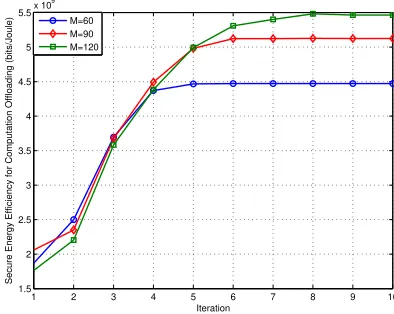
Fig. 3. SEE for Computation Offloading vs. number of iteration
The convergence behavior of proposed joint resources allo-cation for SEE algorithm is illustrated in Fig. 3. The proposed algorithm converges after 5 iteration when M = 60, via the update of computation resource allocation based on Knapsack algorithm and iterative communication resource allocation for maximizing SEE algorithm. With the increasing number of MTCDs, although more MTCDs will join the procedure of MTCD-to-Subchannel matching to maximize the SEE, the increased iterations of the proposed algorithm are limited and the total required iterations are not high.
We name the proposed joint resource allocation for max-imizing SEE algorithm applied in NOMA system as SEE-NOMA in Fig.3 and Fig.4. For convenience, we give the explanation of the compared schemes in [35] [37] [38] and other baseline schemes:
1) We take the offloading priority function scheme for users in each subchannel [35] as a compared scheme, which is based on the OFDMA system and called as SEE-OPF in the simulation results.
2) We take the proposed schemes in [37] as SEE-MENOMA, which aims to minimize the total energy con-sumption in NOMA based MEC computation offloading scenario.
3) Furthermore, we compare our proposed algorithm with the schemes in [38] and name it as SEE-MENOMA, which minimizes the energy consumption in OFDMA based system while guaranteing the secure computation offloading.
4) To study the effect of subchannel allocation, we name the proposed joint resource allocation for maximizing SEE applied in a conventional OFDMA system as SEE-OFDMA.
5) Moreover, we name the scheme of substituting random subchannel allocation algorithm for MTCD to subchannel matching algorithm in the proposed NOMA as SEE-RRB.
6) To study the the influence of computation resource al-location, we name the scheme of replacing Knapsack algorithm with the fractional computation resource (FCR) allocation methodym= PKMm
i=1KifT in the proposed
SEE-NOMA as SEE-FCR, wherefT = 300 Giga cycles/s is
the total computing resource.
7) We also compared our proposed SEE-NOMA algorithm with the joint resource allocation algorithm for maximiz-ing conventional computation offloadmaximiz-ing SR in NOMA system, which is shorted as SR-NOMA.
The performance of SEE versus the number of MTCDs is evaluated in Fig.4. The total number of MTCDs ranges from 30 to 150 and the upper limit number of MTCDs per subchannel is Nn = 2. As it can be seen from
schedul-ing. The performance of SEE-OPF [35] has lower SEE than that of SEE-NOMA and SEE-FCR, which means that offloading priority function scheme is not applicable for guarantee the secure energy efficient computation offloading. Furthermore, the SEE-MENOMA [37] and SEE-MEOFDMA [38] have worst performances in SEE, because they are not mainly designed for secure en-ergy efficient for computation offloading in NOMA-based mMTC networks.
30 60 90 120 150
Number of MTCDs 0
1 2 3 4 5 6
Secure Energy Efficiency Computation Offloading (bits/Joule)
109 SEE-NOMA SEE-FCR SEE-OFDMA SR-NOMA SEE-RRB SEE-OPF[35] SEE-MENOMA[37] SEE-MEOFDMA[38]
[image:11.612.75.271.185.342.2]3.437x109 bits/Joule, a gain of 193.3%
Fig. 4. Computation Offloading SEE vs. number of MTCDs
30 60 90 120 150
Number of MTCDs 0
0.5 1 1.5 2 2.5 3 3.5
Secure Rate for Computation Offloading (bits/s)
107 SEE-NOMA SEE-FCR SEE-OFDMA SR-NOMA SEE-RRB SEE-OPF[35] SEE-MENOMA[37] SEE-MEOFDMA[38]
0.671x107 bits/s, a loss of 24.74%
Fig. 5. Computation Offloading SR vs. number of MTCDs
The achieved SR of different schemes is also compared in Fig.5, where the simulation conditions are same with in Fig.4. The optimization goals of SR-NOMA is maximizing the SR while other schemes are maximizing SEE. Compared with the achieved SR of the SR maximization problem, the proposed SEE maximization leads to a certain loss of SR, especially the SR of proposed SEE-NOMA has a loss of 24.74%. However, the SEE of SEE-NOMA scheme has a gain of 193.30% compared with that of SR-NOMA (shown in Fig.4), which means that the SEE-NOMA will securely transmit more bit than other schemes with unit Joule. The phenomenon is caused by the tradeoff between SEE and SR. Because the computation resources strategy is the main
influencing factor when the number of MTCDs is smaller, the SR of SEE-OPF [35] is larger than that of SEE-OFDMA. While the proposed SEE-OFDMA outperforms than SEE-OPF when the number of MTCDs is large, as the power allocation strategy is the main influencing factor. As the performance in Fig.4, the SEE-MENOMA [37] and SEE-MEOFDMA [38] also have worst performances in SR. In the IoT era, it is necessary to establish differentiated service mechanisms for various requirements of IoT devices. The SR is applicable for the rate-sensitive applications. While the SEE is more suitable for energy-limited applications than SR, especially for massive MTCDs who cannot be charged once their energy drained.
30 60 90 120 150
Number of MTCDs
0 0.1 0.2 0.3 0.4 0.5 0.6 0.7 0.8 0.9 1
Jain Fairness Index
[image:11.612.332.534.223.385.2]SEE-NOMA SEE-FCR SEE-OFDMA SR-NOMA SEE-RRB SEE-OPF[35] SEE-MENOMA[37] SEE-MEOFDMA[38]
Fig. 6. Fairness index vs. number of MTCDs
With the same simulation conditions as in Fig.4, the fairness performance versus the number of MTCDs of is shown in Fig.6. Because fairness is an important metric for resource allocation (with respect to both computation and communication resource), we redefine the Jain’s fairness index [48] with computation resource taken into consider-ing as Fairness index = (
PM
m=1SEE
m
sΘ(SRm>Rm,min)) 2
MPM
m=1(SEEmsΘ(SRm>Rm,min))2. If
SRm > Rm,min, Θ (SRm> Rm,min) = 1, it means m
-th MTCD has probability to perform computing offloading. Otherwise,Θ (SRm> Rm,min) = 0, them-th MTCD will be
refused to computation offloading. The fairness decreases with the total number of MTCDs increasing, because more MTCDs will compete for the limited resources. Different with the worst performance in both SEE and SR, the SEE-MENOMA [37] and SEE-MEOFDMA [38] have better performance in Jain Fairness Index. The Jain Fairness Index of SEE-MEOFDMA is highest, because it actually maximizes the transmission rate without taking security into consideration when obtaining the optimal power allocation in equation (10) of reference [38]. Furthermore, the SEE-OPF and SEE-MENOMA has also have better performance in Jain Fairness Index, because they also did not consider the restrictions of security. Due to SR-NOMA aims to maximizing the secrecy rate, the number of MTCDs that meet the requirement of Θ (SRm> Rm,min) is bigger
[image:11.612.74.266.398.556.2]trend of fairness index is similar with Fig.4, i.e. SEE-NOMA
>SEE-FCR>SEE-OFDMA>SEE-RRB.
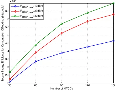
The SEE with respect to the maximum transmission power
PMTCD,max of each MTCD is demonstrated in Fig.7. Due to
the MTCDs are energy-critical devices, we set PMTCD,max as
10 dBm, 23 dBm and 30 dBm in order not to exceed that of H2H users. With the number of MTCDs is fixed, the SEE increases when the maximum transmission power of MTCDs increases, which illustrate that the system secrecy computation offloading rate grows faster than the total power consumption in our proposed algorithm. Although the larger transmission power will enhance the secrecy performance, it also aggravates the co-channel interference. Thus, the increased SEE between
Pm,max= 23dBm andPm,max= 10dBm is larger than that
betweenPm,max= 23dBm andPm,max= 30dBm.
30 60 90 120 150
2 2.5 3 3.5 4 4.5 5 5.5 6 6.5
x 109
Number of MTCDs
Secure Energy Efficiency for Computation Offloading (bits/Joule)
PMTCD,max=10dBm
PMTCD,max=23dBm
PMTCD,max=30dBm
Fig. 7. Computation Offloading SEE vs. maximum transmission power of MTCDs
0 3 6 9 12 15
0 0.2 0.4 0.6 0.8 1 1.2 1.4 1.6 1.8
2x 10
10
Staic Circuit Power Pc (dBm)
Secure Energy Efficiency for Computation Offloading (bits/Joule)
[image:12.612.72.271.257.413.2]M=60,PMTCD,max=15dBm M=60,PMTCD,max=23dBm M=120,PMTCD,max=15dBm M=120,PMTCD,max=23dBm
Fig. 8. Computation Offloading SEE vs. static circuit power of MTCDs
The performance of SEE versus the static circuit power PC of each MTCD is shown in Fig.8. The static circuit power of MTCDs varies from 0dBm to 15dBm. With the number of MTCDs and maximum transmission power fixed, the SEE decreases with the static circuit power increasing. In addition, with the increase of static circuit power, the influence of
MTCDs’ number and maximum transmission power on SEE is getting smaller and smaller, and static circuit power becomes the main factor affecting SEE. Thus, the design of MTCDs with low cost and low energy consumption is urgent.
The performance of SEE versus the total number of com-putation resource blocks in MEC server is evaluated in Fig.9. The number of CRBNCvaries from 1 to 29. With the number
of MTCDs fixed, there exists a critical value of the number of CRB. Particulary, the critical value of CRB in x-axis is the number of CRB that can meet the computation offloading requirements of MTCDs. The SEE increases when the number of CRB is smaller than the critical value, and it will keep constant if the number of CRB beyond the critical value. In addition, the critical value of requiring CRB increases with the total number of MTCDs increasing. The results imply that the CRB assigning to each MEC server should be according to the total number of served MTCDs.
0 5 10 15 20 25 30 1
2 3 4 5 6 7x 10
9
Computing Resource Block
Secure Energy Efficiency for Computation Offloading (bits/Joule)
[image:12.612.339.533.276.435.2]M=30 M=60 M=90 M=120 M=150
Fig. 9. Computation Offloading SEE vs. number of CRB
2 3 4 5 6 7 8 9 10
2 2.5 3 3.5 4 4.5 5 5.5x 10
9
Workload (Giga cycles)
Secure Energy Efficiency for Computation Offloading (bits/Joule)
M=60,Nc=10 M=60,Nc=20 M=120,Nc=10 M=120,Nc=20
Fig. 10. Computation Offloading SEE vs. workload of MTCDs
[image:12.612.72.272.478.638.2] [image:12.612.332.533.489.649.2]which lead to the system SEE decreasing. Nevertheless, the SEE can be improved by allocating more computation resource to the MEC server, which need to be execute large high concurrent computing workload.
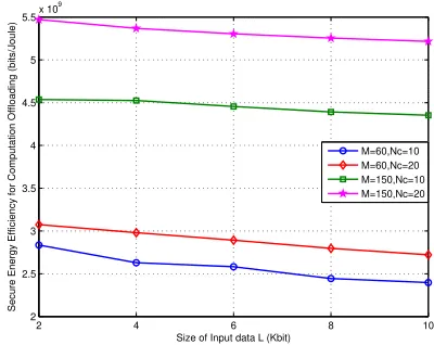
The performance of SEE versus the input data size L of each MTCD is evaluated in Fig.11. The input data size of each MTCD ranges from 2 Kbits to 10 Kbits. To fulfill the con-straint of maximum delay, the minimum secure computation offloading rate increases with the increasing of input data size, which lead to more transmission power to be needed. Thus, SEE decreases with the increasing of input data size L with given the number of MTCDs and total computing resources. Furthermore, it can be seen from Fig.11 that the influence of input data size on secrecy energy efficiency is smaller than that of MTCDs’ number and total computing resources. As the number of MTCDs increases, the total computing resources has an increasing influence on SEE.
2 4 6 8 10
2 2.5 3 3.5 4 4.5 5 5.5x 10
9
Size of Input data L (Kbit)
Secure Energy Efficiency for Computation Offloading (bits/Joule)
[image:13.612.71.271.277.436.2]M=60,Nc=10 M=60,Nc=20 M=150,Nc=10 M=150,Nc=20
Fig. 11. Computation Offloading SEE vs. input data size of MTCDs
50 150 250 350 450 550 650 750 850 950 2.5
3 3.5 4 4.5 5 5.5 6 6.5x 10
9
Delay (ms)
Secure Energy Efficiency for Computation Offloading (bits/Joule)
[image:13.612.72.268.492.650.2]M=60,Nc=10 M=60,Nc=20 M=120,Nc=10 M=120,Nc=20
Fig. 12. Computation Offloading SEE vs. delay of MTCDs
The performance of SEE versus the maximum delay D of each MTCD is evaluated in Fig.12. The maximum delay of each MTCD varies from 50 ms to 1s. With the number of MTCDs and total computation resource fixed, there exists a critical value of the maximum delay, which represents the
minimum SR that all MTCDs can reach to, i.e., DL. The minimum SR decreases with the number of MTCDs increas-ing with total computincreas-ing resources given, because limited communication resource also have influence on SR. When maximum delay is smaller than the critical value, the SEE increases with the increasing of maximum delay, while it keeps stable when maximum delay exceeds the critical value and maximum delay is no longer the main factor to constrain the SEE. In addition, when the total computation resource increasing and the number of MTCDs fixed, more computation resource will be allocated to MTCDs and the execution time will decreases, which will prolong the computation offloading time and increase the SR and SEE, thus the minimum SR decreases with the increasing of total computation resource.
VIII. CONCLUSION
With the supporting for IoT in 5G scenarios, the R-MECS was proposed to assist the NOMA based mMTC networks for IoT secure computation offloading. By sharing computation and communication resource among MTCDs, R-MECS can support many MTCDs computation tasks execution at the same time and meet the MTCDS’ various delay requirements. Specifically, based on the defined SEE, the joint computation and communication resource allocation algorithm was formu-lated to guarantee the procedure of IoT computation offloading securely and energy efficient. A MTCD-to-Subchannel match-ing algorithm was proposed to maximize the SEE in solvmatch-ing subchannel allocation problem. Furthermore, a Dinkelbach-based SEE optimization algorithm was proposed by exploiting SCA and DC programming, and the closed-form expressions of power allocation for MTCDs’ on each subchannel were ob-tained. Given the communication resource allocation schemes, the computation resource allocation problem was solved by the Knapsack algorithm. Finally, the effectiveness of the proposed algorithms and the influence of computation-communication parameters on SEE has been evaluated via simulations.
APPENDIXA PROOF OFTHEOREM1
Proof: Here, we investigate the relationship between
secrecy energy efficiency and secure offloading transmission time, where m-th MTCD with Lm,n bits computation task
need to be securely offloading to MEC through subchanneln. The secrecy computing offloading rate is
SRm,n= (rm,n,d−rm,n,e)+
= "
Wlog2 1 +pm,n
Hd
m,n
2
1 +pm,n
He
m,n
2
!#+
(25)
where Hm,nd 2
= |h
d
m,n|
2
Im,n,d and
Hm,ne
2
= |h
e
m,n|
2
Im,n,e . When
Hm,nd
2
≥
Hm,ne
2
, SRm,n = Wlog2
1+pm,n|Hm,nd |
2
1+pm,n|Hm,ne |
2
. Furthermore,
Lm,n
tT m
Then, the transmission power is
pm,n=
2SRm,nW −1
Hd m,n 2
−He m,n
2
2SRm,nW
(27)
Based on (26) and (27), the secrecy energy efficiency can be expressed as
SEEm,n=
SRm,n
pm,n
=
Lm,n
Hm,nd
2
− Hm,ne
2
2SRm,nW
tT m 2 Lm,n
tTm W −1
(28) we can obtain from (28) as following
SEEm,n tTm
≥0, SEE0m,n tTm
≥0, SEE00m,n tTm
≤0.
(29) It is easy to see SEEm,n is monotonically increasing and
concave in transmission time tT
m, and SEEm,n can be
in-creased by increasing transmission time and correspondingly decreasing power.
APPENDIXB PROOF OFTHEOREM2
Proof: According to (11), we have
Ψ∗= USC(P
∗
M,q∗B)
UT P (P∗M,q∗B)
= max
{pm,n,qn}
USC(PM,qB)
UT P(PM,qB)
(30)
whereP∗
M andq∗B are the optimal power allocation strategies
with respect to optimal SEEΨ∗. Therefore, we have
Ψ*=USC(P ∗
M,q∗B)
UT P(P∗M,q∗B)
≥ USC(PM,qB) UT P(PM,qB)
(31)
and
USC(PM,qB)−Ψ*UT P(PM,qB)≤0
USC(P∗M,q∗B)−Ψ
*U
T P(P∗M,q∗B) = 0
(32)
We can obtain that max
{p∗
m,n,q∗n}
{USC(PM,qB) −
Ψ∗UT P(PM,qB)} = 0. Thus, the sufficient condition
of Therorem 2 has been proved.
Then, the necessary condition should be proved. If
{P∗M,q∗B} is the optimal power allocation policy, we have
USC(P∗M,q∗B) − Ψ*UT P(P∗M,q∗B) = 0. Then, for any
feasible {PM,qB}, we can obtain
USC(PM,qB)−Ψ*UT P(PM,qB)
≤USC(P∗M,q
∗
B)−Ψ
*U
T P (P∗M,q
∗
B) = 0
(33) Hence,
USC(P∗M,q∗B)
UT P (P∗M,q∗B)
=Ψ*USC(PM,qB) UT P(PM,qB)
≤Ψ* (34)
Therefore, the optimal power allocation strategies
{P∗M,q∗B} of the transformed objective function is also the optimal ones of the original objective function.
APPENDIXC
PROOF OF THE CONCAVITYL(θ,A,qB)INqB
Proof: WhenA=P*M,L(θ,A,qB) =USC(A,qB)−
ΨUT P(A,qB) +P
M
m=1θm(SRm−Rm,min), then we have
L(θ,A,qB) =W
XN
n=1
XMn
m=1(θm+ 1) [f1−f2−f3+f4]
−ΨXN
n=1
XMn
m=1 1
ςpm,n+pm,C
(35) where
f1= log2
σ2+XM
i=mpi,n
hdi,n
2 +ρqn
gnR
2
f2= log2
σ2+XM
i=m+1pi,n hdi,n
2 +ρqn
gnR
2
f3=log2
σ2+XM
i0=mpi0,n hei0,n
2
+qn|gne|
2
f4=log2
σ2+XM
i0=m+1pi0,n hei0,n
2
+qn|gne|
2
Furthermorethe second derivative of f1, f2, f3, f4 with re-spect toqn are
∂2f 1
∂(qn)
2 =−
ρgR
n
22
σ2+PM
i=mpi,n
hd i,n 2
+ρqn|gnR|
22
∂2f2
∂(qn)
2 =−
ρgnR
22
σ2+PM
i=m+1pi,n
hd i,n 2
+ρqn|gnR|
22
∂2f3
∂(qn)
2 =−
|ge
n|
22
σ2+PM
i0=mpi0,n h
e i0,n
2
+qn|gne|
2 2
∂2f4
∂(qn)
2 =−
|gen|
22
σ2+PM
i0=m+1pi0,n h
e i0,n
2
+qn|gen|
2
2
(36)
where ∂∂(q2n)f12 ≈ 0 and ∂2f2
∂(qn)2 ≈ 0 if ρ is small enough, for
example ρ≤10−5. Then, we have
∂2L(P
M,qB)
∂(qn)
2
=XMn
m=1
W(θm+ 1)
|ge
n|
22
σ2+PMn
i0=mpi0,n h
e i0,n
2
+qn|gne|
2 2
−XMn
m=1
W(θm+ 1)
|gne|
22
σ2+PM
i0=m+1pi0,n h
e i0,n
2
+qn|gne|
2
2
≤0
(37)