CHARACTERIZATION OF X-BAND
MICROWAVE COMPONENTS USING
VECTOR NETWORK ANALYZER
E5071C
U.N
.SUBHADRA DEVI
1 , Assistant professor,Dept of Electronics and Communication Engineering, M.V.G.R College of Engg, Chintalavalasa Vizianagaram, 535005, Andhra Pradesh, India
Dr. M.SATYANARAYANA2,
Associate professor,
Dept of Electronics and Communication Engineering, M.V.G.R College of Engg, Chintalavalasa Vizianagaram, 535005, Andhra Pradesh, India
Abstract:
Microwave and RF testing has gained importance with increased number of microwave applications in diversified fields like defense, domestic and space applications. The characteristics of the microwave devices are found by proper examination of S-parameters, which relates power levels at different ports by using s-parameter values, auxillary s-parameters like insertion, isolation, coupling, VSWR ,reflection coefficient etc., can be obtained. Network Analyzer is a sophisticated testing device which is used to characterize active and passive components, such as amplifiers, mixers, duplexers, filters, couplers, and attenuators. These components are used in systems as common and low-cost as pagers, or in systems as complex and expensive as communications or radar systems. Components can have one port (input or output) or many ports. The ability to measure the input characteristics of each port, as well as the transfer characteristics from one port to another, gives designers the knowledge to configure a component as part of a larger system.
In this paper we find the different auxiliary parameters for different X-band microwave components like directional coupler, attenuator, isolator and circulator. These components are tested by using vector network analyzer and gives different parameters like magnitude, phase, and group delay over certain frequency range in a single moment. In this work with dynamic frequency range of 300kHZ to 14GHZ is used to test the micro wave X-band devices and the results obtained like VSWR, S-parameters, coupling factor, insertion and the isolation are very accurate.
1. Introduction:
Microwave technology is the back bone of ever increasing array of products for personal, commercial,military
and aircraft applications. The essential measurements conducted on microwave communication systems are
• RF Power out of transmitter
• The insertion loss
• Isolation loss
• Return loss
• Noise figure
• Gain
• Receiver sensitivity
X -band microwave components are very important for measurements don in laboratories, research and development side. We have different types of microwave components among them some of the important components mostly used are directional coupler, circulator, isolator , attenuator.These components are mainly used in microwave bench setups.
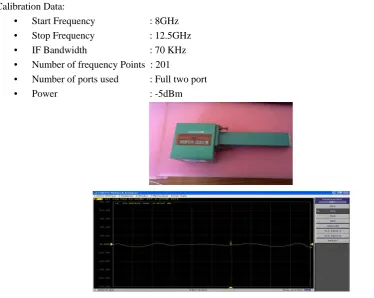
2. Some of the details of components: 2.1. Isolator
Range (GHz)
VSWR (dB) Insertion
loss(dB)
Isolation (dB)
XI-621 8.6-10.0 1.2 0.5 20
Fig 1.Isolator
2.1.1. Insertion loss:
Insertion loss is the measure of signal power which has lost when power entered in 1 and received at
port-2.It is calculated from the S21 .For an Isolator we desired to have a possible minimum of insertion loss in the
desired direction of propagation, which means the Isolator should not provide any loss in that direction. It is the extra loss produced by the introduction of the DUT between the 2 reference planes of the measurement.
Insertion loss (IL) = -20log|S21|dB (1)
2.1.2. Isolation:
Isolation is the measure of signal power which has lost when power entered in port-2 and received at port-1.This is called Isolation because the Isolator has to provide great attenuation to the signal from port-2 to port-1, which means isolating the two ports. For an Isolator we desired to have a possible maximum of isolation.
Isolation = -20log|S12|dB (2) Calibration Data:
• Start Frequency : 8GHz
• Stop Frequency : 12.5GHz
• IF Bandwidth : 70 KHz
• Number of frequency Points : 201
• Number of ports used : Full two port
• Power : -5dBm
Fig 4:S12 log Magnitude data of Isolator XI-621
Results(As observed on E5071C):
• Max insertion loss : 2.92dB at 8.6525GHz
• Minimum Insertion loss : -0.22dB at 9.6875GHz
• Minimum Isolation : 9.708dB at 9.035GHz
• Maximum Isolation : 23.176dB at 10.GHz
2.2. Circulator
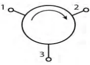
A Microwave Circulator is a passive non reciprocal three or four port ferro magnetic device , in
which microwave or radio frequency power entering any port is transmitted to the next port in rotation (only).Circulator is defined as a device with ports arranged such that the energy in a port is coupled to the adjacent port in clockwise direction but not coupled to the other ports.
The circulator shown below is a three port circulator. According to the type of physical shape, they are classified as T-shaped circulators and Y-shaped circulators, but the performance would be the same. Circulators are used
in many forms like duplexer and Isolators by using it in different configurations.
Fig 5:Symbolic representation of Three port Circulator
The Important Parameters of Circulator
2.2.1. Insertion loss:
Insertion loss is the ratio of power detected at the output port to the power supplied by source to the input port, measured with all other ports terminated in a matched load.
Insertion loss (dB) = -20log|Sji| (3)
Where power entered at ith port and received at jth port
2.2.2. Isolation:
Isolation is the ratio of power applied to the output to that measured at the input i.e, in the direction opposite of measuring insertion.
Isolation (dB) = -20log|Sij| (4)
Where power entered at jth port and received at ith port
2.2.3. Input VSWR:
It is the VSWR measured at any particular port with all other ports matched.
Reflection Coefficient |Ѓ| = VSWR-1/VSWR+1 =|Sii| (5)
Where power entered at ith port and received at ith port
2.2.4 . S-Matrix of 3-port Circulator
Manufacturer Specifications of XC-621:
33 32 31
23 22 21
13 12 11
S S S
S S S
The values are taken at 9.125GHz for comparison with the values obtained at same frequency on Microwave bench setup.
Port 2-1 Insertion loss : 1.08dB
Port 3-2 Insertion loss : 4.459dB
Port 1-3 Insertion loss : 2.03dB
Port 1-2 Isolation : 16.04dB Port 2-3 Isolation : 18.12dB Port 3-1 Isolation : 20.74dB Port-1 VSWR : 1.66 Port-2 VSWR : 1.33 Port-3 VSWR : 1.33 S-Matrix:
S-Matrix can be calculated by converting the log magnitude of auxiliary parameters into linear format.
Fig 6.: Measurement setup for testing 3- port Circulator XC-621
2.3.Waveguide attenuators
Attenuators are used to attenuate the microwave power and commonly used for measuring power gain or loss in dBs, for providing isolation between instruments, for providing the signal generators with a means of calibrating their outputs accurately so that precise measurement could be made.
Attenuators may be of the fixedor thevariable type
2.3.1. Fixed attenuator :
Fixed Attenuator consists of a dielectric slab consisting of glass slab coated with Aquadog or carbon film which
provides attenuation. The waveguide consists of lossy dielectric or vane.
Fig 7:Fixed Attenuator
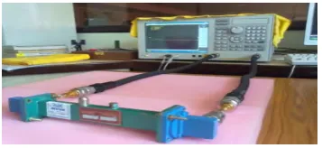
2.3.2. Varaible attenuator :
Variable Attenuators provide attenuation in continuous or stepwise variable attenuation. The variable attenuator tested on E5071C is a movable lossy vane type variable attenuator which is designed to obtain the low VSWR characteristics over entire frequency range band.
Fig 8:Variable Attenuator
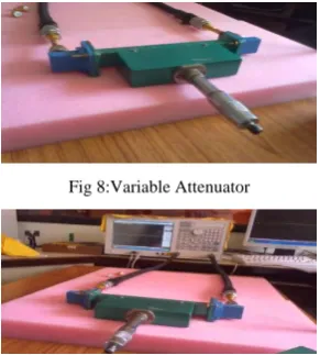
Fig 9: Variable Attenuator(XA-520) connected to E5071C
Calibration Data:
Start Frequency : 8GHz Stop Frequency : 12.5GHz IF Bandwidth : 70 KHz Number of frequency Points : 201
Number of ports used : Full two port Power : -5dBm
Parameters of Interest : S21, VSWR
Fig 10: S21 Log Magnitude of Fixed Attenuator
Results of Fixed Attenuator (as observed on E5071C):
• Minimum Attenuation : 8.04dB at 8.54GHz
• Maximum Attenuation : 12.54GHz at 12.5GHz
• Max Group Delay : 872ps at 9.035GHz
Results of Fixed Attenuator (continuation):
• Min Group Delay : 218ps at 12.5GHz
• Minimum VSWR from port1-2 : 1.62 at 12.5GHz
• Maximum VSWR from port 1-2 : 2.33 at 8.54GHz
Results of Variable Attenuator (as observed on E5071C):
• Max Attenuation (At position 0) : 33.1dB at 12.5GHz
• Minimum Attenuation (At position 20) : 0.01 dB at 11.7GHz VSWR at position 0: 1.04 at 12.5GHz
2.4. Directional Couplers
A directional coupler is a four-port microwave junction .The ideal directional coupler has the property that a wave incident in port1 couples power in to ports 2 and 3 but not in to port4. Similarly power in port 4 couples in to port2 and 3 but not in to port1. Thus port1 and 4 are uncoupled. For waves incident in port2 and 3,the power is coupled in to ports 1and 4 only ,so that port2 and 3 are also uncoupled.
In additional ,all four ports are matched. That is, if three ports are terminated in matched loads, the fourth port
appears terminated in a matched load, and an incident wave in this port suffers no reflection.
Fig 12: Schematic diagram of Directional coupler XK-610
Parameters Evaluated for Directional Coupler
• Coupling ( C ) = -20log|S31|dB
• Isolation( I ) = -20log|S32|dB
• Directivity( D ) = -20log|S43| = I-C dB
• Insertion loss = -20log|S21|
Manufacturer Specifications of XK-610:
XK-610 is a Multi Hole directional coupler (MHD) which has 4 ports with port 4 matched.
0.8 0.85 0.9 0.95 1 1.05 1.1 1.15 1.2 x 10¹⁰ -50
-45 -40 -35 -30 -25 -20 -15 -10 -5 0
Frequency in GHz
A
tt
enua
ti
o
n i
n
d
B
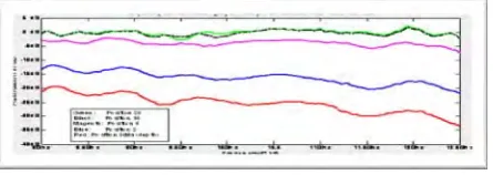
Coupling,Isolation,Directivity and Insertion vs Frequency of XK-610 directional coupler
Coupling in dB Isolation in dB Insertion in dB Directivity in dB
Model FREQ.RANGE
(GHz)
COUPLING (dB)
DIRECTIVITY (MIN.)
VSWR (MAIN)
VSWR (AUXILARY LINE)
0.8 0.85 0.9 0.95 1 1.05 1.1 1.15 1.2 x 10¹⁰ 1
1.2 1.4 1.6 1.8 2 2.2 2.4 2.6 2.8 3
Frequency in GHz
VS
W
R
VSWR of port 1, 2 , 3 vs Frequency of XK-610 MHD
VSWR of port 1 with port 2,3,4 matched VSWR of port 2 with port 1,3,4 matched VSWR of port 3 with port 1,2,4 matched
Results at particular frequency of 9.125GHz
Main Line VSWR of MHD Coupler:1.2
Auxiliary Line VSWR of MHD Coupler:1.6
Coupling: 2.85dB
Insertion:3.08dB
Isolation :51.0dB
Directivity: 48.15dB
Fig 13:Measurement Setup for Directional coupler characteristics
3. Conclusion
For fixed attenuator, it is found that attenuation is constant over entire range in between 8 to 12.5 dB. For variable attenuator (XA-520) the attenuation is a function of vane depth and attenuation tends to increase slightly as the frequency increases from 8 to 12.5GHz.Isloator XI-621 gives minimum attenuation of 9.3dB as compared to 20dB of specified minimum isolation. Insertion loss is found to be satisfactory over entire region near to 0.5dB.Circulator, XC-621 gives 16.04dB Isolation as compared to minimum of 20dB isolation and all port VSWRs are slightly greater than specified VSWR of 1.2.Multi Hole Directional Coupler (MHD) XK-610 has given satisfactory results with minimum directivity of 30dB, but coupling is around 5dB against the specified value of 10dB.VSWRs of port 1,3 is found to be good but port-2 is found to matched imperfectly, This
may be due to the fact that it is impossible to construct a perfectly matched lossless reciprocal 3-port junction.
4. References:
[1] R.E.Collin., “Chapter-6, Passive Microwave Devices, pp.259, Foundations of Microwave Engineering, Mcgraw-Hill” [2] M. Kulkarni., “Microwave and RadarEngineering III edition-2007,Umesh Publications”
[3] Constantine A. Balanis, “Chapter -14,Microstrip Antennas,pp.722 Antenna theory Analysis and Design, second edition, wiley india pvt. Ltd”
[4] Garg, R., Bhartia, P., Bahl, I, Ittipiboon, “A.,Chapter-3, Full-wave Analysis of Microstrip Antennas, pp.157., Microstrip antenna design handbook, Artechhouse,2001”
[5] G.S.N.Raju., “antennas and wave propagation”.
[6] Agilent 10 hints for making better network analyzer measurements application note 1291-1b.
Authors: