COMPARISON OF VECTOR CONTROL
OF INDUCTION MOTOR DRIVE USING
CONVENTIONAL METHOD AND LOOK
–UP TABLES WITH 6- AND
24-SECTORS
M. Siva Satyanarayana, D. Subba Rayudu, T. Brahmananda Reddy and V. Sowmya Sree [email protected], [email protected]
Abstract: The control and estimation of induction motor drives constitute a vast subject and these IM drives have been the work horses in the industries for variable speed applications from fractional horse power to multi Mega-watt power. Nowadays, vector control and direct torque control (DTC) are popular for high performance drives. Even though these methods give better performance, the vector control method needs reference frame transformations and direct torque control gives large steady state ripples. To overcome these problems in the above methods mentioned, this paper presents an advanced vector control method for voltage-source inverter fed induction motors using sophisticated look-up tables. The proposed method combines features of both indirect vector control and DTC. This method uses a predetermined look-up table instead of a much more time consuming pulse width modulation (PWM) procedure in conventional vector control for generating inverter gate signals. This approach gives faster torque response like in vector control methods and it also reduces ripples as in DTC method. To validate the proposed method numerical simulations have been carried out and compared with the existing algorithms. The simulation results confirm the effectiveness of the proposed method.
Key Words— Induction Motor Drive, Look-up table, Vector Control
I. Introduction
High performance induction motor drives require decoupled torque and flux control. This control is commonly provided through vector control [1]. Almost 38 years ago, in 1971 F. Blaschke presented a paper on vector control for induction motor. Although vector control schemes are capable of controlling the torque and flux of the induction motor independently, they require reference frame transformation, which increases the complexity of the system. With the advent of vector control scheme, the technique was completely developed and several papers have been published on vector control [3-6].
In 1985, Takahashi introduced direct torque control (DTC) scheme [7]. In contrast to vector control, DTC method requires the knowledge of stator resistance only; thereby decreasing the associated sensitivity to parameters variation and the elimination of speed information .DTC as compared to FOC is also advantageous in other aspects like absence of co-ordinate transformation and PWM modulator. DTC is also very simple in its implementation because it needs only two hysteresis comparators and a lookup table for both flux and torque control. A detailed comparison between vector control and DTC has given in [8]. Though, DTC gives fast transient response, it gives large ripple in steady state.
Hence to overcome the drawbacks of vector control and DTC, this paper presents a new vector control scheme, which combines the principles of both vector control and DTC. For the current controllers, several look-up tables have given in [9]. This paper also presents, a sophisticated look-up table based vector control algorithm. The proposed method does not require reference frame transformations and give good steady state and transient responses.
II. Mathematical Modeling of Induction Motor
The voltage expressions of a three-phase induction motor in stator reference frame are given as in (1)
dt
d
i
R
v
s
s s
s (1)dt
d
j
i
R
The dynamic equations of the induction motor can be represented by using flux linkages as variables, which involves the reduction of a number of variables in the dynamic equations. The stator and rotor flux linkages in the stator reference frame are defined as in (2).
r m s s
s
L
i
L
i
(3)r r s m
r
L
i
L
i
(4)The electromagnetic torque and electromechanical expressions of the induction motor are given by
dr qs qr ds
r m
e
i
i
L
L
P
T
2
2
3
(5) Anddt
d
J
P
T
dt
d
J
T
T
e
L
m
L
2
r (6)III. Vector Control of Induction Motor
The induction motor’s dynamic model equations are non-linear and multi-variable. Also, an additional non-linearity is seen in the machine model due to variation of machine parameters with saturation temperature and skin effect. There are also coupling effects between input and output variables i.e., both torque and flux are functions of voltage and frequency. In the vector control algorithm, the machine torque and rotor flux linkage are controlled through stator current vector control. The stator current vector is divided into a torque producing component (
i
*qs) and flux producing component (i
ds* ) in a rotating frame of reference. The flux component*
ds
i
is along the machine flux linkage vector and the torque componenti
*qs is perpendicular to the flux component. This represents the decoupling effect between torque and flux. The electromagnetic torque expression for an induction motor is given by
dr qs qr ds
r m s r r m
e
i
i
L
L
P
i
j
L
L
P
T
2
2
3
Re
2
2
3
* (7)For decoupling control, the q-axis flux component must be made equal to zero. Then the torque expression can be modified as given in (8).
dr qs
r m e
i
L
L
P
T
2
2
3
(8)Hence, the total rotor flux equal to
r
dr and given as in (9).ds m dr r
L
i
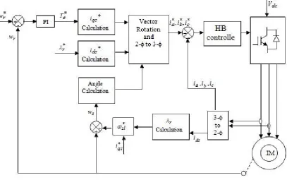
(9)Fig. 1 Block diagram of indirect vector controlled induction motor drive
The d-q axes currents then transformed from rotating to stationary and then converted from two-phase to three-phase currents. Then, the reference three-phase currents are compared with the actual three-phase stator currents in the hysteresis band type current controller, from which the pulses can be generated and given to the voltage source inverter.
IV. Proposed Vector Control Algorithm for Induction Motor
The electromagnetic torque expression for an induction motor, which is given in (7), can be represented as
sin
2
2
3
s r r m
e
i
L
L
P
T
(10)where is the angle between stator current and rotor flux linkage vectors as shown in Fig. 2.
Fig. 2 Representation of stator current vector and rotor flux linkage space vectors
From (10), it can be observed that the torque dynamics depends on the variation of . Hence, fast torque control can be achieved by rapidly changing ‘’ in the required direction. This is the basic objective of “proposed vector control”. During a short transient, the rotor flux remains almost unchanged, thus rapid changes
r
s
i
d
q
qs
ji
ds
of electromagnetic torque can be produced by rotating the d and q components of stator current vector in the required direction. By ignoring the stator resistance drop, the stator voltage expression can be represented as
dt
d
v
s
s (11)From (3) and (4), the stator flux linkage space vector can be represented as given in (12).
s r m r r m s s s
i
L
L
L
L
i
L
2
(12)Then the stator voltage expression can be represented as given in (13).
dt
i
d
L
L
dt
d
L
L
dt
i
d
L
dt
d
v
s r m r r m s s s s 2
(13)As the rotor time constant is high, the rotor flux linkage space vector will move slowly. Hence, for short time durations, the rotor flux linkage vector is assumed as constant. This simplifies the voltage expression as follows.
dt
i
d
L
dt
i
d
L
L
L
dt
d
v
s s sr m s s s
2 (14)For a short time interval of
t
, the stator current expression can be represented as given in (15).t
v
L
i
ss
s
1
(15)
Thus, the stator current space vector moves by
i
s in the direction of the stator voltage space vector at a speed proportional to magnitude of voltage space vector (i.e. dc link voltage). By selecting the appropriate stator voltage vector step-by-step, it is then possible to change the stator current in the required direction. Decoupled control of the torque and stator flux is achieved by acting on the radial (flux component currenti
ds) and tangential components (torque component currenti
qs) of the stator current vector in the locus. These two components are directly proportional to the components of the stator voltage vector in the same directions. By assuming a slow motion of the rotor flux linkage space vector, if a forward active voltage vector is applied then it causes rapid movement ofi
s and torque increases with ‘’. On the other hand, when a zero voltage vector is used, thei
s becomes stationary and the electromagnetic torque will decrease, since
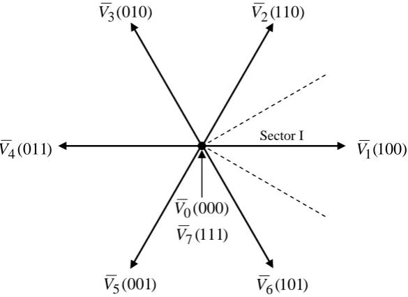
r continues to move forward and the angle ‘’ decreases. If the duration of zero voltage space vector is sufficiently long, then the rotor flux linkage space vector exceeds the stator current vector, the angle ‘’ will change its sign and the torque will also change its direction. Thus, it is possible to change the speed of stator current vector by changing the ratio between the zero and non-zero voltage vectors.Considering the three-phase, two-level, six pulse voltage source inverter (VSI), there are six non-zero active voltage space vectors and two zero voltage space vectors as shown in Fig.3. The six active voltage space vectors can be represented as
1
,
2
,...,
6
3
1
exp
3
2
V
j
k
k
V
k dc
(16)Fig. 3 Inverter voltage space vectors with 6-sector division Table 1. Optimum voltage Switching vector look up table with 6-sectors
N 1 2 3 4 5 6
Sd = 1
Sq = 1 110 010 011 001 101 100
Sq = 0 111 000 111 000 111 000
Sq = -1 101 100 110 010 011 001
Sd = 0
Sq = 1 010 011 001 101 100 110
Sq = 0 000 111 000 111 000 111
Sq = -1 001 101 100 110 010 011
)
111
(
7
V
)
100
(
1
V
)
101
(
6
V
)
001
(
5
V
)
011
(
4
V
)
010
(
3
V
V
2(
110
)
)
000
(
0
V
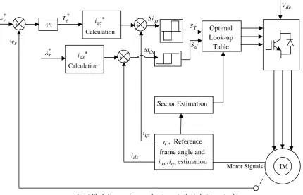
The proposed vector controlled induction motor drive block diagram s shown in fig.4
Fig. 4 Block diagram of proposed vector controlled induction motor drive
As in conventional vector control, the proposed vector control algorithm generates d- and q- axes commands. Then as in DTC, the proposed algorithm uses hysteresis current controllers and switching table. Thus, the proposed algorithm eliminates time consuming PWM procedure. The generated
d
andq
axis current commands are compared with their actual current values obtained from the measured phase currents. The current errors are used to produce d and q flags as inputs to the switching table. A third input to the table determines the sector through which the current vector is passing. It is produced by having the d and q axis currents and the rotor position. The switching table provides the proper voltage vectors by deciding on the status of the inverter switches. In field oriented control, the current decoupling network is a feed forward (indirect) method to produce flux orientation. In proposed control system, Current decoupling means to determine the reference current space phasori
ds*,
i
*qs,
based on reference rotor flux
*r and torque Te*. Based on the outputs of hysteresis controllers and position of the stator current vector, the optimum switching table will be constructed. This gives the optimum selection of the switching voltage space vectors for all the possible stator current vector positions. As in DTC, the stator flux linkage and torque errors are restricted within their respective hysteresis bands, which are2
i
ds and2
i
qs respectively.For the current control strategy it is enough to analyze only signs of voltage vector components
V
sd
andsq
V
.For the control
Sd
i
theV
sd
component is1
d
K
AndV
sd
0
1
d
K
AndV
sd
0
IM qs i Calculation + - * r w r w PI * e T dc V + - ds i Calculation * r + -Motor Signals , Reference
frame angle and
qs ds i
i , estimation
0
d
K
AndV
sd
0
(17)
and for the control
Sy
i
theV
sq
component is1
q
K
AndV
sq
0
1
q
K
AndV
sq
0
0
q
K
AndV
sq
0
(18)
Where
d
K
andq
K
are digitized output signals of the comparators. To find relation between signs of componentsV
sd
,
V
sq
and inverter output voltage vector, it is necessary to detect the position of the field coordinatesd
q
. The digitized variablesK
d,
K
q and the rotor flux positionN
-(sectors) create a digital word, which by accessing the set of switching pulses
c
S
b
S
a
S
,
,
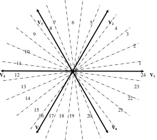
presented in Table 1. In contrast to the approach presented by Rodriquez and Kastner, the complex plane is divided not into six but into 24 sectors. This provides very convenient operation with three-level hysteresis comparators and more precise selection of the output vectors. Each sector is delimited as shown in Fig. 5. The selection table is created according to the following principles: in each sector the vector is chosen whoseV
sd
andV
sq
components have the same sign as the comparator outputsq
K
d
K
,
respectively; if the above condition is satisfied for two vectors the one lying closer to the symmetry axis is chosen; the zero vector is a applied when both comparators are in zero state.V3 7 6 5 V2
8 4
9 3
2 10
11 1
V4 12 24 V1
13 23
14 22
15 21
16 17 18 19 20
V5 V6
Table 2. Optimum voltage switching vector lookup table
Kd Kq
1 2 3 4 5 6 7 8 9 10 11 12 13 14 15 16 17 18 19 20 21 22 23 24
1 1 V2 V2 V2 V3 V3 V3 V3 V4 V4 V4 V4 V5 V5 V5 V5 V6 V6 V6 V6 V1 V1 V1 V1 V2 1 0 V1 V1 V2 V2 V2 V2 V3 V3 V3 V3 V4 V4 V4 V4 V5 V5 V5 V5 V6 V6 V6 V6 V1 V1 1 -1 V6 V1 V1 V1 V1 V2 V2 V2 V2 V3 V3 V3 V3 V4 V4 V4 V4 V5 V5 V5 V5 V6 V6 V6 0 1 V3 V3 V3 V3 V4 V4 V4 V4 V5 V5 V5 V5 V6 V6 V6 V6 V1 V1 V1 V1 V2 V2 V2 V2 0 0 V0 V0 V0 V0 V0 V0 V0 V0 V0 V0 V0 V0 V0 V0 V0 V0 V0 V0 V0 V0 V0 V0 V0 V0 0 -1 V6 V6 V6 V6 V1 V1 V1 V1 V2 V2 V2 V2 V3 V3 V3 V3 V4 V4 V4 V4 V5 V5 V5 V5 -1 1 V3 V4 V4 V4 V4 V5 V5 V5 V5 V6 V6 V6 V6 V1 V1 V1 V1 V1 V1 V2 V2 V2 V2 V3 -1 0 V4 V4 V5 V5 V5 V5 V6 V6 V6 V6 V1 V1 V1 V1 V2 V2 V2 V2 V3 V3 V3 V3 V4 V4 -1 -1 V5 V5 V5 V6 V6 V6 V6 V1 V1 V1 V1 V2 V2 V2 V2 V3 V3 V3 V3 V4 V4 V4 V4 V5
V. Simulation Results
To verify the proposed algorithm, a numerical simulation has been carried out using MATLAB-Simulink. The induction motor parameters are: Rs= 4.1Ω, Rr= 2.5 Ω, Ls= 0.545 H, Lr= 0.542 H, Lm= 0.51 H,
number of poles = 4 and J = 0.04 Kg-m2. The results of conventional vector control and proposed vector control algorithms are presented and compared. The simulation studies have been carried for various conditions such as starting, steady state, load change and speed reversal with a PI type speed controller. The results of conventional vector control algorithm are given in Fig. 6 – Fig. 10 and the results of proposed algorithm for 6-sectors are given in Fig.11–Fig.15andfor24-sectorsaregiveninFig.16–Fig.
Fig.6 starting transients in conventional vector control algorithm
Fig.8 transients during load change in conventional vector control algorithm
Fig.9 transients during speed reversal (speed is changed from +1000 rpm to -1000 rpm)
Fig.11 Motor speed, stator current and torque during the starting period.
Fig.12 Motor speed, stator current and torque during the steady state period.
Fig14 during the speed reversal positive to negative.
Fig.16 Motor speed, stator current and torque during the starting period
Fig.18 during the load variation.
Fig.19Motor speed, stator current and torque during the speed reversal positive to negative
Fig.20 Motor speed, stator current and torque during the speed reversal negative to positive
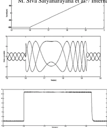
1. From the results shown, it can be observed that for all 3 cases of conventional control and using look up tables with 6 sectors and 24 sectors. The starting period is considered from time t = 0 – 0.3 sec. Initially speed increases linearly till 0.17 sec., and goes to steady state after overcoming the rotor inertia. The stator current is initially high and decreases slowly. The torque linearly increases and rapidly reaches to maximum point at 0.02 sec till 0.17 sec., and then decreases to zero and remains same. But the starting transients are reduced in stator currents using look up tables compared with that of conventional control.
2. The steady state period is considered from time t = 0.3 to 0.5 seconds and in all the 3 cases, the motor speed, stator current and electro magnetic torque are maintained constant. The main advantage of using look up table with 6 sector and 24 sectors is that the torque ripples are reduced which are found to be high in conventional control.
3. The case of load variation is considered from t = 0.5 – 0.9 sec. The step load is applied at t = 0.6 sec., and removed at 0.8 seconds. During this period, the speed decreases, the stator current and torque increases as they are directly prop. To each other but speed is inversely proportional to load. After 0.8 sec., all parameters came to original state. In conventional control, the stator current decreases and came to original state but using look up table with both 6 & 24 sectors the stator current directly comes to original state with any change. 4. In case of speed reversal from positive to negative during t = 0.9 – 1.5 seconds. The speed varies from positive to negative during t = 1 – 1.33 sec., the stator current increases but torque decreases. But the value of current Ia during the period is higher in case of proposed algorithm with 6 sectors and 24 sectors and the current
Ib remains in steady state for more time than in conventional vector control.
5. The case of speed reversal from negative to positive at t = 1.5 – 2 sec. During t=1.6 – 1.93 sec., the speed varies from negative to positive, the sector current and torque increases. The current Ia. is small in case of
proposed algorithm with 6 sectors and 24 sectors and the current Ic remains in steady state for less time than in
conventional vector control.
VI. Simulation Results
References: [1] Peter Vas, “Sensorless vector and direct torque control” Oxford university press, New York, 1998.
[2] F. Blaschke “The principle of field orientation as applied to the new transvector closed loop control system for rotating-field machines," Siemens Review, 1972, pp 217-220.
[3] W. Leonhard, “30 years of space vectors, 20 years of field orientation, 10 years of digital signal processing with controlled AC-drives, a review (Part1)". EPE Journal, No. 1, July 1991, pages 13-20.
[4] W. Leonhard, “30 years of space vectors, 20 years of field orientation, 10 years of digital signal processing with controlled AC-drives, a review (Part 2)". EPE Journal, No. 2, Oct, 1991, pages 89-102.
[5] E. D. Mitronikas, A. N. Safacas, and E. C. Tatakis, “A new stator resistance tuning method for stator-flux-oriented vector-controlled induction motor drive,” IEEE Trans. Ind. Electron., vol. 48, no. 6, pp.1148–1157, Dec. 2001.
[6] J. A. Santisteban, and R. M. Stephan, “Vector control methods for induction machines: an overview,” IEEE Trans. On Education, vol. 44, no. 2, pp. 170-175, May 2001.
[7] Isao Takahashi and Toshihiko Noguchi, “A new quick-response and high-efficiency control strategy of an induction motor,” IEEE Trans. Ind. Applicat., vol. IA-22, no.5, Sep/Oct 1986, pp. 820-827.
[8] Domenico Casadei, Francesco Profumo, Giovanni Serra, and Angelo Tani, “FOC and DTC: Two Viable Schemes for Induction Motors Torque Control” IEEE Trans. Power Electron., vol. 17, no.5, Sep, 2002, pp. 779-787.